
Understanding Pascal’s Law in Pressure Instruments: A Deep Dive for Instrumentation Professionals and Students
In the intricate world of industrial automation and process control, the precise measurement of pressure stands as a cornerstone of safety, efficiency, and quality. From massive hydraulic presses shaping metal with immense force to sophisticated sensors ensuring the stability of a chemical reactor, the principles governing pressure are fundamental. At the heart of many of these applications lies a simple yet profound concept discovered in the 17th century: Pascal’s Law.
For both seasoned instrumentation professionals and aspiring students, a thorough grasp of Pascal’s Law is not just academic; it’s a foundational piece of knowledge that demystifies the workings of a vast array of pressure instruments. This comprehensive guide will delve into the depths of Pascal’s Law, explore its practical applications in various pressure measurement devices, and provide clear block diagrams to illuminate these concepts.
What is Pascal’s Law? A Principle of Pressure Transmission
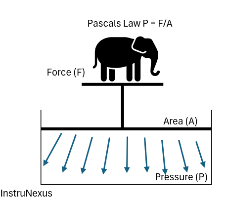
At its core, Pascal’s Law, formulated by the brilliant French mathematician and physicist Blaise Pascal, states that:
A pressure change at any point in a confined incompressible fluid is transmitted throughout the fluid such that the same change occurs everywhere.
In simpler terms, if you apply pressure to a fluid that is enclosed in a container, that pressure is distributed equally to all parts of the fluid and the walls of the container. The fluid must be incompressible, meaning its volume doesn’t change significantly under pressure, a characteristic common to most liquids.
The mathematical representation of pressure is given by the formula:
Where:
- P is the pressure
- F is the force applied
- A is the area over which the force is applied
Pascal’s Law extends this by implying that the pressure at any two points in a continuous, enclosed fluid at rest is the same. This principle is the magic behind how a small force can be multiplied into a much larger force, a concept that has revolutionized engineering.
Think of squeezing a tube of toothpaste. When you apply pressure with your fingers (a small force on a small area), the pressure is transmitted throughout the paste, forcing it out of the nozzle. The pressure you apply is felt everywhere within the tube.
Here is a basic illustration of Pascal’s Law:
The Quintessential Example: The Hydraulic Press
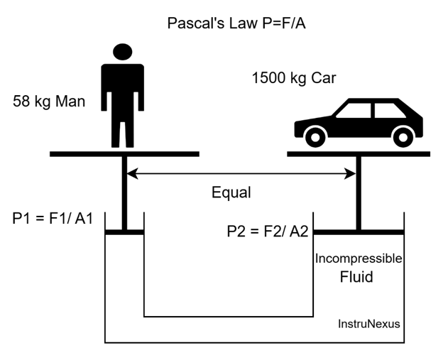
Perhaps the most classic and easily understood application of Pascal’s Law is the hydraulic press. This device elegantly demonstrates the force-multiplying effect of this principle.
A hydraulic press consists of two pistons of different cross-sectional areas, A1 and A2 (where A2 is significantly larger than A1), in a U-shaped tube filled with an incompressible fluid, typically oil.
When a small force, F1, is applied to the smaller piston (A1), it creates a pressure in the fluid (P1 = F1/A1). According to Pascal’s Law, this pressure is transmitted undiminished throughout the fluid and acts on the larger piston. Therefore, the pressure on the larger piston, P2, is equal to P1.
So, we have:
This can be rearranged to find the output force, F2:
F_2 = (F_1 /A_1)* A_2
Since A2 is much larger than A1, the output force F2 will be proportionally much larger than the input force F1. This is the principle that allows a person to lift a car with a hydraulic jack or for industrial presses to shape metal with seemingly little effort.
Block Diagram of a Hydraulic Press:
Industrial Applications of Hydraulic Presses:
- Manufacturing: Stamping, bending, and forming metal sheets into car bodies, appliance parts, and more.
- Forging: Shaping large blocks of metal into strong components for aerospace and heavy machinery.
- Waste Compaction: Crushing and baling recyclable materials.
- Assembly: Press-fitting bearings and other components with high precision.
Manometers: The Visual Forefathers of Pressure Measurement
Long before the advent of digital sensors, engineers and scientists relied on manometers to measure pressure. These simple yet effective devices are a direct and visual representation of Pascal’s Law at work. A manometer measures pressure by balancing the pressure of the fluid in question against the pressure exerted by a column of a known liquid.
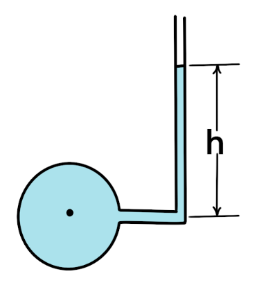
1. Simple Manometer (Piezometer)
The simplest form of a manometer is a piezometer, which is a tube attached to a point where the pressure of a liquid is to be measured. The liquid from the source rises in the tube to a height that balances the pressure. The height of the liquid column directly indicates the gauge pressure.
Working Principle: The pressure at the base of the liquid column inside the piezometer is equal to the pressure of the fluid at the point of attachment, as per Pascal’s Law.
Block Diagram of a Simple Manometer:
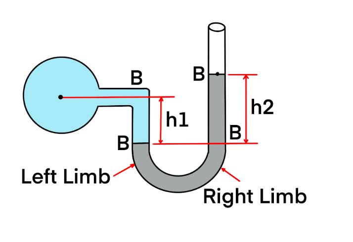
2. U-Tube Manometer
The U-tube manometer is a more versatile instrument. It consists of a U-shaped glass tube partially filled with a manometric fluid, such as mercury or water. One end is connected to the point where pressure is to be measured, and the other end is open to the atmosphere.
Working Principle: If the pressure of the source is higher than atmospheric pressure, it pushes the manometric fluid down in the connected limb and up in the open limb. The difference in the height of the fluid levels in the two limbs is a measure of the gauge pressure. This is a direct application of Pascal’s principle where the applied pressure is transmitted through the manometric fluid.
Block Diagram of a U-Tube Manometer:
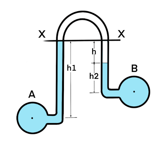
3. Differential Manometer
A differential manometer is used to measure the pressure difference between two points in a pipe or between two different pipes. Both ends of the U-tube are connected to the pressure sources.
Working Principle: The difference in the fluid levels in the manometer is proportional to the difference in pressure between the two points. Pascal’s Law ensures that the pressures from both sources are accurately transmitted to the manometric fluid.
Block Diagram of a Differential Manometer:
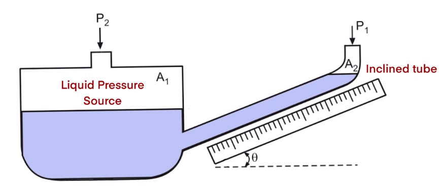
4. Inclined Manometer
For measuring very small pressures with high accuracy, an inclined manometer is used. The reading limb is inclined at an angle to the horizontal.
Working Principle: A small change in the vertical height of the manometric fluid results in a much larger movement along the inclined tube. This “stretches” the scale, allowing for more precise readings of low pressures. Pascal’s Law still governs the transmission of pressure to the fluid.
Block Diagram of an Inclined Manometer:
Industrial Applications of Manometers:
- HVAC Systems: Measuring air pressure in ducts to ensure proper ventilation.
- Filter Monitoring: Monitoring the pressure drop across filters to determine when they need cleaning or replacement.
- Leak Detection: Identifying pressure losses in gas lines.
- Laboratory Experiments: Used in a wide range of scientific experiments requiring precise low-pressure measurements.
Pressure Transducers: Translating Pressure into Electrical Signals
In modern instrumentation, it’s often necessary to convert pressure into an electrical signal that can be read by a controller, data logger, or display. This is the role of a pressure transducer. While the internal mechanisms of transducers are more complex than manometers, the initial stage of sensing pressure often relies on the principles of Pascal’s Law. The applied pressure is transmitted to a sensing element, causing a physical change that is then converted into an electrical output.
1. Strain-Gauge Pressure Transducers
These are one of the most common types of pressure transducers. They use a strain gauge, which is a sensor whose resistance changes when it’s stretched or compressed.
Working Principle: The pressure to be measured is applied to a diaphragm. According to Pascal’s Law, this pressure is transmitted uniformly across the diaphragm’s surface, causing it to deflect or deform. This deformation creates a mechanical strain in the diaphragm. A strain gauge bonded to the diaphragm experiences this strain and changes its electrical resistance. This change in resistance is typically measured using a Wheatstone bridge circuit, which produces a voltage output proportional to the pressure.
Block Diagram of a Strain-Gauge Pressure Transducer:

2. Capacitive Pressure Transducers
Capacitive pressure transducers measure pressure by detecting a change in capacitance. A capacitor consists of two conductive plates separated by a dielectric material.
Working Principle: In a capacitive transducer, one of the capacitor plates is a flexible diaphragm that is exposed to the process pressure. The other plate is fixed. As the process pressure increases, Pascal’s Law dictates that the pressure is transmitted to the diaphragm, causing it to move closer to the fixed plate. This change in the distance between the plates alters the capacitance of the sensor. An electronic circuit measures this change in capacitance and converts it into an electrical signal proportional to the pressure.
Block Diagram of a Capacitive Pressure Transducer:

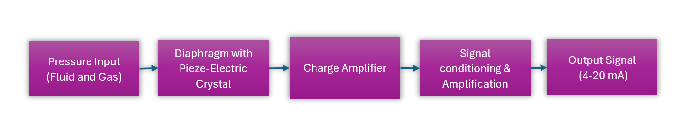
3. Piezoelectric Pressure Transducers
Piezoelectric transducers are ideal for measuring dynamic or rapidly changing pressures. They utilize the piezoelectric effect, which is the ability of certain materials (like quartz) to generate an electrical charge in response to applied mechanical stress.
Working Principle: The process pressure is transmitted via a diaphragm to a piezoelectric crystal. As the pressure fluctuates, it exerts a varying force on the crystal. This mechanical stress causes the crystal to generate a proportional electrical charge. An electrode collects this charge, and a charge amplifier converts it into a high-impedance voltage signal. Because the charge dissipates over time, these sensors are not suitable for measuring static pressures but excel at measuring dynamic pressures in applications like engine combustion analysis and explosion testing.
Block Diagram of a Piezoelectric Pressure Transducer:
Industrial Applications of Pressure Transducers:
- Oil and Gas: Monitoring wellhead and pipeline pressures.
- Chemical Processing: Ensuring safe and efficient operation of reactors and distillation columns.
- Aerospace: Measuring hydraulic and fuel pressures in aircraft.
- Automotive: Monitoring oil pressure, fuel pressure, and tire pressure.
- Food and Beverage: Ensuring consistent pressures in filling and carbonation processes.
Conclusion: The Enduring Legacy of Pascal’s Law
From the simple, elegant mechanics of the U-tube manometer to the sophisticated inner workings of a modern piezoelectric transducer, the influence of Pascal’s Law is undeniable. This fundamental principle of fluid mechanics, though centuries old, remains a cornerstone of pressure measurement technology.
For instrumentation professionals and students, understanding how this law governs the transmission of pressure in a confined fluid is key to comprehending the operation, selection, and troubleshooting of a vast range of pressure instruments. It is the invisible force that connects the pressure in a pipe to the reading on a gauge, the force on a piston to the lifting of a heavy load, and the strain on a diaphragm to the electrical signal that controls a critical process. As technology continues to evolve, the fundamental principles like Pascal’s Law will always remain the bedrock upon which innovation in instrumentation is built.