
In the world of industrial automation and process control, the precise measurement of pressure is paramount. From ensuring the safety of a chemical reactor to optimizing the efficiency of a hydraulic system, accurate pressure data is the lifeblood of countless operations. At the heart of this critical function lies a ubiquitous and indispensable device: the pressure transmitter. This comprehensive overview will delve into the working principles of various pressure transmitters, explore their diverse applications, and provide instrumentation professionals and students with a thorough understanding of this essential technology.
What is a Pressure Transmitter?
A pressure transmitter is a sophisticated sensor that measures the pressure of a fluid (liquid or gas) and converts it into a standardized electrical signal. This signal, typically a 4-20 mA current loop, a 0-10 V DC voltage, or a digital signal (like HART or Modbus), can then be transmitted over a distance to a control system, such as a Programmable Logic Controller (PLC), a Distributed Control System (DCS), or a simple display.
Think of a pressure transmitter as a translator. It “reads” the physical language of pressure and “speaks” the electrical language that control systems understand. This translation enables operators and automated systems to monitor, control, and record pressure levels with exceptional accuracy and reliability.
The Inner Workings: A General Block Diagram
Before we dissect the different types of pressure transmitters, let’s look at a generalized block diagram that illustrates their core functionality:


- Sensing Element: This is the part of the transmitter that comes into direct or indirect contact with the process medium. It’s designed to physically deform or change in some way in response to the applied pressure. The most common sensing element is a diaphragm.
- Transduction Element: This is the core of the pressure transmitter. It converts the physical change from the sensing element into a detectable electrical signal. The type of transduction element defines the type of pressure transmitter.
- Signal Conditioning & Amplification: The initial electrical signal from the transduction element is often very small and may be non-linear. The signal conditioning circuitry linearizes, amplifies, and compensates for temperature variations to produce a clean and accurate signal.
- Output Stage: This stage converts the conditioned signal into the standardized output format (e.g., 4-20 mA, 0-10V, or a digital protocol).
Now, let’s explore the most common types of pressure transmitters based on their transduction principle.
Types of Pressure Transmitters and Their Working Principles
The ingenuity of pressure measurement lies in the various physical principles harnessed to convert pressure into an electrical signal. Here are the most prevalent types:
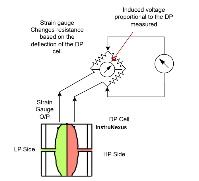
1. Strain Gauge Pressure Transmitters
Strain gauge pressure transmitters are the workhorses of the industry, known for their robustness, accuracy, and wide pressure range. They operate on the principle of the piezoresistive effect, where the electrical resistance of a material changes when it is subjected to mechanical strain.
Working Principle:
- Pressure Application: The process pressure is applied to a diaphragm, causing it to deflect.
- Strain Induction: This deflection is mechanically transferred to a strain gauge, which is bonded to the diaphragm or a connected sensing element. The strain gauge is essentially a metallic foil pattern on a flexible backing.
- Resistance Change: As the strain gauge is stretched or compressed, its electrical resistance changes.
- Wheatstone Bridge: The strain gauge is typically part of a Wheatstone bridge circuit. The change in resistance unbalances the bridge, producing a small output voltage that is directly proportional to the applied pressure.
- Signal Conversion: This voltage is then conditioned and converted into a standard output signal.
Block Diagram of a Strain Gauge Pressure Transmitter:
2. Capacitive Pressure Transmitters
Capacitive pressure transmitters are renowned for their high accuracy, excellent long-term stability, and ability to measure very low pressures. They work by measuring the change in capacitance caused by the deflection of a diaphragm.
Working Principle:
- Capacitor Plates: The core of a capacitive pressure sensor consists of two parallel plates that form a capacitor. One plate is a fixed electrode, while the other is a flexible diaphragm exposed to the process pressure.
- Diaphragm Deflection: When pressure is applied, the diaphragm deflects, changing the distance between the two plates.
- Capacitance Variation: The capacitance of a parallel plate capacitor is inversely proportional to the distance between the plates. Therefore, as the diaphragm moves, the capacitance changes.
- Oscillator Circuit: This change in capacitance is measured by an oscillator circuit. The frequency of the oscillator changes in proportion to the change in capacitance.
- Signal Conversion: The change in frequency is then converted into a DC voltage or current signal that corresponds to the applied pressure.
Block Diagram of a Capacitive Pressure Transmitter:

Piezoelectric pressure transmitters are ideal for measuring dynamic or rapidly changing pressures. They utilize the piezoelectric effect, where certain crystalline materials generate an electrical charge when subjected to mechanical stress.
Working Principle:
- Piezoelectric Crystal: A piezoelectric crystal (like quartz) is placed in contact with a diaphragm that is exposed to the process pressure.
- Charge Generation: When the pressure changes, it exerts a force on the crystal, causing it to deform. This deformation generates an electrical charge across the crystal faces.
- Dynamic Measurement: The magnitude of the generated charge is proportional to the applied force (and thus the pressure). It’s important to note that piezoelectric sensors are not suitable for static pressure measurement, as the charge will eventually leak away. They excel at measuring pressure fluctuations, pulsations, and explosions.
- Charge Amplification: The generated charge is very small and requires a charge amplifier to convert it into a usable voltage signal.
Block Diagram of a Piezoelectric Pressure Transmitter:
[Dynamic Process Pressure] -> [Force on Piezoelectric Crystal] -> [Charge Generation] -> [Charge Amplifier] -> [Signal Conditioning] -> [Output Voltage Signal]
4. Resonant Pressure Transmitters
Resonant pressure transmitters are known for their exceptional accuracy and long-term stability. They operate on the principle that the resonant frequency of a vibrating element changes when it is subjected to stress.
Working Principle:
- Vibrating Element: A precisely machined vibrating element, often a silicon resonator, is placed under tension and is connected to a diaphragm.
- Stress Induction: The process pressure deflects the diaphragm, which in turn changes the tension and stress on the vibrating element.
- Frequency Change: The resonant frequency of the vibrating element is a function of its tension. As the pressure changes, the tension on the element changes, causing its resonant frequency to shift.
- Frequency Detection: An electronic circuit causes the element to resonate and precisely measures its frequency.
- Signal Conversion: The change in resonant frequency is then converted into a highly accurate pressure reading.
Block Diagram of a Resonant Pressure Transmitter:
[Process Pressure] -> [Diaphragm Deflection] -> [Change in Tension of Vibrating Element] -> [Change in Resonant Frequency] -> [Frequency Detection Circuit] -> [Signal Conditioning] -> [Output Signal (Digital/Analog)]
A World of Applications: Where Pressure Transmitters Shine
The applications for pressure transmitters are vast and span nearly every industrial sector. Here are some key examples:
Oil and Gas Industry:
- Upstream: Monitoring wellhead pressure, and injection pressure for enhanced oil recovery.
- Midstream: Ensuring pipeline integrity by monitoring pressure and detecting leaks.
- Downstream: Controlling pressure in distillation columns, reactors, and storage tanks in refineries.
Pharmaceutical and Food & Beverage Industries:
- Hygienic Applications: Utilizing transmitters with sanitary fittings to monitor pressure in pipelines and vessels during food and beverage production.
- Sterilization: Ensuring proper pressure levels in autoclaves and steam-in-place (SIP) systems.
- Filtration and Separation: Monitoring differential pressure across filters to determine when they need to be cleaned or replaced.
Manufacturing and Automation:
- Hydraulic Systems: Monitoring and controlling pressure in hydraulic presses, lifts, and other machinery.
- Pneumatic Systems: Ensuring the correct operating pressure for pneumatic tools and actuators.
- Level Measurement: In a sealed tank, the pressure at the bottom can be used to calculate the level of the liquid inside (hydrostatic level measurement).
Aerospace and Automotive:
- Testing: Measuring aerodynamic pressures in wind tunnels and engine test cells.
- Control Systems: Monitoring hydraulic and fuel pressures in aircraft and vehicles.
Water and Wastewater Management:
- Pumping Stations: Monitoring pump discharge pressure to ensure efficient water distribution.
- Level Measurement: Measuring the level in water towers and reservoirs.
- Flow Measurement: When used with a primary flow element like an orifice plate, a differential pressure transmitter can accurately measure the flow rate of a fluid.
Choosing the Right Pressure Transmitter: Key Considerations
Selecting the appropriate pressure transmitter for a specific application is crucial for ensuring accuracy, reliability, and safety. Here are some factors to consider:
- Accuracy: How precise does the measurement need to be?
- Pressure Range: What are the minimum and maximum pressures the transmitter will be exposed to?
- Media Compatibility: Is the wetted material of the transmitter (the parts in contact with the process fluid) resistant to corrosion or erosion from the fluid?
- Operating Temperature and Environment: Can the transmitter withstand the temperature and environmental conditions of the installation location (e.g., hazardous areas, high vibrations)?
- Output Signal: Is a 4-20 mA, voltage, or digital output required?
- Long-Term Stability: How well will the transmitter maintain its accuracy over time?
The Future of Pressure Measurement
The world of pressure transmitters is constantly evolving. The trend is moving towards “smart” transmitters that incorporate microprocessors for enhanced diagnostics, remote configuration, and communication capabilities through protocols like HART, Foundation Fieldbus, and Profibus. The integration of wireless technology and the Internet of Things (IoT) is also revolutionizing how pressure data is collected and utilized, enabling predictive maintenance and greater operational insights.
In conclusion, the humble pressure transmitter is a cornerstone of modern industry. Its ability to accurately and reliably convert the invisible force of pressure into a tangible electrical signal empowers engineers and operators to maintain control, ensure safety, and optimize efficiency across a staggering array of applications. For any instrumentation professional or student, a deep understanding of these devices is not just beneficial—it is fundamental.