

Control valve working principle
In the world of industrial processes, there exists a silent workhorse, a device that, without much fanfare, orchestrates the precise and relentless flow of liquids and gases. This unsung hero is the control valve. From the gasoline in your car to the clean water in your tap, and from the life-saving medications you rely on to the electricity that powers your home, the humble control valve plays a pivotal role in making it all possible.
This comprehensive blog post will pull back the curtain on the world of control valves. We will embark on a journey to understand their fundamental nature, dissect their working principles, explore the vast array of types available, and marvel at their diverse applications across countless industries. So, whether you’re an engineering student, a seasoned industry professional, or simply a curious mind, prepare to gain a newfound appreciation for this critical component of our modern world. At nearly 2500 words, this article aims to be a definitive guide to understanding control valves.
What is a Control Valve? The Heart of Process Control
At its core, a control valve is a power-operated device designed to modulate the flow of a fluid (which can be a liquid, gas, or slurry) in a pipeline. Unlike a simple on/off valve, which only has two states – fully open or fully closed – a control valve can be positioned at any point between these two extremes. This ability to precisely regulate the rate of flow is what makes it an indispensable tool in any automated control system.
Imagine trying to maintain a specific temperature in a chemical reactor. A simple on/off valve could only either flood the reactor with a cooling agent or completely cut it off, leading to wild temperature swings. A control valve, on the other hand, can continuously adjust the flow of the coolant, making minute changes to keep the temperature at the desired setpoint with remarkable accuracy.
To truly appreciate the function of a control valve, we must view it as the “muscle” of a larger system known as a feedback control loop.
Block Diagram: The Feedback Control Loop

In this loop:
- The Sensor measures the current state of the process variable (e.g., temperature, pressure, flow rate, or level).
- The Controller (often a PLC or DCS) receives this measurement and compares it to the desired setpoint. If there’s a difference, the controller calculates the necessary corrective action.
- The Control Valve, acting as the final control element, receives a signal from the controller and adjusts its position to modify the fluid flow, thereby bringing the process variable back to the setpoint.
Deconstructing the Control Valve: A Look at its Core Components
A control valve is not a single entity but an assembly of several key components working in harmony. Understanding these parts is crucial to grasping its operation.
Block Diagram: Components of a Control Valve
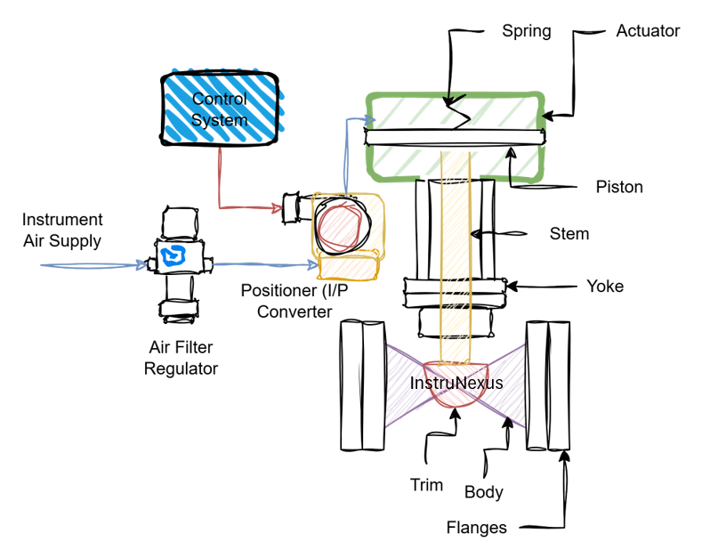
Valve Body: This is the main pressure-containing structure of the valve and is directly connected to the pipeline. It houses the internal components that come into contact with the process fluid. The body must be robust enough to withstand the pressure, temperature, and corrosive nature of the fluid.
Trim: The term “trim” refers to the internal components of the valve that are in direct contact with the flowing fluid and are responsible for the flow modulation. The primary parts of the trim are:
- Plug (or Disc): This is the movable part that obstructs the flow path. The shape and design of the plug are critical as they determine the flow characteristic of the valve (more on this later).
- Seat: This is the stationary part against which the plug rests in the closed position to provide a seal. The precision with which the plug and seat are machined determines the leakage rate of the valve.
Bonnet: The bonnet is the cover for the opening in the valve body. It supports the actuator and the packing, and it guides the stem. In some designs, particularly for high-temperature applications, the bonnet may have fins to dissipate heat and protect the actuator.
Actuator: The actuator is the “engine” of the control valve. It is the component that receives the control signal from the controller and converts it into the mechanical motion required to move the valve plug. Actuators are broadly classified into three types:
- Pneumatic Actuators: These are the most common type and use compressed air to generate motion. They are known for their reliability, high power-to-weight ratio, and fail-safe action (the ability to move to a predefined safe position upon loss of air supply).
- Electric Actuators: These use an electric motor to drive the valve stem. They are ideal for applications where compressed air is not readily available and offer precise positioning.
- Hydraulic Actuators: These utilize a high-pressure fluid (typically oil) to generate very high thrust, making them suitable for large valves and high-pressure applications.
Yoke and Packing: The yoke connects the actuator to the bonnet, while the packing is a sealing system that prevents the process fluid from leaking along the stem.
Positioner: While not always present, a positioner is a crucial accessory for many control valves. It is a device that ensures the valve plug moves to the exact position dictated by the controller, regardless of factors like friction or pressure imbalances. It acts as a local controller for the actuator, improving the accuracy and responsiveness of the valve.
The Working Principle: A Symphony of Control
Now that we understand the components, let’s bring them all together to understand how a control valve works. The process is a continuous and dynamic dance of measurement, comparison, and action.
Sensing and Signal Transmission: A sensor in the process line measures the controlled variable (e.g., the pressure in a pipeline). This measurement is converted into an electrical or digital signal and sent to the controller.
Controller’s Decision: The controller compares the measured value to the desired setpoint. For instance, if the pressure is too high, the controller will determine that the valve needs to close further to restrict the flow.
Signal to the Actuator: The controller then sends a corresponding signal to the actuator of the control valve. In the case of a pneumatic actuator, this might be a change in the air pressure (e.g., from 3 to 15 psi). For an electric actuator, it could be a change in the voltage or current (e.g., from 4 to 20 mA).
Actuator in Motion: The actuator receives this signal and translates it into mechanical movement. A pneumatic diaphragm actuator, for example, will use the change in air pressure to move a diaphragm, which in turn moves the valve stem.
Modulating the Flow: The movement of the stem repositions the valve plug relative to the seat. If the controller signaled to reduce the pressure, the plug moves closer to the seat, reducing the orifice size and restricting the flow of the fluid.
Process Correction: As the flow is restricted, the pressure in the pipeline begins to decrease.
Continuous Feedback: The sensor continuously measures the changing pressure and sends this updated information back to the controller. This closed-loop feedback mechanism allows the system to make ongoing, fine-tuned adjustments until the process variable stabilizes at the setpoint.
A World of Choices: Types of Control Valves
Control valves are not a one-size-fits-all solution. They come in a wide variety of designs, each with its own set of advantages and best-suited applications. They are primarily categorized based on the motion of the closing element: linear motion and rotary motion.
Linear Motion Control Valves
In these valves, the closing element (the plug) moves in a straight line to modulate the flow.
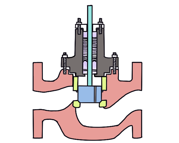
Globe Valves:
- Description: Globe valves are perhaps the most common type of linear motion control valve. They have a globular body and a movable disc (plug) that moves perpendicular to the seat. The S-shaped flow path through the valve body creates a significant pressure drop, which is beneficial for throttling applications.
- Advantages: Excellent throttling capability, good shutoff, and can be easily serviced.
- Disadvantages: High pressure drop, which means higher energy consumption.
- Variations:
- Single-Seated: Provides tight shutoff but is subject to higher forces from the process fluid.
- Double-Seated: More balanced design with lower actuator force requirements but generally has poorer shutoff characteristics.
- Three-Way: Used for mixing or diverting flows.
Gate Valves:
- Description: Gate valves use a flat, wedge-shaped, or rectangular gate that slides across the flow path. They are primarily designed for on/off service and are not ideal for throttling as the high fluid velocity during partial opening can cause significant wear.
- Advantages: Low pressure drop when fully open, tight shutoff.
- Disadvantages: Poor throttling characteristics, prone to vibration when partially open.
Diaphragm Valves:
- Description: These valves use a flexible diaphragm to control the flow. The diaphragm is pressed against a weir or a seat to restrict or stop the flow. This design isolates the valve’s working parts from the process fluid, making them ideal for corrosive or sanitary applications.
- Advantages: Excellent for handling corrosive and viscous fluids, no packing leaks.
- Disadvantages: Limited to moderate temperatures and pressures due to the diaphragm material.
Rotary Motion Control Valves
In rotary motion valves, the closing element rotates to open or close the flow path.
Ball Valves:
- Description: Ball valves feature a spherical closure element with a bore through it. A quarter-turn (90-degree) rotation of the ball either aligns the bore with the flow path (open) or moves it perpendicular to the flow path (closed).
- Block Diagram: Ball Valve (Quarter-Turn Operation)
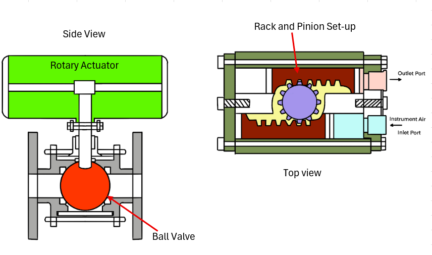
- Advantages: High flow capacity, low pressure drop, excellent shutoff, and relatively low cost.
- Variations:
- V-notch Ball Valves: These have a V-shaped notch in the ball, providing more precise flow control, making them suitable for throttling applications.
- Floating vs. Trunnion Mounted: Floating ball designs are common for smaller sizes, while trunnion-mounted designs provide better support for the ball in larger and higher-pressure applications.
Butterfly Valves:
- Description: Butterfly valves use a circular disc that rotates on a shaft to control the flow. Like ball valves, they are a quarter-turn design.
- Advantages: Lightweight, compact, low cost, and suitable for large diameter pipelines.
- Disadvantages: The disc is always in the flow path, which can cause a pressure drop even when fully open. Shutoff is not as tight as globe or ball valves.

Plug Valves:
- Description: Similar to ball valves, plug valves use a cylindrical or tapered plug with a bore. They are also a quarter-turn design.
- Advantages: Simple design, durable, and reliable in on/off applications.
- Disadvantages: Higher torque required for operation compared to ball valves.
Flow Characteristics: The Personality of a Control Valve
A crucial aspect of control valve selection is its flow characteristic. This describes the relationship between the valve’s travel (how much it’s open) and the flow rate through it. The shape of the valve plug primarily determines this characteristic. The three main inherent flow characteristics are:
Linear: In a linear characteristic valve, the flow rate is directly proportional to the valve travel. A 50% open valve will allow 50% of the maximum flow. These are often used in liquid level control and other processes where the pressure drop across the valve is expected to remain relatively constant.
Equal Percentage: For an equal percentage valve, each equal increment of valve travel produces an equal percentage change in the existing flow rate. This means that at low openings, a small change in stem position results in a small change in flow, while at larger openings, the same change in stem position results in a much larger change in flow. This characteristic is beneficial in processes where large variations in pressure drop are expected, such as in temperature and pressure control loops.
Quick Opening: A quick opening valve provides a large increase in flow for a small initial opening of the stem. These are best suited for on/off applications or for relief valves where a large flow is needed quickly.

It’s important to distinguish between the inherent flow characteristic (measured in a lab under constant pressure drop) and the installed flow characteristic (how the valve behaves in a real system where the pressure drop changes with the flow rate). A skilled engineer will select a valve with an inherent characteristic that results in a near-linear installed characteristic for the specific application, ensuring stable and predictable control.
Where the Magic Happens: Applications of Control Valves
The applications of control valves are as vast and varied as the industries they serve. Here’s a glimpse into some of their key roles:
Oil and Gas: From the wellhead to the refinery, control valves are essential for managing the flow and pressure of crude oil, natural gas, and refined products. They are used in separators, pipelines, and distillation columns.
Chemical Processing: In chemical plants, control valves are at the heart of reactor temperature and pressure control, pH control, and the precise mixing of reactants. Their ability to handle corrosive and hazardous materials is critical.
Power Generation: In power plants (both fossil fuel and nuclear), control valves are used to regulate the flow of steam to the turbines, control boiler feedwater, and manage cooling water systems. The precision and reliability of these valves are paramount for safety and efficiency.
Water and Wastewater Treatment: Control valves are used to manage the flow of water through treatment plants, control chemical dosing for purification, and regulate the pressure in distribution networks.
Pharmaceuticals: In the highly regulated pharmaceutical industry, control valves are used in bioreactors, sterilization processes, and the manufacturing of medicines, where precision and sanitary conditions are non-negotiable.
Food and Beverage: From controlling the flow of ingredients in a food processing plant to regulating the carbonation of beverages, control valves ensure product consistency and quality.
HVAC (Heating, Ventilation, and Air Conditioning): Control valves are used to regulate the flow of hot and chilled water in commercial and industrial HVAC systems to maintain comfortable indoor temperatures.
More Than Just a Valve
The control valve, though often hidden from view, is a testament to the ingenuity of modern engineering. It is a device that embodies the principles of precision, reliability, and control. Its ability to tame the powerful forces of flowing fluids is what enables industries to operate safely, efficiently, and with a level of automation that was once unimaginable.