
How to Interpret Control Valve Symbols on P&IDs (With Examples)
In the intricate world of process industries, Piping and Instrumentation Diagrams (P&IDs) serve as the definitive roadmap. These detailed drawings provide a graphical representation of the piping, equipment, and instrumentation within a processing plant. For engineers, technicians, and operators, the ability to decipher these diagrams is a fundamental skill, and at the heart of this skill lies the understanding of control valve symbols.
Control valves are the final control elements in most automated systems, modulating the flow of fluids to maintain process variables at their desired setpoints. Consequently, their accurate representation on P&IDs is crucial for safety, operation, and maintenance. This comprehensive guide will walk you through the essentials of interpreting control valve symbols on P&IDs, complete with detailed explanations and practical examples.
The Anatomy of a Control Valve Symbol
A control valve symbol on a P&ID is more than just a simple icon; it’s a composite of several smaller symbols that, together, provide a wealth of information about the valve’s type, actuation method, and failure mode. A typical control valve symbol can be broken down into three main parts:
- Valve Body Symbol: This represents the type of valve and how it interacts with the process fluid.
- Actuator Symbol: This indicates the mechanism that provides the force to operate the valve.
- Failure Mode Indicator: This specifies the position the valve will move to in the event of a power or signal loss.
Let’s delve into each of these components in detail.
Understanding Valve Body Symbols
The foundation of any control valve symbol is the representation of the valve body itself. Different valve types have distinct symbols, and recognizing these is the first step in understanding the valve’s function.
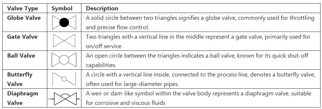
Block Diagram 1: Common Valve Body Symbols
Decoding Actuator Symbols
The actuator is the powerhouse of the control valve, converting a control signal into the physical motion required to open or close the valve. The actuator symbol sits atop the valve body symbol on a P&ID.
Here are some of the most common actuator symbols:
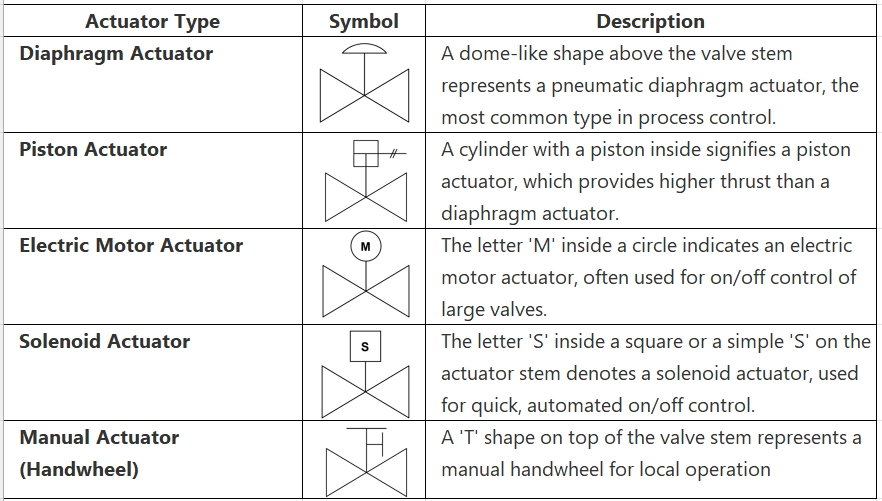
Block Diagram 2: Common Actuator Symbols
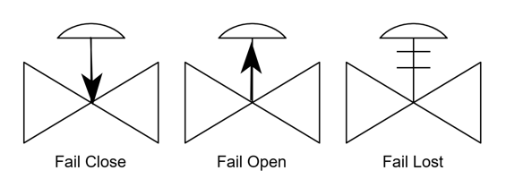
The Critical Role of Failure Mode Indication
A crucial piece of information for safety and process design is the valve’s fail-safe position. This is the position the valve will assume if the control signal or power source fails. On a P&ID, this is typically indicated by an arrow on the actuator symbol or by a set of letters.
Fail Open (FO): In the event of a failure, the valve opens. This is desired in applications where continued flow is necessary to prevent a hazardous situation, such as a cooling water system. The P&ID symbol for a fail-open valve typically has an arrow pointing away from the valve body.
Fail Close (FC): Upon failure, the valve closes. This is the most common failure mode and is used in applications where stopping the flow is the safest option, such as a fuel gas line to a burner. The P&ID symbol for a fail-close valve has an arrow pointing towards the valve body.
Fail in Last Position (FL) or Fail Indeterminate (FI): The valve remains in its last known position upon failure. This is often used with electric motor actuators where the valve position is held by gearing.
Block Diagram 3: Failure Mode Symbols
Putting It All Together: Reading the Full Control Valve Symbol
Now that we’ve covered the individual components, let’s combine them to interpret a complete control valve symbol.
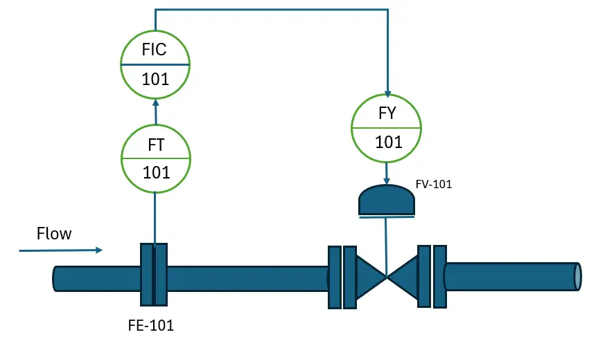
Example 1: A Simple Control Loop
Consider the following P&ID snippet:
Here’s a step-by-step interpretation:
- Instrumentation Bubble (FIC 101): The circle indicates a field-mounted instrument. The letters “FIC” stand for Flow Indicating Controller. The number “101” is the loop number, a unique identifier for this control loop.
- Control Signal: The dashed line represents an electrical signal from the controller to the valve.
- I/P Transducer (IY 101): The square with a diamond inside indicates a shared control/display system, and the “IY” tag signifies an I/P (current-to-pneumatic) transducer. This device converts the electrical control signal into a pneumatic signal to operate the valve.
- Control Valve Symbol:
- Valve Body: The solid circle between the triangles indicates a globe valve.
- Actuator: The dome shape represents a pneumatic diaphragm actuator.
- Failure Mode: The arrow pointing towards the valve body signifies that this is a fail-close (FC) valve.
- Valve Tag (FV 101): “FV” stands for Flow Valve, and “101” links it to the same control loop.
In summary, this P&ID shows a flow indicating controller (FIC 101) that sends an electrical signal to a fail-close, pneumatically actuated globe valve (FV 101) to control the flow in the pipe.
Example 2: A Temperature Control Loop with a Different Valve
Let’s look at another example:
Interpretation:
- Instrumentation Bubble (TIC 202): This is a Temperature Indicating Controller for loop 202. The solid line in the middle of the circle indicates it’s located in a primary control room.
- Control Signal: An electrical signal is sent to the valve.
- Control Valve Symbol:
- Valve Body: The symbol with the internal vertical line represents a butterfly valve.
- Actuator: The ‘M’ in the circle indicates an electric motor actuator.
- Failure Mode: The absence of a fail-safe arrow and the nature of the motor actuator suggest a fail in last position (FL). Often, for motor-operated valves, the fail-safe condition is explicitly written next to the symbol if it’s not FL.
- Valve Tag (TV 202): “TV” stands for Temperature Valve for loop 202.
In this case, the P&ID depicts a temperature indicating controller (TIC 202) in a control room that operates a motor-actuated butterfly valve (TV 202) which will remain in its last position if the power fails.
Pro Tips for P&ID Interpretation
- Always Check the Legend: Every set of P&IDs should include a legend that defines all the symbols used. While many symbols are standardized by organizations like the International Society of Automation (ISA), companies may have their own variations.
- Understand the Process Context: Knowing the purpose of the process line and the equipment involved will help you deduce the logic behind the choice of valve type and failure mode.
- Trace the Loop: Follow the signal lines to understand how the valve is being controlled. Is it a simple on/off control, or is it part of a complex modulating control loop?
- Look for Additional Information: Pay attention to any text or notes around the valve symbol, as they can provide crucial details about its size, material, or specific operational requirements.
Conclusion
Mastering the art of interpreting control valve symbols on P&IDs is an indispensable skill for anyone working in the process industries. By breaking down the symbols into their core components—the valve body, the actuator, and the failure mode indicator—you can unlock a wealth of information about the valve’s design and function. The ability to read these symbols accurately and efficiently will not only enhance your understanding of the process but also contribute to a safer and more efficient plant operation. The next time you encounter a P&ID, you’ll be well-equipped to decipher its language and understand the critical role that control valves play in the grand symphony of process control.