
What Is SIL? Safety Integrity Levels
In the intricate and often hazardous world of industrial operations, from sprawling chemical plants and offshore oil rigs to complex manufacturing facilities, ensuring safety is not just a priority; it’s a fundamental necessity. As technology advances and processes become more automated, the systems responsible for maintaining safety have grown in sophistication. Central to this landscape of modern industrial safety is the concept of the Safety Integrity Level (SIL). While the acronym is frequently mentioned among engineers and safety professionals, its true meaning and significance can often seem shrouded in technical jargon. This blog post aims to demystify SIL, providing a comprehensive, 2000-word guide to what it is, why it matters, and how it is implemented in practice, complete with illustrative block diagrams to illuminate the core concepts.
The Genesis of SIL: A Need for Quantifiable Safety
At its core, a Safety Integrity Level (SIL) is a quantitative measure of the reliability of a safety function. It represents the degree of risk reduction provided by a safety-related system. In simpler terms, SIL tells you how much you can trust a safety system to do its job when it’s called upon to prevent or mitigate a hazardous event.
The concept of SIL emerged from the growing need to move beyond purely qualitative safety assessments. Historically, safety measures were often prescriptive, based on established industry practices and incident-based learning. However, as industrial processes became more complex and the potential consequences of failures more severe, a more rigorous, performance-based approach was required. This led to the development of international standards, most notably IEC 61508 and its process industry-specific derivative, IEC 61511. These standards provide a framework for the entire lifecycle of safety systems, with SIL as a cornerstone for defining the required performance.
Understanding the Four Levels of Safety Integrity
SIL is categorized into four discrete levels, from SIL 1 to SIL 4. The higher the SIL level, the greater the risk reduction the safety function must provide, and consequently, the more stringent the requirements for its design, implementation, and maintenance.
SIL 1: Represents the lowest level of safety integrity. It is typically applied where a failure has minor consequences, perhaps leading to a small financial loss or a minor, non-disabling injury.
SIL 2: Indicates a moderate level of risk reduction. A failure at this level could result in more significant equipment damage, a more serious but non-fatal injury, or a localized environmental release.
SIL 3: Is associated with high-risk scenarios. A failure here could lead to a fatality, a major environmental incident, or significant financial losses. The majority of critical safety functions in high-hazard industries fall into the SIL 2 and SIL 3 categories.
SIL 4: Represents the highest level of safety integrity and is reserved for situations with catastrophic consequences, such as multiple fatalities or widespread, long-term environmental damage. SIL 4 applications are rare and are more commonly found in sectors like the nuclear industry and railway signaling.
The performance of a safety function is measured in terms of its Probability of Failure on Demand (PFD) for systems that operate on demand (e.g., an emergency shutdown system) or its Probability of Failure per Hour (PFH) for systems that operate continuously.
The Risk Reduction Factor (RRF) is the inverse of the PFD and provides a more intuitive understanding of the safety function’s performance. For example, a SIL 2 safety function is expected to reduce the risk of a hazardous event by a factor of between 100 and 1,000.
The Heart of the Matter: Safety Instrumented Systems (SIS)
SIL is not a property of a single component but of an entire Safety Instrumented Function (SIF), which is a safety function with a specified SIL. A SIF is implemented by a Safety Instrumented System (SIS). An SIS is an independent layer of protection designed to automatically bring a process to a safe state when predetermined conditions are violated. It is crucial to understand that an SIS operates independently of the Basic Process Control System (BPCS), which is responsible for the normal operation of the plant.
An SIS typically consists of three key elements, as illustrated in the block diagram below:
Block Diagram: Components of a Safety Instrumented System (SIS)
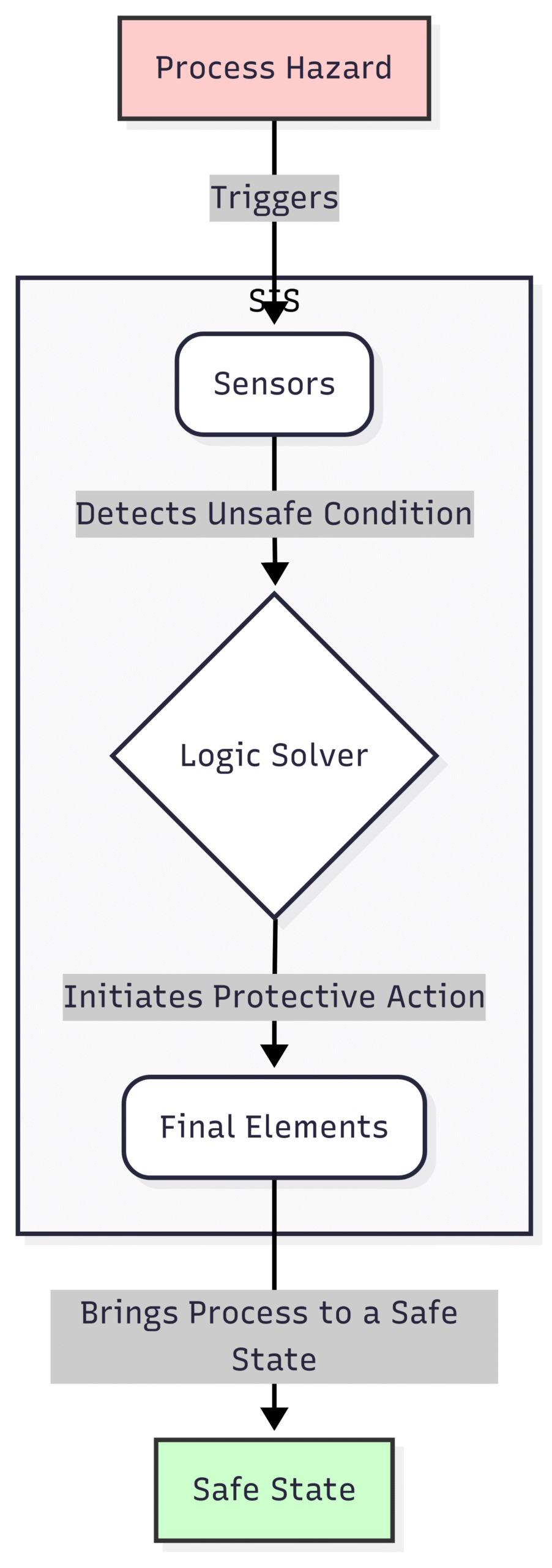
Sensors: These are the eyes of the SIS. They continuously monitor process variables such as pressure, temperature, flow, or level. Examples include pressure transmitters, temperature sensors, and gas detectors.
Logic Solver: This is the brain of the SIS. It is typically a safety-rated programmable logic controller (PLC) or a hardwired relay system. The logic solver receives signals from the sensors, executes pre-programmed safety logic, and determines whether a hazardous condition exists.
Final Elements: These are the hands of the SIS. They are the devices that physically carry out the protective action to bring the process to a safe state. Common final elements include emergency shutdown valves, relief valves, and motor trips.
The reliability of each of these components contributes to the overall SIL of the SIF. To achieve higher SIL levels, a higher degree of reliability and fault tolerance is required. This often involves the use of redundant components (e.g., multiple sensors or valves) and more rigorous testing and maintenance procedures.
How is SIL Determined? A Journey Through Risk Analysis
The determination of the required SIL for a particular safety function is a critical and systematic process. It is not a matter of guesswork but a structured analysis of the risks associated with a specific process. The overarching goal is to reduce the identified risks to a tolerable level. The process generally involves the following steps:
Hazard Identification and Risk Assessment: The first step is to systematically identify potential hazards in a process. A widely used technique for this is the Hazard and Operability Study (HAZOP). A HAZOP team, comprising engineers from various disciplines, operators, and safety specialists, brainstorms potential deviations from the intended design and operation of a process and analyzes their consequences.
Risk Evaluation: Once hazards are identified, their associated risks are evaluated. This involves considering the severity of the potential consequences (e.g., impact on people, environment, and assets) and the likelihood of the hazardous event occurring.
Risk Reduction Allocation: If the identified risk is deemed unacceptably high, layers of protection must be put in place to reduce it. These layers can include the BPCS, alarms that require operator intervention, pressure relief devices, and, crucially, the SIS. The SIL determination process quantifies the amount of risk reduction that must be provided by the SIS.
Several methods are used for SIL determination, with the Layer of Protection Analysis (LOPA) and the Risk Graph method being two of the most common.
Layer of Protection Analysis (LOPA)
LOPA is a semi-quantitative method that provides a more detailed and data-driven approach to SIL determination. It builds upon the information gathered during a HAZOP and systematically analyzes the layers of protection that are in place to prevent a specific hazardous event.
Block Diagram: Layer of Protection Analysis (LOPA) Process
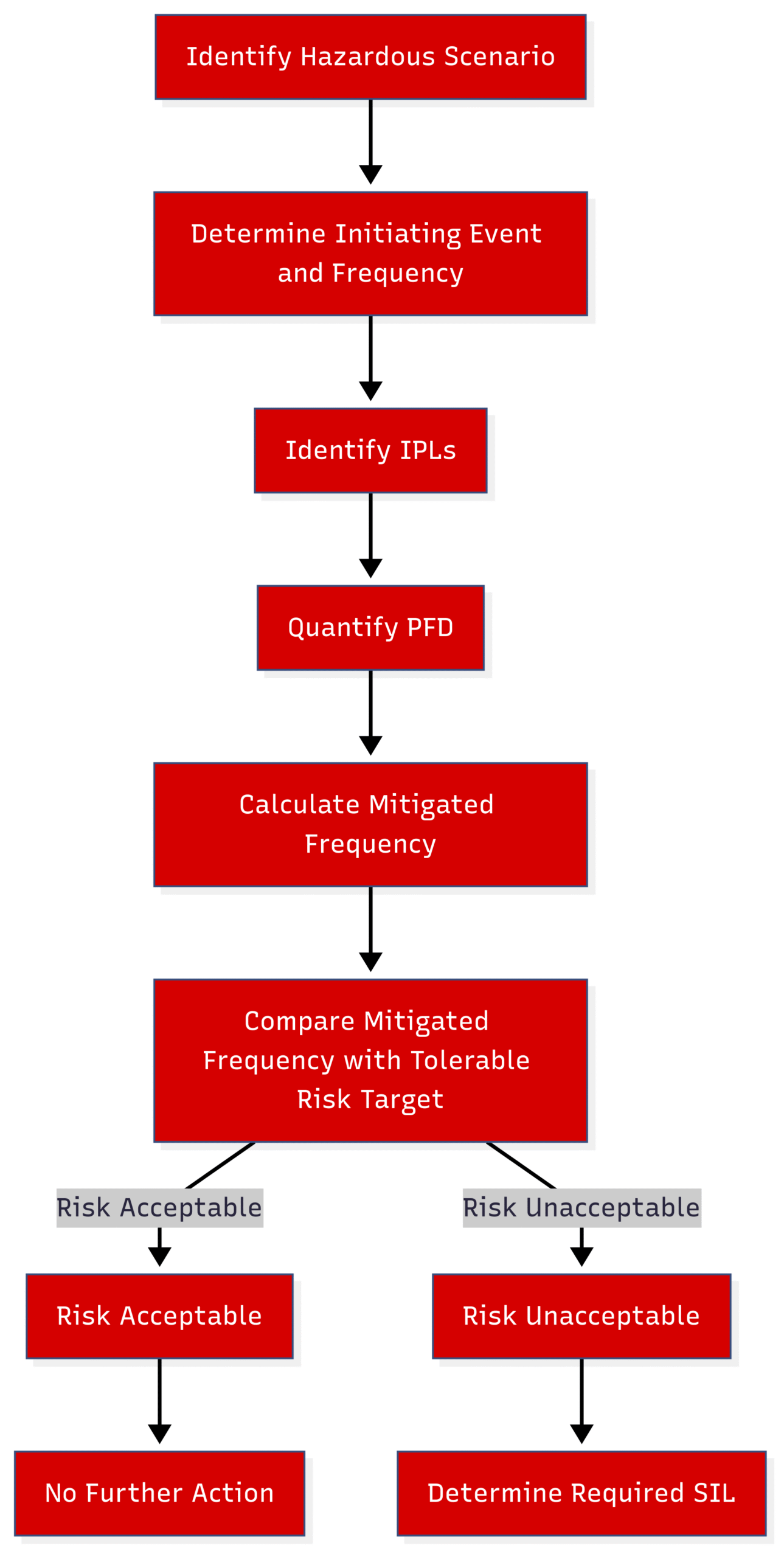
The core principle of LOPA is to determine if the existing Independent Protection Layers (IPLs) are sufficient to reduce the risk to a tolerable level. An IPL is a device, system, or action that is capable of preventing a hazardous event from proceeding to its undesired consequence and is independent of the initiating event and the other layers of protection. If the existing IPLs are not sufficient, a new SIF with a specific SIL is required to close the gap.
Risk Graph Method
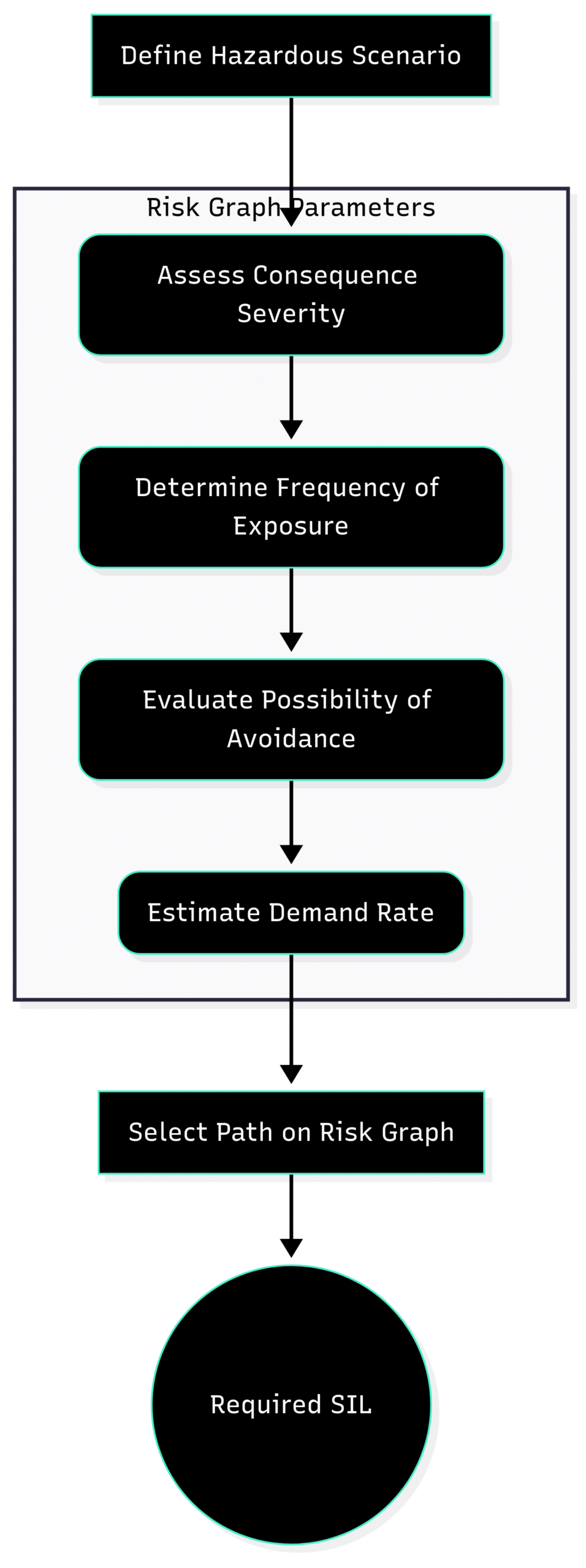
The Risk Graph method is a more qualitative approach that uses a calibrated decision-making tool to determine the required SIL. It considers several parameters to assess the risk of a hazardous scenario:
Consequence (C): The severity of the outcome if the safety function fails.
Frequency of Exposure (F): How often personnel are in the hazardous zone.
Possibility of Avoiding the Hazard (P): Whether it is possible to avoid the hazardous event once it begins.
Demand Rate (W): How often the safety function is likely to be called upon.
By selecting the appropriate categories for each of these parameters, a path is traced through the risk graph to arrive at the required SIL.
Block Diagram: Risk Graph Method for SIL Determination
While simpler to apply, the Risk Graph method is more subjective than LOPA and is often used for initial screening or for less complex systems.
The Safety Lifecycle: A Holistic Approach to Functional Safety
The determination of SIL is just one part of a much broader framework known as the Safety Lifecycle, as defined in IEC 61511. The safety lifecycle provides a structured, systematic approach to managing functional safety throughout the entire life of a plant, from initial concept to decommissioning.
Block Diagram: The IEC 61511 Safety Lifecycle
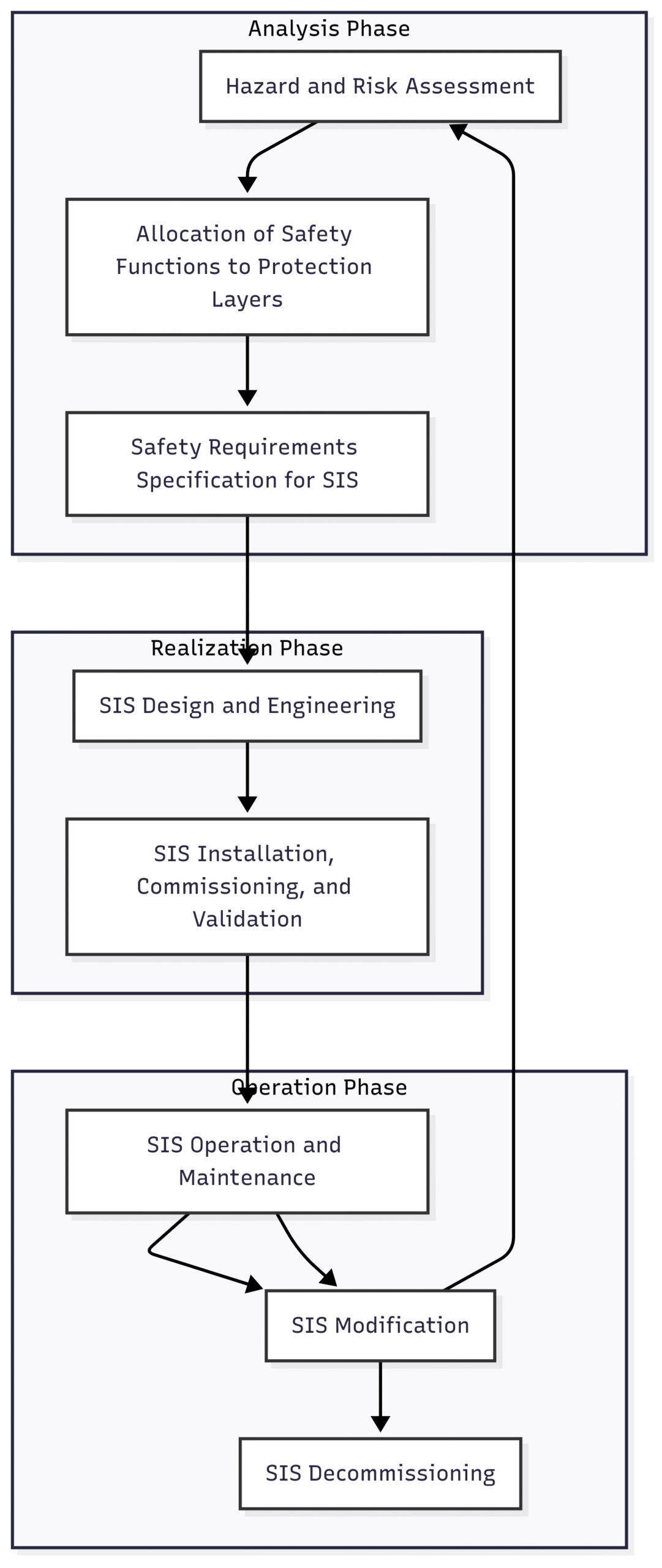
The safety lifecycle emphasizes that safety is not a one-time activity but an ongoing process of assessment, implementation, operation, and improvement. Each phase of the lifecycle has specific requirements and deliverables, all aimed at ensuring that the SIS performs its safety functions reliably and effectively.
SIL in Action: Real-World Applications
The principles of SIL are applied across a wide range of industries where safety is paramount.
Oil and Gas Industry: In offshore drilling, a SIL 3-rated Blowout Preventer (BOP) system is a critical safety barrier to prevent uncontrolled releases of oil and gas. In a refinery, a SIL 2-rated emergency shutdown system might be used to isolate a unit in case of a major leak or fire.
Chemical Processing: The manufacturing of highly reactive chemicals often involves processes with the potential for runaway reactions. A SIL 3-rated SIS would be used to monitor the temperature and pressure of a reactor and inject a “quenching” agent to stop the reaction if it exceeds safe limits.
Pharmaceutical Manufacturing: In the production of potent active pharmaceutical ingredients (APIs), SIL-rated systems are used to ensure containment and prevent operator exposure to hazardous substances.
Conclusion: SIL as a Pillar of Modern Industrial Safety
Safety Integrity Levels are far more than just a set of numbers or a bureaucratic hurdle. They represent a fundamental shift towards a performance-based, data-driven approach to industrial safety. By quantifying the required reliability of safety functions, SIL provides a clear and unambiguous target for engineers, operators, and maintenance personnel.
The journey to achieving and maintaining the required SIL is a rigorous one, demanding a deep understanding of the process hazards, a systematic approach to risk assessment, and a disciplined adherence to the principles of the safety lifecycle. However, the rewards are immeasurable. A well-designed and properly managed SIL program is a cornerstone of a robust safety culture, protecting lives, safeguarding the environment, and ensuring the long-term viability of industrial operations in an increasingly complex world. The next time you see the term “SIL,” you will know that behind it lies a comprehensive and vital framework dedicated to making our industrial world a safer place.