
Case Study: Implementing Functional Safety in a Greenfield Refinery Project
Abstract: The modern refinery is a complex symphony of high pressures, extreme temperatures, and volatile materials. Ensuring the safety of personnel, the environment, and the asset itself is paramount. This case study delves into the systematic implementation of functional safety in a new, large-scale refinery project, adhering to the stringent international standards IEC 61511 and IEC 61508. We will explore the journey from initial hazard identification to the final validation of the Safety Instrumented Systems (SIS), highlighting the challenges faced and the solutions implemented to achieve a robust and reliable safety infrastructure.
Introduction: The Imperative of Functional Safety in Refining
The oil and gas industry operates at the frontier of technological advancement and inherent risk. Refineries, the heart of downstream operations, are intricate facilities where the potential for catastrophic incidents is an ever-present concern. Functional safety is a critical discipline that focuses on the correct functioning of safety-related systems to mitigate these risks. It is not merely about adding safety devices but about a holistic, lifecycle-based approach to ensuring that automated safety functions perform as intended when called upon.
This case study follows the “Greenfield Refinery Project,” a fictional yet representative example of a modern refinery designed to process 400,000 barrels of crude oil per day. From the outset, the project stakeholders committed to embedding functional safety principles into the very fabric of the refinery’s design and operational philosophy. The primary goal was to achieve a level of safety that is “As Low As Reasonably Practicable” (ALARP), a cornerstone of modern safety regulations.
The Foundation: Adherence to International Standards
The project was governed by two key international standards:
IEC 61508: Functional Safety of Electrical/Electronic/Programmable Electronic Safety-related Systems. This is the umbrella standard for functional safety and sets out the requirements for ensuring that systems are designed, implemented, operated, and maintained to provide the required Safety Integrity Level (SIL).
IEC 61511: Functional Safety – Safety Instrumented Systems for the Process Industry Sector. This standard is a specific interpretation of IEC 61508 for the process industry, including refineries. It provides a framework for the entire lifecycle of a Safety Instrumented System (SIS).
The project adopted the safety lifecycle model prescribed by IEC 61511, a systematic and auditable approach to managing functional safety.
Block Diagram: The IEC 61511 Safety Lifecycle
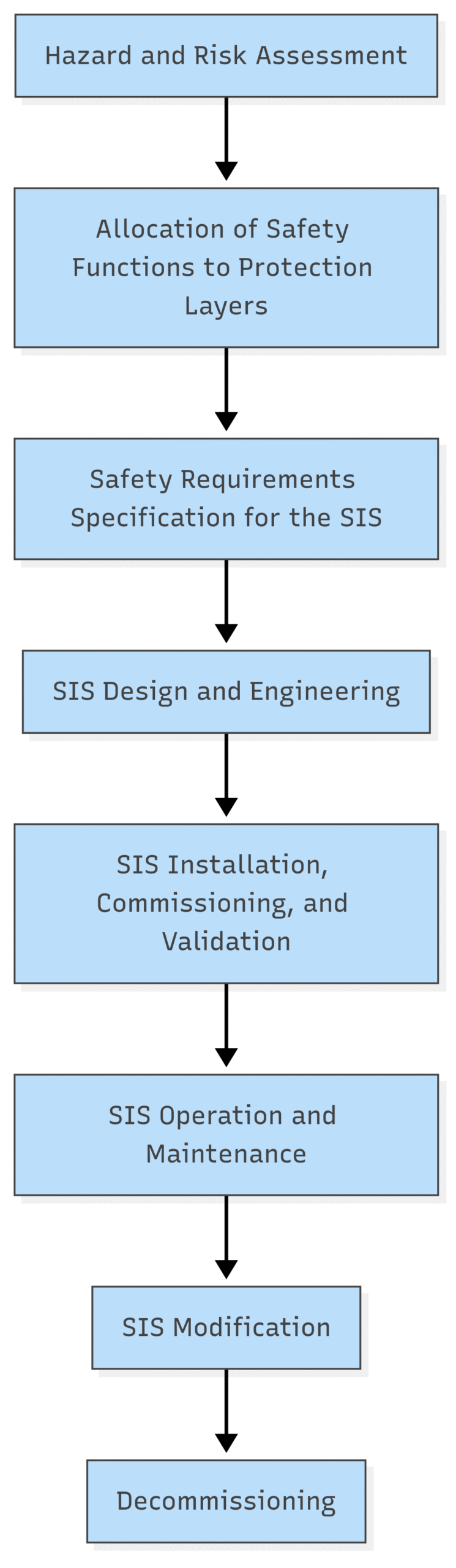
Phase 1: Hazard and Risk Assessment – Identifying the “What Ifs”
The first crucial step was a comprehensive Hazard and Operability (HAZOP) study. This systematic review brought together a multi-disciplinary team of process engineers, operations personnel, safety specialists, and instrumentation engineers. The team meticulously examined each process unit within the refinery, from the crude distillation unit to the hydrocracker and catalytic reformers.
Key Activities:
Process Decomposition: The refinery was broken down into manageable nodes or sections.
Guideword Application: The team applied standard HAZOP guidewords (e.g., No Flow, More Pressure, Less Temperature) to identify potential deviations from the design intent.
Consequence and Cause Analysis: For each deviation, the team identified the potential consequences (e.g., fire, explosion, toxic release) and their credible causes.
The HAZOP study generated a vast list of hazardous scenarios. The next step was to quantify the risk associated with each scenario using a Layer of Protection Analysis (LOPA).
LOPA in Action: LOPA is a semi-quantitative risk assessment method that helps determine the required risk reduction for a given hazardous scenario. It evaluates the effectiveness of independent protection layers (IPLs) in preventing an incident.
Block Diagram: Layer of Protection Analysis (LOPA)
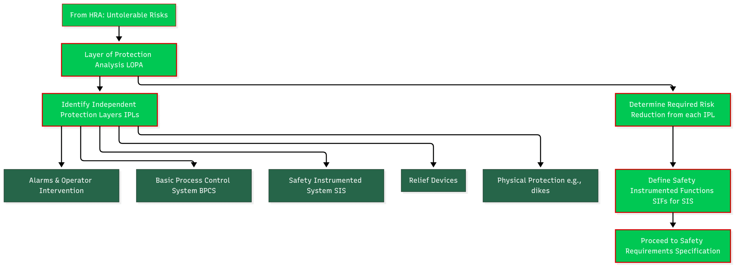
For each scenario, the team assigned a target frequency for the consequence. By taking credit for the risk reduction provided by the existing IPLs, the required SIL for the Safety Instrumented Function (SIF) was determined.
Phase 2: Safety Requirements Specification (SRS) – Defining the “How”
Once the necessary SIFs and their corresponding SILs were identified, the project moved into the Safety Requirements Specification (SRS) phase. The SRS is a critical document that details the functional and integrity requirements for each SIF. A poorly defined SRS can lead to an ineffective or overly expensive SIS.
Key Elements of the SRS:
A clear description of the SIF’s safety function.
The identified hazardous event and the process conditions that trigger the SIF.
The required SIL for the SIF.
The safe state of the process.
The required process response time.
Requirements for manual shutdown, proof testing, and maintenance overrides.
The demand rate on the SIF.
The development of the SRS was an iterative process, requiring close collaboration between the process safety team and the instrumentation and control engineers.
Phase 3: SIS Design and Engineering – Bringing the Safety Net to Life
With a comprehensive SRS in hand, the design of the SIS could commence. This phase involved selecting the appropriate hardware and software and designing the architecture to meet the specified SILs.
Key Design Considerations:
Component Selection: Sensors, logic solvers (safety PLCs), and final elements (e.g., emergency shutdown valves) were selected from certified and “proven in use” equipment catalogs. The selection process prioritized reliability, diagnostic coverage, and resistance to common cause failures.
Architectural Design: The architecture of each SIF was designed to achieve the target SIL. This often involved implementing redundancy (e.g., 1-out-of-2 or 2-out-of-3 voting) for critical components to enhance fault tolerance.
Separation and Segregation: The SIS was designed to be physically and logically separate from the Basic Process Control System (BPCS) to prevent a single point of failure from compromising both control and safety functions.
Cybersecurity: In today’s interconnected world, cybersecurity is an integral part of functional safety. The SIS network was isolated from the plant’s business network, and robust access control measures were implemented.
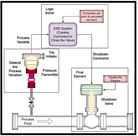
Block Diagram: A Typical Safety Instrumented Function (SIF) Loop
Challenge Spotlight: The High-Integrity Pressure Protection System (HIPPS)
One of the most critical SIFs in the refinery was the High-Integrity Pressure Protection System (HIPPS) for a high-pressure reactor. The LOPA determined a SIL 3 requirement for this function.
Solution:
Sensors: Three independent and diverse pressure transmitters were installed in a 2-out-of-3 voting arrangement.
Logic Solver: A certified SIL 3 safety PLC was used.
Final Elements: Two quick-closing, tight-shutoff valves were installed in series. Partial stroke testing capabilities were included to allow for online testing of the valves without disrupting the process.
This robust design ensured a very high level of reliability and availability for this critical safety function.
Phase 4: Installation, Commissioning, and Validation – Proving its Worth
The meticulous design was followed by a rigorous installation, commissioning, and validation phase. This was not a “plug and play” exercise; it required a systematic approach to ensure that the installed SIS met the requirements of the SRS.
Key Activities:
Factory Acceptance Test (FAT): The integrated SIS was thoroughly tested at the vendor’s facility before being shipped to the site.
Site Acceptance Test (SAT): Once installed, the SIS was tested again to ensure that no damage occurred during transportation and installation.
Loop-by-Loop Validation: Each SIF was tested from the sensor to the final element to verify its functionality and response time. This included simulating process deviations to trigger the SIF.
Documentation Review: All design and testing documentation was reviewed to ensure completeness and accuracy.
A key output of this phase was the Functional Safety Assessment (FSA), an independent review to confirm that the SIS, as installed, was fit for purpose and met the requirements of IEC 61511.
Phase 5: Operation, Maintenance, and Continuous Improvement
The implementation of functional safety does not end with commissioning. The ongoing operation and maintenance of the SIS are critical to ensuring its integrity throughout the lifecycle of the refinery.
Key Elements of the Operational Phase:
Competency Management: Operations and maintenance personnel received comprehensive training on the purpose, functionality, and testing procedures for the SIS.
Proof Testing: Regular proof tests were scheduled to detect any covert failures in the SIF components. The frequency of these tests was determined based on the SIL of the SIF and the reliability data of its components.
Management of Change (MoC): A strict MoC procedure was implemented to ensure that any changes to the process, the BPCS, or the SIS itself were carefully evaluated for their impact on functional safety.
Data Collection and Analysis: All demands on the SIS, as well as any failures or spurious trips, were recorded and analyzed. This data provided valuable feedback for optimizing maintenance strategies and identifying potential systemic issues.
Conclusion: A Culture of Safety by Design
The successful implementation of functional safety in the Greenfield Refinery Project was not simply a matter of compliance; it was a fundamental commitment to a culture of safety by design. By embracing the principles of the IEC 61511 safety lifecycle, the project team was able to systematically identify, assess, and mitigate process risks.
The key takeaways from this case study are:
Early Integration: Functional safety must be considered from the earliest stages of a project.
Multidisciplinary Collaboration: A successful functional safety program requires the active participation of all relevant disciplines.
Rigorous Adherence to Standards: International standards provide a proven framework for achieving a high level of safety.
Lifecycle Perspective: Functional safety is an ongoing process that extends from conception to decommissioning.
By investing in a robust functional safety program, the Greenfield Refinery Project not only ensured regulatory compliance but also laid the foundation for safe, reliable, and profitable operations for decades to come. The block diagrams of the safety lifecycle, LOPA, and a typical SIF loop serve as simplified yet powerful illustrations of the structured and systematic approach that underpins modern process safety. This case study demonstrates that in the high-stakes world of refining, a proactive and comprehensive approach to functional safety is not just an option; it is an absolute necessity.