
Designing Secure Instrumentation Architectures per IEC 62443: A Practical Guide
In the intricate and interconnected world of industrial automation, the security of instrumentation and control systems is no longer an afterthought but a critical necessity. As operational technology (OT) and information technology (IT) converge, the once-isolated networks of sensors, actuators, and controllers are now potential entry points for cyber threats. The IEC 62443 standard has emerged as the leading framework for securing industrial automation and control systems (IACS), providing a comprehensive methodology for asset owners, system integrators, and product manufacturers. This blog post will delve into the practical application of IEC 62443 for designing secure instrumentation architectures, complete with illustrative block diagrams to guide you through the process.
The Imperative for Secure Instrumentation Architectures
The instrumentation layer, encompassing sensors, transmitters, actuators, and their associated controllers, forms the bedrock of any industrial process. These devices are the eyes, ears, and hands of the operation, gathering critical data and executing precise control actions. A compromise at this level can have devastating consequences, leading to production downtime, equipment damage, environmental incidents, and even threats to human safety.
Traditionally, the security of instrumentation was often addressed through physical separation, the so-called “air gap.” However, the drive for enhanced efficiency, remote monitoring, and data analytics has led to increased connectivity, effectively bursting this bubble. This heightened exposure necessitates a structured and robust approach to cybersecurity, which is precisely what IEC 62443 offers.
Core Concepts of IEC 62443 for Instrumentation Security
Before diving into architectural design, it’s crucial to grasp the fundamental concepts of IEC 62443 that are most relevant to instrumentation.
Zones and Conduits: The Foundation of Segmentation
The cornerstone of a secure IACS architecture under IEC 62443 is the concept of zones and conduits.
Zones are logical groupings of assets that share common security requirements. In an instrumentation context, a zone could be a set of critical sensors and actuators associated with a specific process unit, or a group of safety instrumented systems (SIS). By grouping these assets, you can apply consistent security policies and controls.
Conduits are the communication pathways between zones. Every connection to and from a zone must be via a defined conduit. This allows for the targeted application of security controls to manage data flow and prevent unauthorized access. For example, the connection between a PLC (Programmable Logic Controller) in a control zone and a set of smart sensors in a field zone would be a conduit.
Security Levels (SLs): Defining the Target for Security
IEC 62443 introduces the concept of Security Levels (SLs) to specify the required robustness of security controls. There are five security levels, ranging from SL 0 (no specific requirements) to SL 4 (protection against nation-state-level attacks). The determination of the target security level (SL-T) for a zone or conduit is a risk-based decision.
For a typical instrumentation architecture, the SL-T will depend on factors such as:
The criticality of the process being controlled.
The potential safety, environmental, and financial impact of a security breach.
The likelihood of a successful attack.
For instance, a zone containing basic, non-critical monitoring sensors might be assigned an SL-T of 1 or 2, while a zone with safety-critical shutdown valves would warrant a higher SL-T, such as 3.
Architecting a Secure Instrumentation Network: A Step-by-Step Approach with Block Diagrams
Building a secure instrumentation architecture is a systematic process. The following steps, aligned with the principles of IEC 62443 and the widely adopted Purdue Model for Control Hierarchy, provide a practical roadmap.
The Purdue Model: A Framework for IACS Architecture
The Purdue Model provides a foundational framework for segmenting IACS environments into logical levels. For instrumentation, we are primarily concerned with the lower levels:
Level 0: The Process: This level includes the physical equipment—motors, valves, sensors, etc.
Level 1: Basic Control: This level comprises the devices that sense and manipulate the process, such as sensors, actuators, and PLCs.
Level 2: Area Supervisory Control: This level includes the systems responsible for supervising and operating a specific area of the plant, such as Human-Machine Interfaces (HMIs) and supervisory control systems.
Step 1: Asset Inventory and Initial Risk Assessment
The first step is to create a comprehensive inventory of all instrumentation assets. This includes:
Sensors (e.g., pressure, temperature, flow transmitters)
Actuators (e.g., control valves, motors)
Controllers (e.g., PLCs, RTUs)
Local HMIs
Network infrastructure (e.g., switches, gateways)
Once you have your asset inventory, perform an initial high-level risk assessment to identify the most critical instrumentation systems. This will help you prioritize your security efforts.
Step 2: Defining Zones and Conduits at the Instrumentation Level
Based on your asset inventory and risk assessment, you can begin to partition your instrumentation architecture into zones and conduits.
Example: A Simple Process Control Zone
Consider a basic process unit with a set of sensors, a PLC, and a local HMI. We can define this as a “Process Control Zone.”
Block Diagram 1: A Basic (Insecure) Instrumentation Architecture
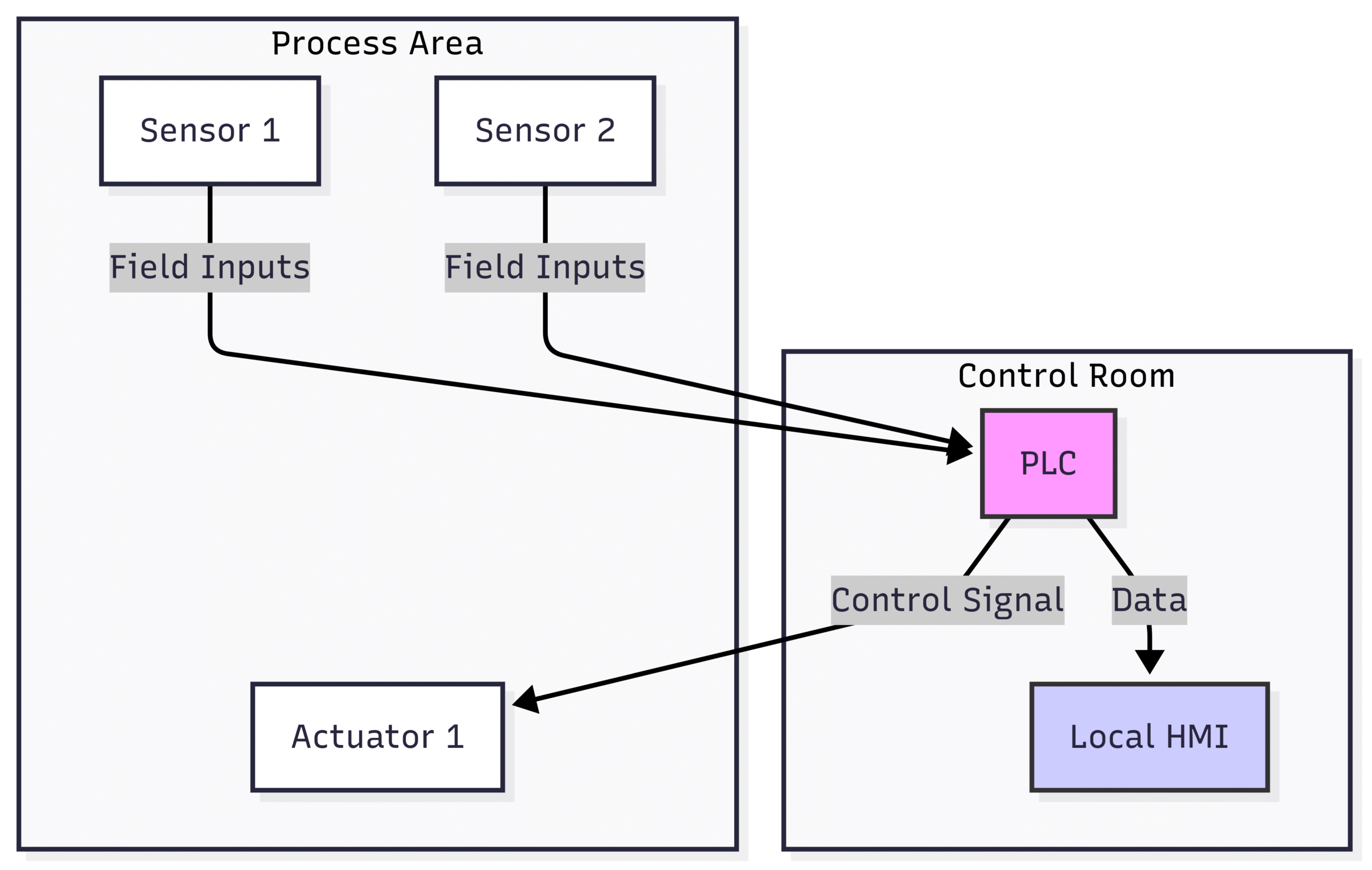
This initial diagram shows the basic connectivity. Now, let’s apply the concept of zones and conduits.
Block Diagram 2: Applying Zones and Conduits
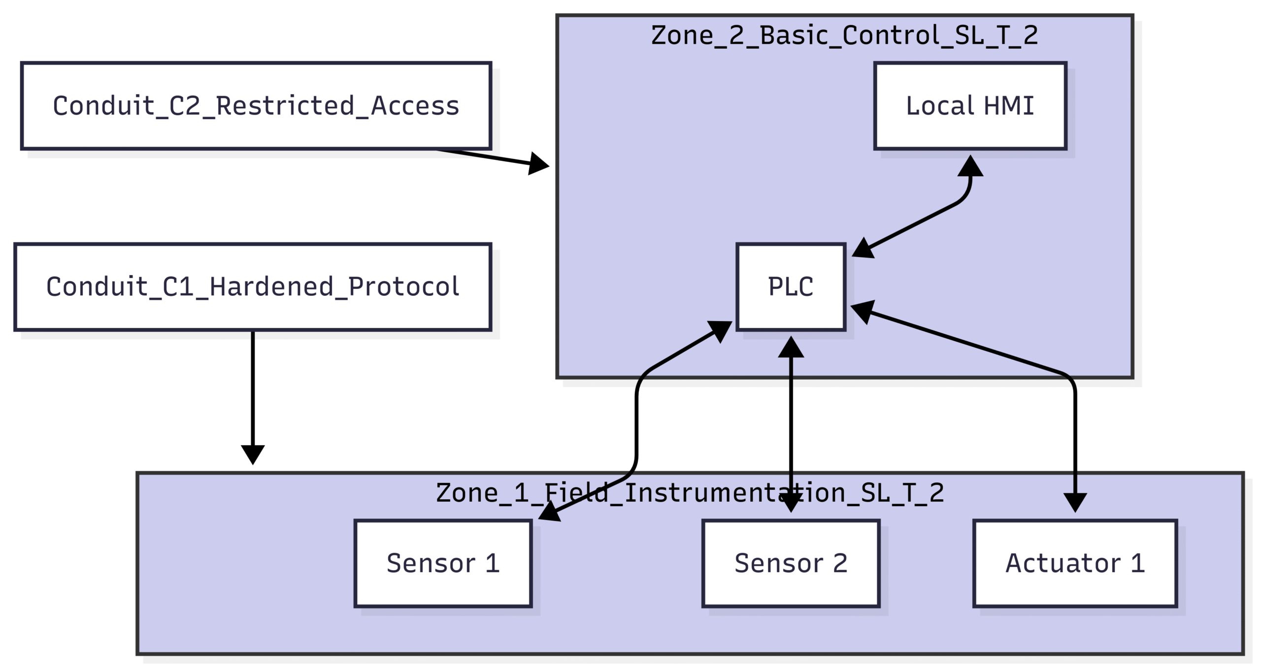
In this secure architecture:
We have created two distinct zones: Zone 1 for the field devices and Zone 2 for the control components. Both have a target security level of 2.
The communication between the PLC and the field devices is now defined as Conduit C1. This conduit should be secured, for example, by using a hardened communication protocol and ensuring physical protection of the cabling.
The connection between the HMI and the PLC is Conduit C2, which should have restricted access controls to prevent unauthorized modifications to the PLC logic.
Step 3: Implementing a Defense-in-Depth Strategy
A core principle of IEC 62443 is defense-in-depth. This means implementing multiple layers of security controls so that if one layer is breached, others are in place to thwart an attack.
Hardening Individual Devices:
PLCs: Change default passwords, disable unused ports and services, and implement access control lists (ACLs) to restrict connections.
Smart Sensors and Actuators: If they have embedded web servers or configuration interfaces, ensure they are password-protected and that firmware is kept up to date.
Network Switches: Use managed switches that allow for port security, VLANs (Virtual Local Area Networks), and traffic monitoring.
Network Segmentation and Firewalls:
For more complex architectures, you will have multiple zones. Firewalls are essential for enforcing security policies at the boundaries of these zones.
Block Diagram 3: A Multi-Zone Instrumentation Architecture with a Demilitarized Zone (DMZ)

This more advanced architecture demonstrates several key security concepts:
Clear Segmentation: The architecture is clearly divided into zones based on function and criticality. The critical process control (Zone 2 and Zone 1) has a higher SL-T.
Demilitarized Zone (DMZ): A DMZ is established between the enterprise network and the control network. This acts as a buffer, preventing direct communication and providing a location for shared services like a data historian. All remote access should be funneled through a secure jump server in the DMZ.
Controlled Conduits: Each conduit has specific security controls. For example, the conduit from the DMZ to the control network might be restricted to read-only access for the data historian, preventing any attempt to send malicious commands from the enterprise network.
Step 4: Secure Remote Access
Remote access is a common requirement but also a significant vulnerability. IEC 62443 provides guidance on securing remote access.
Use a Bastion Host or Jump Server: All remote access should be routed through a dedicated, hardened server in the DMZ.
Multi-Factor Authentication (MFA): Implement MFA for all remote users.
Role-Based Access Control (RBAC): Grant users only the permissions they need to perform their jobs.
Encrypted Connections: Use strong encryption protocols like TLS or IPsec for all remote connections.
Step 5: Continuous Monitoring and Maintenance
Cybersecurity is not a one-time project. It requires ongoing vigilance.
Intrusion Detection Systems (IDS): Deploy IDS that are specifically designed for industrial protocols to monitor for anomalous traffic within the instrumentation network.
Log Management: Collect and analyze logs from firewalls, switches, PLCs, and other devices to detect potential security incidents.
Patch Management: Develop a robust process for testing and deploying security patches for all instrumentation components. This should be done in a controlled manner to avoid disrupting operations.
Regular Audits and Assessments: Periodically review your instrumentation architecture and security controls to ensure they remain effective against evolving threats.
Conclusion: Building a Resilient Future for Industrial Operations
Designing secure instrumentation architectures in accordance with IEC 62443 is an essential undertaking for any modern industrial organization. By embracing the concepts of zones and conduits, conducting thorough risk assessments to determine appropriate security levels, and implementing a defense-in-depth strategy, you can build a resilient foundation for your operations.
The journey towards a secure instrumentation architecture requires a holistic approach that considers people, processes, and technology. It’s about fostering a culture of security awareness, implementing robust technical controls, and remaining vigilant in the face of an ever-changing threat landscape. The block diagrams provided in this guide offer a starting point for visualizing and implementing these concepts in your own environment. By taking a proactive and structured approach to instrumentation security, you can safeguard your critical assets, ensure operational continuity, and build a more secure and resilient future for your industrial enterprise.