In industrial automation, accurate and reliable transmission of process data is critical. One of the most widely used methods for transmitting analog signals in process control systems is the 4-20 mA current loop. This article will provide an in-depth explanation of how a process variable, such as pressure, temperature, level, or flow, is converted into a 4-20 mA signal. It will also explore the electronics involved in a transmitter and the role of a 250-ohm resistor in this setup.
- Introduction to Process Variables
A process variable (PV) is a measurable condition of a process, such as:
- Pressure (in bar, psi, etc.)
- Temperature (in °C, °F)
- Flow (in m3/hr, LPM)
- Level (in %, meters)
In process plants, sensors measure these variables, and the measured signal is converted into a standardized analog signal, most commonly 4-20 mA.
- Why Use 4-20 mA Instead of Voltage?
Advantages:
- Less noise interference: Current is less susceptible to signal loss and electromagnetic interference.
- Long distance transmission: Signals can travel hundreds of meters without degradation.
- Live zero: 4 mA (not 0 mA) represents the minimum measurement, allowing for sensor fault detection.
- Simplicity: Loop-powered devices can be powered and controlled with just two wires.
- Anatomy of a Transmitter
A transmitter is an electronic device that converts the output from a sensor (such as a thermocouple, RTD, strain gauge, or differential pressure sensor) into a standard current output signal (4-20 mA).
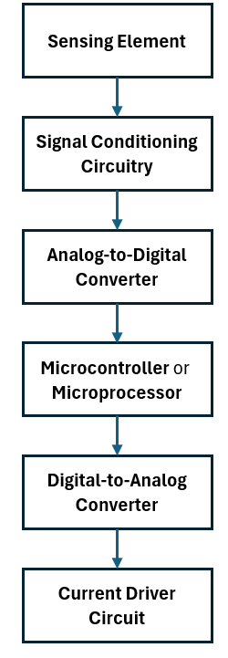
Typical Transmitter Architecture:
- Sensing Element
- Signal Conditioning Circuitry
- Analog-to-Digital Converter (ADC) (in smart transmitters)
- Microcontroller or Microprocessor
- Digital-to-Analog Converter (DAC)
- Current Driver Circuit
- Step-by-Step Conversion Process
Step 1: Sensor Measures the Process Variable
A sensor (e.g., RTD or strain gauge) generates a small analog voltage or resistance change based on the process variable.
Step 2: Signal Conditioning
The sensor output is often very small or nonlinear. The signal conditioning circuit amplifies and linearizes the signal:
- Amplification to increase signal strength
- Filtering to remove noise
- Linearization to correct non-linear sensor outputs
Step 3: Analog to Digital Conversion (if smart transmitter)
An ADC converts the conditioned analog signal into a digital value for microcontroller processing.
Step 4: Microcontroller Processing
The microcontroller compares the signal against calibrated range:
For example:
- 0 to 100 °C = 4 to 20 mA
- If sensed value is 50 °C, then the equivalent output should be:
Step 5: Digital to Analog Conversion
A DAC converts the calculated digital signal into a voltage which is then used to control the current driver.
Step 6: Current Driver Circuit
This circuit converts the DAC voltage into a regulated current source. The design ensures the loop current matches the desired signal (4-20 mA) regardless of load impedance within permissible limits.
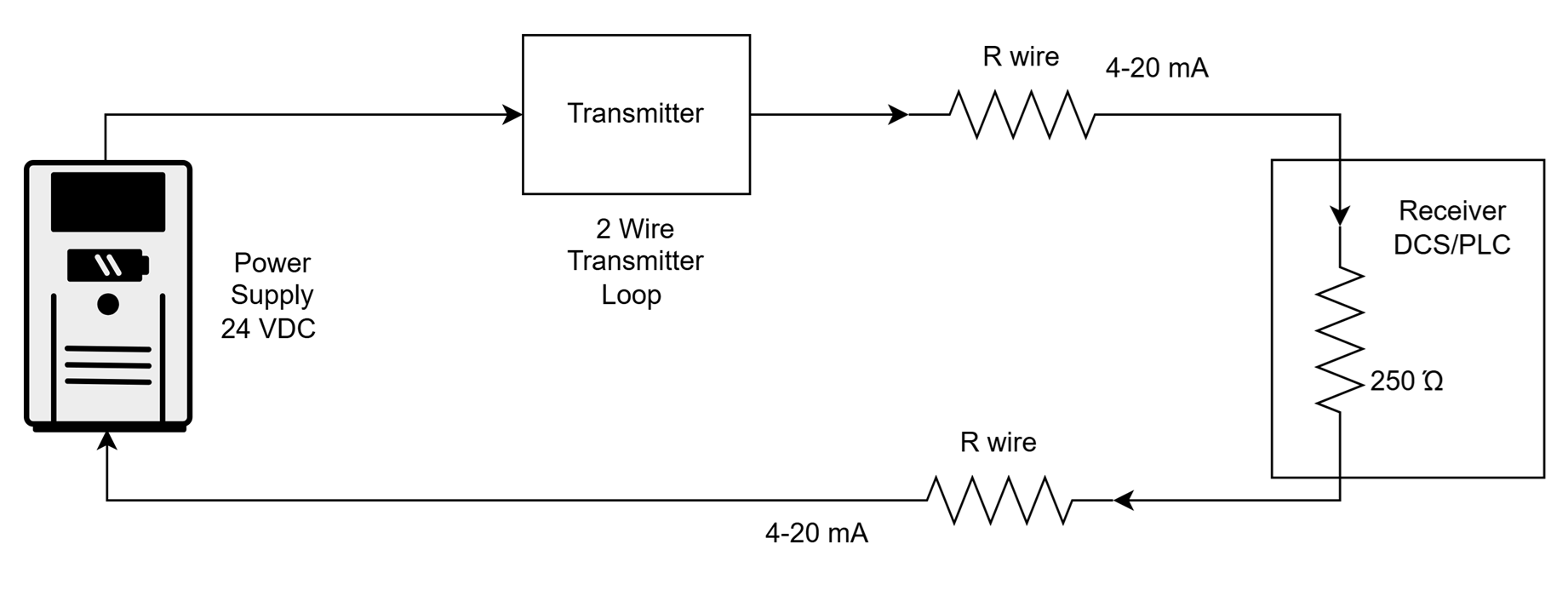
- 4-20 mA Loop Configuration
Basic Loop Elements:
- Power Supply (typically 24V DC)
- Transmitter (loop-powered or 2-wire)
- Signal wire (twisted pair cable)
- Receiving device (PLC/Controller or DCS input card)
- 250-ohm resistor (if voltage input is required)
- Role of 250-Ohm Resistor
The 250-ohm resistor is often used in analog input cards of PLCs or DCS where the input is voltage-based (1-5V) rather than current-based. Since:
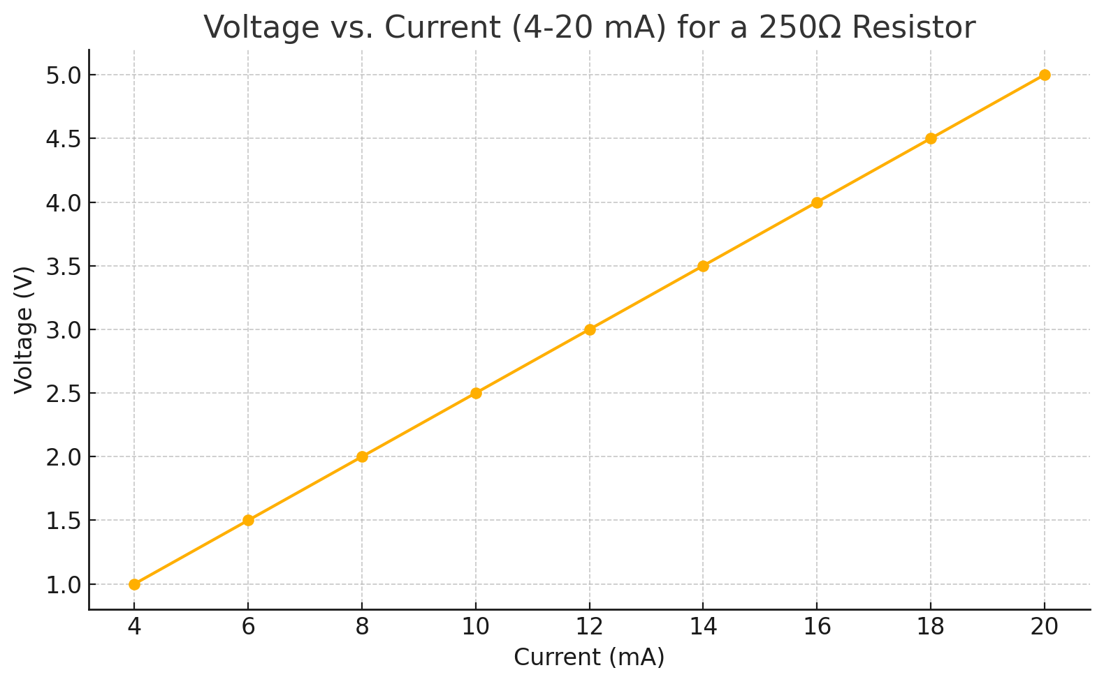
A 4-20 mA current passing through a 250-ohm resistor will generate:
- 4 mA * 250 ohm = 1 V
- 20 mA * 250 ohm = 5 V
Thus, the voltage across the resistor represents the current level and hence the process variable.
This allows current-loop signals to be read by voltage-input analog devices.
- Transmitter Power Supply Considerations
The power supply must provide:
- Enough voltage to overcome the voltage drops due to:
- Transmitter internal electronics
- Wire resistance
- Any resistors or input impedances
Voltage budget calculation:
- Transmitter drop = 10 V typical
- Input impedance = 250 ohms = 5V max
- Cable drop = minimal (~1V)
- Total = 16V
- Supply = 24V provides a safe margin
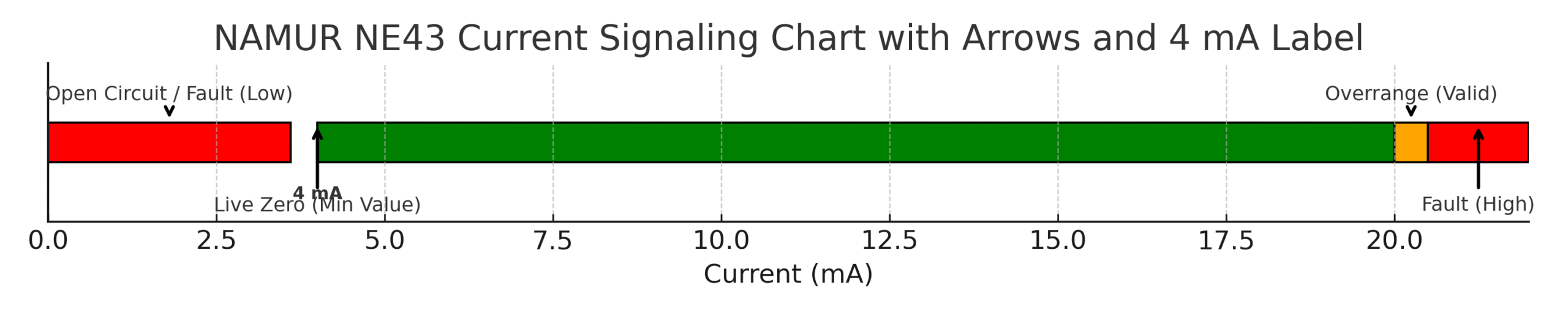
- Fault Detection and Live Zero
Using 4 mA instead of 0 mA for the lowest signal (live zero) allows systems to:
- Detect open loop (0 mA = fault)
- Differentiate between signal failure and low measurement
- Support diagnostics (NAMUR NE43 uses <3.6 mA or >21 mA for fault indication)
- Loop Calibration and Ranging
Ranging:
Configure the transmitter to interpret:
- 0% PV = 4 mA
- 100% PV = 20 mA
This is set using HART communicator, DIP switches, or software.
Calibration:
Ensure actual output matches expected current for given PV using:
- Calibration source (e.g., pressure calibrator)
- Multimeter or loop calibrator
- Conclusion
The 4-20 mA current loop remains the backbone of industrial instrumentation due to its simplicity, robustness, and ability to operate in electrically noisy environments. Understanding how the process variable is sensed, conditioned, digitized, and converted into a proportional 4-20 mA signal enables engineers to design and troubleshoot systems effectively.
The 250-ohm resistor plays a crucial role in interfacing current loops with voltage-input devices. By mastering these fundamentals, instrumentation engineers can ensure accurate and reliable data transmission across all stages of process control.