
Level Measurement in Oil & Gas: A Complete Guide to Technologies and Applications
In the sprawling and high-stakes world of the oil and gas industry, precision is paramount. From the volatile depths of exploration and production to the vast storage terminals and complex refining processes, the accurate measurement of liquid and gas levels is a critical function that underpins safety, operational efficiency, and environmental protection. This comprehensive guide delves into the diverse technologies and applications of level measurement, offering a roadmap for understanding this vital aspect of the oil and gas sector.
The uninterrupted and accurate measurement of levels in tanks, separators, and other vessels is not merely a matter of inventory management. It is a cornerstone of process control, preventing costly overfills, ensuring the integrity of equipment, and safeguarding personnel from hazardous incidents. In an industry where margins are tight and regulations are stringent, optimizing every stage of the production and distribution chain is essential. This is where advanced level measurement technologies play a pivotal role, providing the real-time data needed for informed decision-making.
This blog will explore the leading non-contacting and contacting level measurement technologies, from the sophisticated radar and ultrasonic systems to the robust and reliable hydrostatic and magnetic gauges. We will examine their working principles with the help of clear block diagrams, weigh their advantages and disadvantages, and pinpoint their most effective applications across the upstream, midstream, and downstream sectors. Furthermore, we will shed light on advanced applications like custody transfer and interface level measurement, and address the unique challenges the oil and gas environment presents.
Non-Contacting Level Measurement: Peering from a Distance
Non-contacting level measurement technologies offer the significant advantage of not having to touch the process medium. This makes them ideal for aggressive, corrosive, or high-purity substances and reduces maintenance requirements.
Radar Level Measurement: The All-Seeing Eye
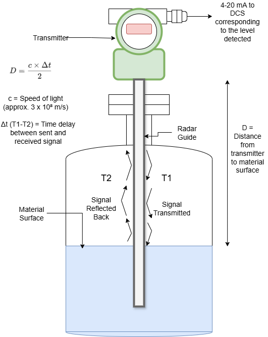
Radar level transmitters have become a go-to technology in the oil and gas industry due to their high accuracy and reliability in a wide range of conditions. They operate by emitting a high-frequency microwave pulse from an antenna at the top of a tank. This pulse travels down, reflects off the surface of the liquid or solid, and is received back by the antenna.
Working Principle:
The core principle behind radar level measurement is the time-of-flight (ToF) of the microwave pulse. The transmitter’s electronics calculate the distance to the material surface based on the time it takes for the pulse to travel to the liquid and back. The level is then determined by subtracting this distance from the known height of the tank.
Distance = (Speed of Light x Time Delay) / 2
Level = Tank Height – Distance
Two main types of radar technology are used:
Pulsed Radar: Transmits short bursts of microwave energy and measures the time until the echo returns.
Frequency Modulated Continuous Wave (FMCW) Radar: Transmits a continuous signal with a linearly varying frequency. The difference in frequency between the transmitted and received signals is proportional to the distance to the liquid surface. FMCW radars are known for their high accuracy and ability to perform well even with weak reflections.
Block Diagram of a Radar Level Transmitter:
Advantages:
High Accuracy and Reliability: Radar signals are largely unaffected by changes in temperature, pressure, gas composition, or vapor.
No Moving Parts: This leads to low maintenance requirements and a long operational life.
Non-Contact Measurement: Suitable for corrosive, viscous, and abrasive materials.
Can Measure Through Foam: Advanced signal processing allows many radar transmitters to filter out false echoes from foam.
Suitable for a Wide Range of Applications: Can be used for liquids, slurries, and some solids.
Disadvantages:
Higher Initial Cost: Compared to some other technologies.
Dielectric Constant Dependency: The reflectivity of the microwave signal depends on the dielectric constant of the medium. Low dielectric constant materials (e.g., some hydrocarbons) can result in weaker reflections.
Potential for Dead Zones: There is typically a small “dead zone” at the top of the tank where the transmitter cannot make an accurate measurement.
Applications in Oil & Gas:
Storage Tank Gauging: For crude oil, refined products (gasoline, diesel), and other hydrocarbons in large atmospheric and pressurized storage tanks.
Process Vessels: Monitoring levels in reactors, distillation columns, and other process vessels in refineries and chemical plants.
Separators: Measuring the level of oil, gas, and water in three-phase separators.
LNG and LPG Tanks: Specialized radar transmitters are designed for the cryogenic temperatures of liquefied natural gas and petroleum gas.
Ultrasonic Level Measurement: Sounding Out the Level
Ultrasonic level transmitters operate on a similar time-of-flight principle to radar but use high-frequency sound waves instead of microwaves. A transducer mounted at the top of the tank emits a burst of ultrasonic pulses. These pulses travel through the gas or vapor space, reflect off the liquid surface, and are detected by the same transducer.
Working Principle:
The time it takes for the ultrasonic pulse to travel to the liquid and back is measured. The instrument’s electronics then calculate the distance to the surface, and subsequently the level.
Distance = (Speed of Sound x Time Delay) / 2
Level = Tank Height – Distance
The speed of sound through the gas or vapor above the liquid is a critical factor and can be affected by changes in temperature and pressure. Therefore, many ultrasonic transmitters have a built-in temperature sensor to compensate for these variations.
Block Diagram of an Ultrasonic Level Transmitter:

Advantages:
Cost-Effective: Generally more affordable than radar transmitters.
Non-Contact Measurement: Suitable for a variety of liquids.
Easy to Install and Configure: Simple setup and calibration procedures.
No Moving Parts: Low maintenance requirements.
Disadvantages:
Affected by Environmental Conditions: Changes in temperature, pressure, and gas composition can affect the speed of sound and therefore the accuracy of the measurement.
Not Suitable for Vacuums: Ultrasonic waves cannot travel in a vacuum.
Susceptible to Interference: Foam, heavy vapors, dust, and turbulence can scatter or absorb the ultrasonic signal, leading to inaccurate readings.
Limited Pressure and Temperature Range: The performance of the transducer can be affected by extreme temperatures and pressures.
Applications in Oil & Gas:
Chemical Storage Tanks: Monitoring the levels of various chemicals used in processing and water treatment.
Water and Wastewater Treatment: Measuring levels in open channels, sumps, and storage tanks.
Less Critical Storage Applications: For materials where high accuracy is not the primary concern.
Drilling Mud Tanks: Monitoring the level of drilling fluids on rigs.
Contacting Level Measurement: Getting a Direct Feel
Contacting level measurement technologies involve a sensor that is in direct contact with the process fluid. While this can introduce some challenges, these methods are often robust, reliable, and cost-effective for many applications.
Hydrostatic Level Measurement: The Pressure Principle
Hydrostatic level measurement is one of the oldest and most widely used methods for determining the level of a liquid in a tank. It is based on the principle that the pressure exerted by a column of liquid is directly proportional to the height of the liquid.
Working Principle:
A pressure transmitter is installed at or near the bottom of the tank. The transmitter measures the hydrostatic pressure exerted by the liquid column above it. This pressure reading is then converted into a level measurement.
Pressure = Height x Density x Gravitational Constant
Height (Level) = Pressure / (Density x Gravitational Constant)
The accuracy of hydrostatic level measurement is dependent on the liquid’s density remaining constant. If the density changes with temperature or composition, a density compensation method is required for accurate level readings.
For vented tanks (open to the atmosphere), a simple gauge pressure transmitter is sufficient. For pressurized or sealed tanks, a differential pressure (DP) transmitter is used. The DP transmitter measures the difference between the pressure at the bottom of the tank (hydrostatic head + gas pressure) and the pressure of the gas or vapor at the top of the tank. This effectively cancels out the effect of the gas pressure, leaving only the hydrostatic pressure of the liquid.
Block Diagram of a Hydrostatic Level Measurement System (Pressurized Tank):

Advantages:
Robust and Reliable: Well-established and proven technology.
Cost-Effective: Often a more economical solution for many applications.
Not Affected by Foam or Vapors: The measurement is based on pressure, so surface conditions have no impact.
Suitable for a Wide Range of Liquids: Can be used with most liquids, including those that are turbulent or agitated.
Disadvantages:
Density Dependent: Changes in liquid density will affect the accuracy of the level measurement.
Contact with Process Fluid: The sensor is in direct contact with the medium, which can be an issue for corrosive or abrasive materials.
Potential for Clogging: The pressure sensing diaphragm can become clogged in applications with suspended solids or sludge.
Applications in Oil & Gas:
Ballast Tanks on Offshore Platforms: Measuring the level of seawater in ballast tanks for stability control.
Fuel Storage Tanks: Monitoring the level of diesel and other fuels.
Water Storage and Treatment: For various water storage and processing applications.
Well Fluid Holding Tanks: Measuring the level of produced water and other well fluids.
Magnetic Level Indicators: A Visual and Reliable Solution
Magnetic level indicators (MLIs), also known as magnetic level gauges, provide a simple, robust, and highly reliable method for local visual indication of liquid levels. They are often used in conjunction with other level transmitters to provide a redundant and easily verifiable measurement.
Working Principle:
An MLI consists of a chamber that is connected to the side of the tank. Inside this chamber is a float containing a powerful magnet. As the liquid level in the tank rises and falls, the float moves up and down accordingly. On the outside of the chamber is a visual indicator, which typically consists of a series of colored flags or a follower that is magnetically coupled to the float. As the float moves, the magnets cause the flags to flip, providing a clear visual indication of the liquid level.
Block Diagram of a Magnetic Level Indicator:
+----------------+      +---------------------+
|      Tank      |------|     Float Chamber   |
| (Process Fluid)|      | (with Magnetic Float)|
+----------------+      +---------------------+
                            | Magnetically Coupled
                            v
                  +---------------------+
                  |   Visual Indicator  |
                  | (Colored Flags or   |
                  |      Follower)      |
                  +---------------------+
Advantages:
High Visibility: Provides a clear and easy-to-read local indication of the liquid level.
Robust and Reliable: Simple mechanical design with no power required for the basic visual indicator.
Safe for High-Pressure and High-Temperature Applications: The process fluid is contained within the chamber, isolating it from the visual indicator.
Can be Equipped with Transmitters and Switches: MLIs can be fitted with magnetostrictive or other types of level transmitters to provide a continuous electronic output, as well as high and low-level alarm switches.
Disadvantages:
Contact with Process Fluid: The float is in direct contact with the liquid.
Potential for Sticking: The float can potentially stick if the process fluid is dirty or prone to buildup.
Local Indication Only (without transmitter): The basic MLI provides only a local visual indication.
Applications in Oil & Gas:
Boiler Drums: Monitoring the water level in high-pressure boiler drums.
Feedwater Heaters: Providing local level indication in feedwater systems.
Storage Tanks: For local level verification on a wide variety of storage tanks.
Separators and Scrubbers: Monitoring liquid levels in process vessels.
Advanced Applications and Systems
Beyond basic level measurement in a single tank, several advanced applications and systems are critical in the oil and gas industry.
Tank Gauging Systems: The Backbone of Inventory Management
Tank gauging systems are comprehensive solutions for monitoring the inventory of liquids in large storage tanks and tank farms. These systems go beyond a single level measurement and often integrate multiple sensors to provide a complete picture of the stored product.
A typical tank gauging system includes:
High-Accuracy Level Sensor: Often a radar or servo gauge for precise level measurement.
Temperature Sensors: Multiple temperature sensors are placed at different heights within the tank to provide an average temperature of the liquid. This is crucial for volume correction.
Pressure Sensors: For pressurized tanks, pressure sensors are used to measure the vapor pressure.
Water Bottom Sensor: To detect the level of any free water at the bottom of the tank.
Tank Gauging Software: This software collects data from all the sensors, performs calculations (such as volume correction to standard temperatures), and provides a user-friendly interface for inventory management, alarm handling, and reporting.
Custody Transfer:
A critical application of tank gauging systems is custody transfer, which is the measurement of a product being transferred from one party to another for sale. In these applications, accuracy is paramount, and the measurement systems must comply with strict industry standards, such as those from the American Petroleum Institute (API).
Interface Level Measurement: Separating Liquids
In many oil and gas processes, it is necessary to measure the interface level between two immiscible liquids, such as oil and water. This is particularly important in separators, where produced fluids from wells are separated into oil, gas, and water.
Accurate interface level measurement is crucial for:
Optimizing Separator Performance: Ensuring that the oil outlet contains minimal water and the water outlet contains minimal oil.
Preventing Equipment Damage: Preventing water carryover into downstream processing units.
Environmental Compliance: Ensuring that discharged water meets environmental regulations.
Several technologies can be used for interface level measurement, including:
Guided Wave Radar (GWR): GWR is a popular choice for interface measurement. It works by sending a microwave pulse down a probe. Part of the pulse is reflected from the upper liquid surface (e.g., oil), and another part is reflected from the interface between the two liquids (e.g., oil and water). The transmitter can then measure both the overall level and the interface level.
Capacitance Probes: These sensors can detect the interface based on the difference in the dielectric constants of the two liquids.
Displacers: A displacer is a buoyant element that is calibrated to sink in the lighter liquid and float on the heavier liquid, thus indicating the interface level.
Challenges in Oil & Gas Level Measurement
The oil and gas industry presents a unique and demanding set of challenges for level measurement instrumentation.
Harsh Environments: Instruments must be able to withstand extreme temperatures and pressures, from the scorching heat of desert oil fields to the frigid conditions of arctic exploration. Corrosion is also a major concern, requiring the use of specialized materials.
Hazardous Area Classifications: Many areas in oil and gas facilities are classified as hazardous due to the presence of flammable gases and vapors. All electrical equipment, including level transmitters, must be certified for use in these areas (e.g., explosion-proof or intrinsically safe).
Emulsions and Foam: In separators and other process vessels, the formation of emulsions (mixtures of oil and water) and foam can make it difficult for some level measurement technologies to accurately detect the liquid surface. Advanced signal processing and specialized sensor designs are often required.
Adherence to Standards: The industry is heavily regulated, and level measurement systems, particularly those used for custody transfer and safety applications, must comply with a host of standards from organizations like the API.
The Future of Level Measurement: Smarter and More Connected
The future of level measurement in the oil and gas industry is being shaped by digitalization and the Industrial Internet of Things (IIoT). We are seeing a move towards:
Smarter Instruments: Transmitters with advanced diagnostics that can predict potential failures and provide more insights into the process.
Wireless Communication: Wireless technologies like WirelessHART are making it easier and more cost-effective to install level monitoring on remote or difficult-to-reach assets.
Data Analytics: The vast amounts of data generated by level sensors are being used for advanced analytics, enabling predictive maintenance, process optimization, and improved safety.
In conclusion, the accurate and reliable measurement of levels is a fundamental requirement for the safe and efficient operation of the oil and gas industry. From the sophisticated non-contacting technologies like radar and ultrasonic to the robust contacting methods like hydrostatic and magnetic level indicators, a wide range of solutions is available to meet the diverse and demanding applications across the entire value chain. As the industry continues to evolve, so too will the technologies for level measurement, becoming smarter, more connected, and even more critical to success.