
Top 10 Level Measurement Technologies for Oil Storage Applications: A Comprehensive Guide
In the vast and critical landscape of the oil and gas industry, the accurate and reliable measurement of liquid levels in storage tanks is not just a matter of operational efficiency; it’s a cornerstone of safety, environmental protection, and profitability. From massive crude oil reservoirs to refined petroleum product tanks, knowing the precise quantity of stored assets is paramount. The challenge, however, lies in the diverse and often harsh conditions of these storage environments. Factors such as temperature fluctuations, pressure variations, corrosive materials, and the presence of vapors and foam demand a sophisticated approach to level measurement.
This comprehensive guide delves into the top 10 level measurement technologies that have become indispensable in oil storage applications. We will explore their working principles, dissect their advantages and disadvantages, and pinpoint their ideal applications, complete with illustrative block diagrams to demystify their operation. Whether you are a seasoned engineer or new to the field, this article will provide you with the essential knowledge to navigate the complex world of oil storage level measurement.
1. Non-Contact Radar Level Transmitters
Non-contact radar level transmitters have emerged as a dominant technology in the oil and gas industry due to their high accuracy and reliability in a wide range of applications. They are particularly well-suited for the challenging environments of oil storage tanks.
Working Principle
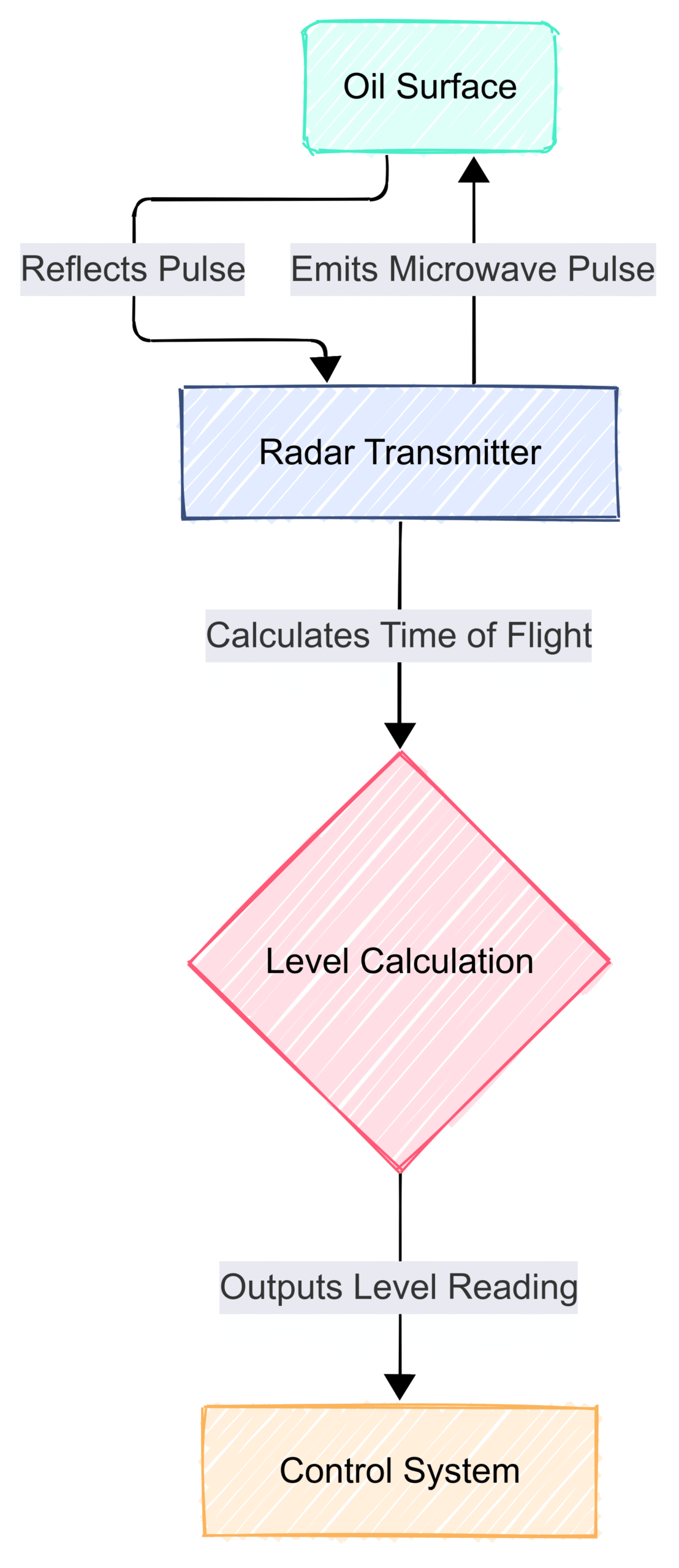
These instruments operate by emitting a high-frequency microwave pulse from an antenna located at the top of the tank. This pulse travels through the vapor space, reflects off the surface of the liquid, and returns to the antenna. The transmitter’s electronics measure the time of flight (the time it takes for the pulse to travel to the liquid surface and back). This time is directly proportional to the distance to the liquid. By subtracting this distance from the total tank height, the liquid level can be precisely calculated.
Block Diagram of a Non-Contact Radar Level Transmitter:
Advantages:
High Accuracy: Radar technology provides precise measurements, often with an accuracy of a few millimeters.
Non-Contact Measurement: As the sensor does not touch the liquid, it is immune to issues related to corrosion, coating, and viscosity.
Unaffected by Process Conditions: Changes in temperature, pressure, and vapor composition have minimal impact on the measurement.
Low Maintenance: The absence of moving parts results in reduced maintenance requirements.
Disadvantages:
Higher Initial Cost: Compared to some other technologies, radar transmitters can have a higher upfront cost.
Signal Interference: In rare cases, heavy foam or turbulence can interfere with the radar signal. However, advanced signal processing algorithms in modern transmitters can often mitigate these effects.
Ideal Applications:
Non-contact radar is ideal for a wide array of oil storage applications, including large crude oil tanks, gasoline and diesel storage tanks, and tanks containing other refined petroleum products. They are particularly effective in tanks with agitators or those prone to vaporous atmospheres.
2. Guided Wave Radar (GWR) Level Transmitters
Guided Wave Radar (GWR) is another prominent radar-based technology that offers exceptional accuracy, especially in applications where non-contact radar might face challenges.
Working Principle
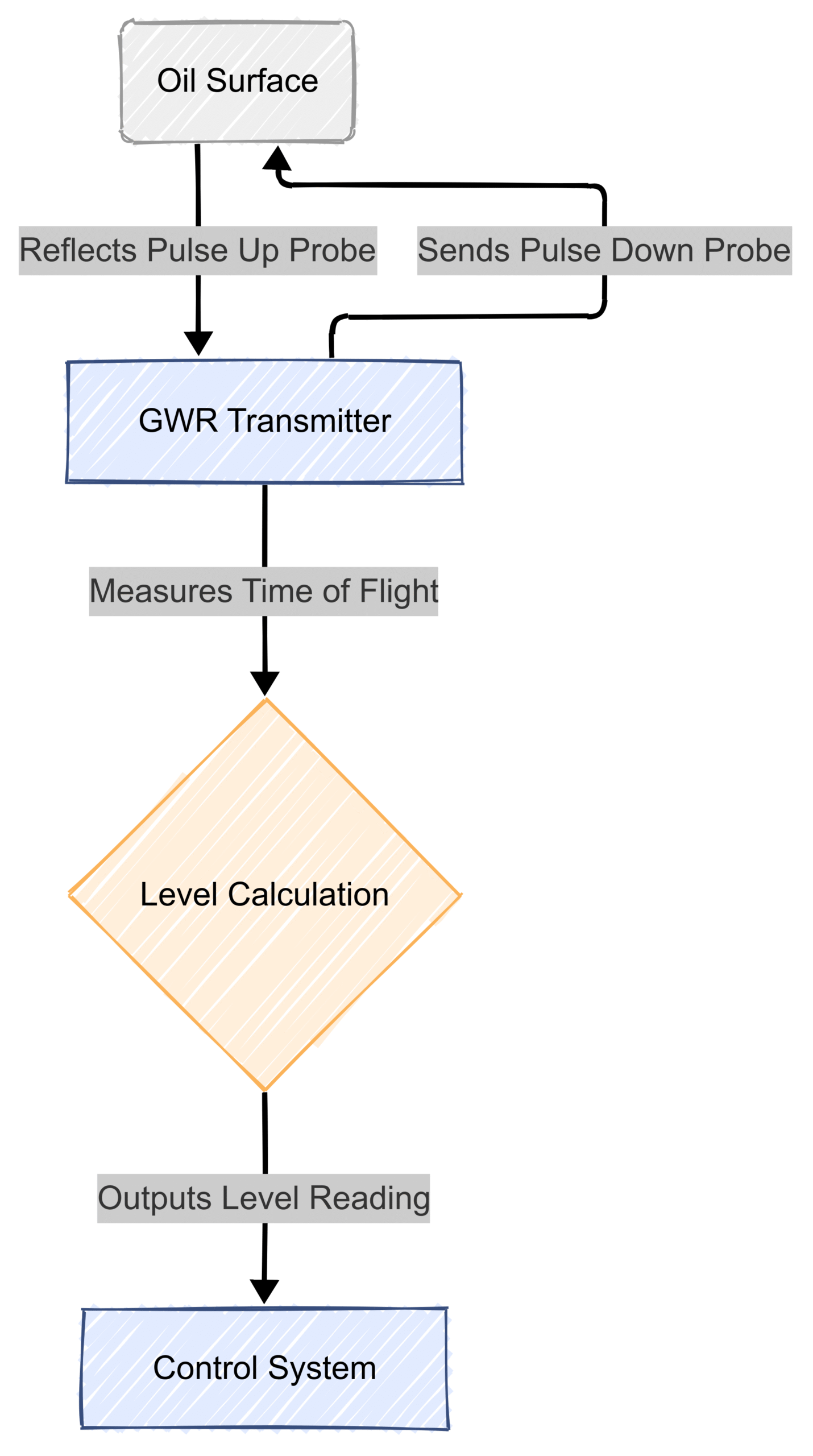
GWR transmitters also use microwave pulses, but instead of propagating through the air, the pulses are guided along a rigid or flexible probe that extends into the tank. When the pulse encounters the liquid surface, a portion of the energy is reflected back up the probe to the transmitter. The time of flight is measured to determine the liquid level. Because the signal is focused along the probe, it is less susceptible to interference from tank internals or foam.
Block Diagram of a Guided Wave Radar Level Transmitter:
Advantages:
Excellent Accuracy and Reliability: GWR provides highly accurate and repeatable measurements, even in challenging conditions.
Suitable for a Wide Range of Liquids: It can be used with various liquids, including those with low dielectric constants.
Unaffected by Foam and Vapors: The guided nature of the pulse makes it highly resistant to interference from foam, vapors, and turbulence.
Interface Measurement: GWR can also be used to measure the interface level between two immiscible liquids, such as oil and water.
Disadvantages:
Contact Measurement: The probe is in contact with the liquid, which can be a concern in highly corrosive or coating applications.
Probe Length Limitation: The length of the probe is limited, which can be a factor in very deep tanks.
Ideal Applications:
GWR is an excellent choice for applications requiring high accuracy, such as custody transfer measurement. It is also well-suited for tanks with internal obstructions, foam, or heavy vapors. Common applications include crude oil storage, separator vessels, and tanks where interface level detection is necessary.
3. Servo Tank Gauges
Servo tank gauges are a traditional yet highly accurate method for measuring liquid levels, often used for custody transfer applications where precision is paramount.
Working Principle
A servo gauge employs a small displacer suspended by a wire or tape from a drum in the gauge head. A servo motor, controlled by an electronic circuit, precisely positions the displacer so that it is partially submerged in the liquid. The electronics continuously measure the tension in the wire. When the liquid level changes, the buoyancy force on the displacer changes, causing a change in the wire tension. The servo motor then adjusts the position of the displacer to restore the original tension, and the amount of wire paid out or retracted directly corresponds to the change in liquid level.
Block Diagram of a Servo Tank Gauge:
Advantages:
Extremely High Accuracy: Servo gauges are among the most accurate level measurement devices available, making them ideal for custody transfer.
Direct Measurement: They provide a direct measurement of the liquid level, which is not inferred from other parameters.
Density and Interface Measurement: Advanced servo gauges can also measure liquid density and the interface level between oil and water.
Disadvantages:
Moving Parts: The presence of moving parts (motor, drum, wire) increases the potential for mechanical wear and requires more maintenance than non-contact technologies.
Slower Response Time: The mechanical nature of the system results in a slower response to rapid level changes compared to electronic instruments.
Ideal Applications:
Servo gauges are the gold standard for custody transfer applications in large bulk storage tanks for crude oil and refined products where high accuracy is a legal and financial requirement.
4. Hydrostatic Level Measurement
Hydrostatic level measurement is a simple, cost-effective, and reliable method based on the principle that the pressure exerted by a column of liquid is directly proportional to its height.
Working Principle
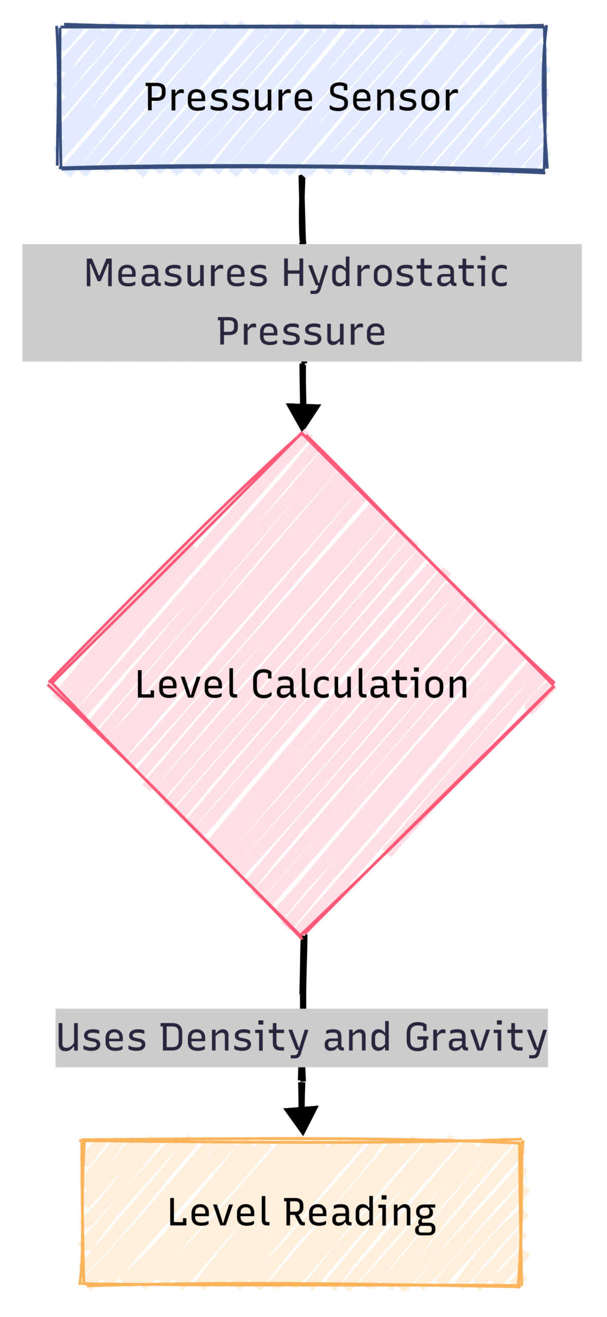
A pressure sensor is installed at or near the bottom of the tank. This sensor measures the hydrostatic pressure exerted by the liquid above it. Since the pressure is directly proportional to the height of the liquid column and its density (, where is pressure, is density, is the acceleration due to gravity, and is the height), the liquid level can be calculated. For accurate measurement, the density of the liquid must be known and relatively constant.
Block Diagram of a Hydrostatic Level Measurement System:
Advantages:
Cost-Effective: Hydrostatic sensors are generally less expensive than more sophisticated technologies like radar.
Simple and Robust: The technology is straightforward and the sensors are typically robust and durable.
Suitable for Various Tank Shapes: It can be used in tanks of different shapes and sizes.
Disadvantages:
Density Dependent: The accuracy of the measurement is directly affected by changes in the liquid’s density, which can vary with temperature.
Contact Measurement: The sensor is in contact with the process fluid, which can be a limitation for corrosive or aggressive liquids.
Pressure Variations: In pressurized tanks, a differential pressure measurement is required to compensate for the vapor pressure above the liquid.
Ideal Applications:
Hydrostatic level measurement is well-suited for applications where the liquid density is stable and high accuracy is not the primary concern. It is commonly used in water storage tanks, fuel oil day tanks, and some less critical chemical storage applications.
5. Ultrasonic Level Transmitters
Ultrasonic level transmitters are a non-contact technology that uses sound waves to measure the level of a liquid.
Working Principle
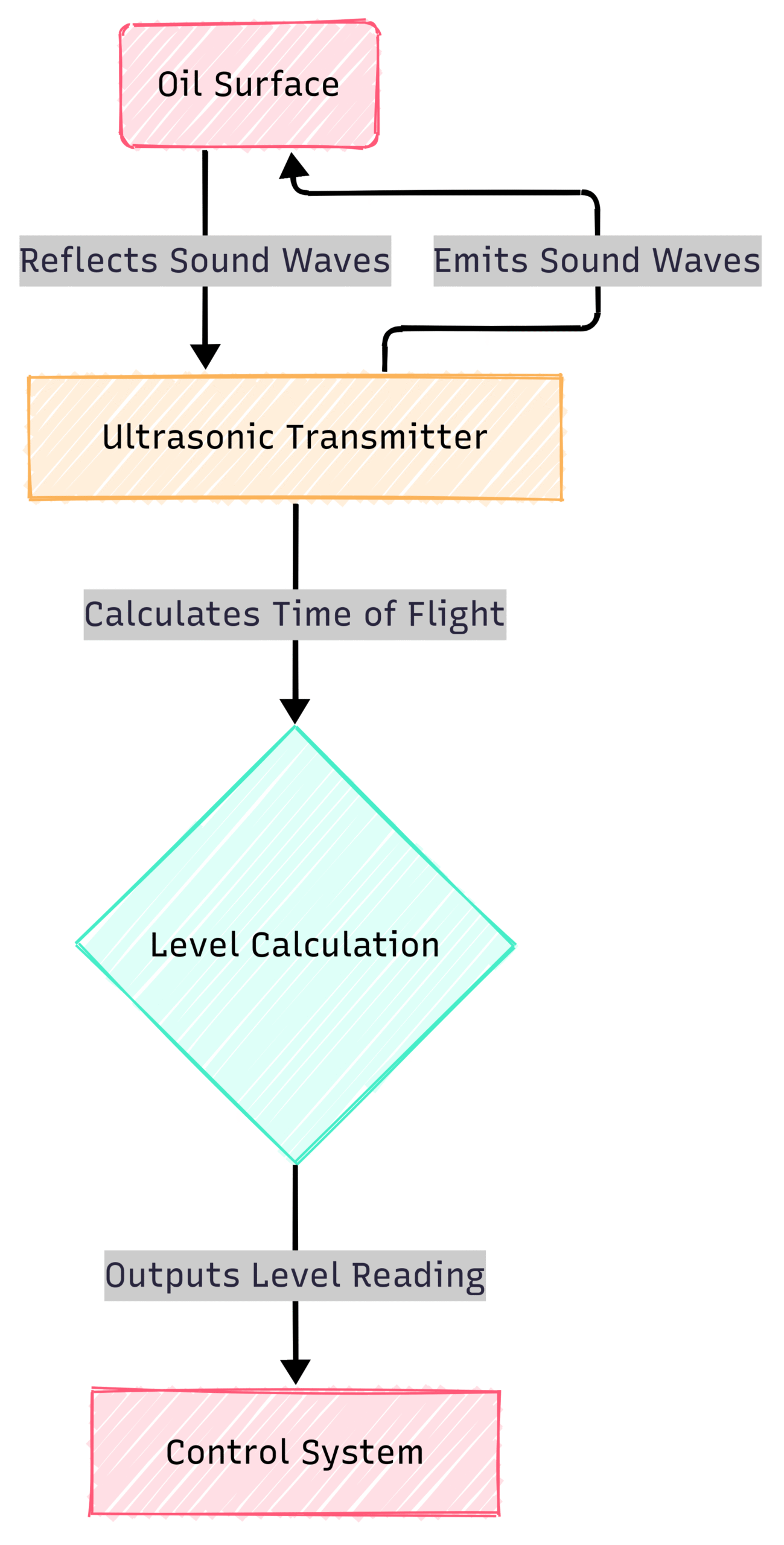
An ultrasonic transducer, mounted at the top of the tank, emits a burst of ultrasonic pulses. These pulses travel through the vapor space, reflect off the liquid surface, and return to the transducer. The transmitter measures the time of flight and calculates the distance to the liquid. Similar to radar, the liquid level is then determined by subtracting this distance from the total tank height.
Block Diagram of an Ultrasonic Level Transmitter:

Advantages:
Non-Contact Measurement: The sensor does not touch the process fluid, avoiding issues with corrosion and contamination.
Cost-Effective: Ultrasonic transmitters are often more affordable than radar systems.
Simple Installation: They are generally easy to install and commission.
Disadvantages:
Affected by Process Conditions: The speed of sound can be affected by changes in temperature, pressure, and the composition of the vapor space, which can impact accuracy.
Interference from Foam and Vapors: Foam, heavy vapors, and turbulence can absorb or scatter the ultrasonic signal, leading to erroneous readings.
Limited Range: The effective range of ultrasonic transmitters can be limited compared to radar.
Ideal Applications:
Ultrasonic level measurement is suitable for simple applications involving non-volatile, non-foaming liquids in atmospheric tanks. They are often used for monitoring water, diesel fuel, and some chemical storage tanks.
6. Magnetostrictive Level Transmitters
Magnetostrictive level transmitters are a highly accurate and reliable contact-based technology, often used in conjunction with magnetic level indicators.
Working Principle
A magnetostrictive transmitter consists of a waveguide (a long, thin rod) enclosed in a protective tube. A float containing a permanent magnet moves up and down the outside of this tube with the liquid level. The transmitter’s electronics send a current pulse down the waveguide. The magnetic field created by this pulse interacts with the magnetic field of the float. This interaction creates a tiny torsional twist in the waveguide, which travels back to the transmitter head as an ultrasonic wave. The time it takes for this wave to return is precisely measured to determine the position of the float and, therefore, the liquid level.
Block Diagram of a Magnetostrictive Level Transmitter:
[Transmitter Electronics] -> [Waveguide] --Current Pulse--> [Float with Magnet]
      ^                                                            |
      |___________________________Torsional Wave___________________|
Advantages:
High Accuracy and Resolution: Magnetostrictive technology provides very precise and repeatable measurements.
Unaffected by Liquid Properties: The measurement is not affected by changes in the liquid’s dielectric constant, conductivity, or density.
Interface Measurement: Like GWR, it can be used to measure the interface between two liquids.
Disadvantages:
Contact Measurement: The float is in contact with the process fluid.
Potential for Buildup: The float can be susceptible to buildup or sticking in dirty or viscous liquids.
Limited to Magnetic Floats: Requires a float with a magnet.
Ideal Applications:
Magnetostrictive transmitters are ideal for applications requiring high accuracy in clean liquids. They are commonly used in storage tanks for refined products, additives, and chemicals. They are also a popular choice for providing a continuous electronic output from a magnetic level indicator.
7. Magnetic Level Indicators (MLIs)
Magnetic level indicators are a simple, robust, and reliable way to visually indicate the level of a liquid in a tank. They are often used as a local visual indicator and can be combined with other technologies for remote monitoring.
Working Principle
An MLI consists of a chamber connected to the side of the tank, creating a bypass loop. Inside the chamber is a float containing a powerful magnet. As the liquid level in the tank rises and falls, the float moves up and down accordingly. On the outside of the chamber is an indicator with a series of bicolored, magnetically coupled flags or a follower. The magnetic field from the float causes these flags to flip, changing their color, or moves the follower, providing a clear visual representation of the liquid level.
Block Diagram of a Magnetic Level Indicator:
[Tank] <--> [Bypass Chamber with Magnetic Float] <--> [External Indicator (Flags/Follower)]
Advantages:
High Reliability and Safety: MLIs are inherently safe as they do not rely on power and the process fluid is contained within the chamber.
Clear Visual Indication: They provide a clear and easy-to-read local level indication.
Low Maintenance: With no electronic components, they require minimal maintenance.
Can be Combined with Transmitters: They can be fitted with magnetostrictive or guided wave radar transmitters to provide a continuous electronic output.
Disadvantages:
Local Indication Only (without transmitter): Without an added transmitter, they only provide a local visual indication.
Potential for Sticking: The float can potentially stick in dirty or crystallizing liquids.
Ideal Applications:
MLIs are widely used across the oil and gas industry for local level indication on a variety of tanks, including separators, accumulators, and storage tanks. They are a reliable backup to electronic level measurement systems.
8. Laser Level Transmitters
Laser level transmitters are a non-contact technology that uses a focused beam of light to measure the distance to a liquid surface.
Working Principle
A laser transmitter emits a short pulse of laser light, which is directed towards the liquid surface. The light reflects off the surface and returns to a highly sensitive detector in the transmitter. The time it takes for the laser pulse to travel to the surface and back is measured with extreme precision. This time of flight is then used to calculate the distance to the liquid level.
Block Diagram of a Laser Level Transmitter:
[Transmitter (Laser Emitter & Detector)] --Laser Pulse--> [Liquid Surface]
      ^                                                             |
      |___________________________Reflected Light____________________|
Advantages:
Very Narrow Beam: The laser beam is very narrow, allowing for precise targeting and measurement in tanks with internal obstructions or in narrow stilling wells.
High Accuracy: Laser transmitters can provide very accurate measurements.
Unaffected by Vapors: The measurement is generally not affected by the composition of the vapor space.
Disadvantages:
Susceptible to Optical Interference: The laser beam can be scattered or absorbed by heavy dust, steam, or foam, which can affect the measurement.
Surface Condition Dependent: The reflectivity of the liquid surface can impact performance.
Higher Cost: Laser transmitters can be more expensive than other non-contact technologies.
Ideal Applications:
Laser level transmitters are well-suited for applications requiring a very narrow beam to avoid internal tank obstructions. They are used for level measurement in tall, narrow tanks and for positioning applications. In the oil industry, they can be used for measuring the level of some refined products in specific tank configurations.
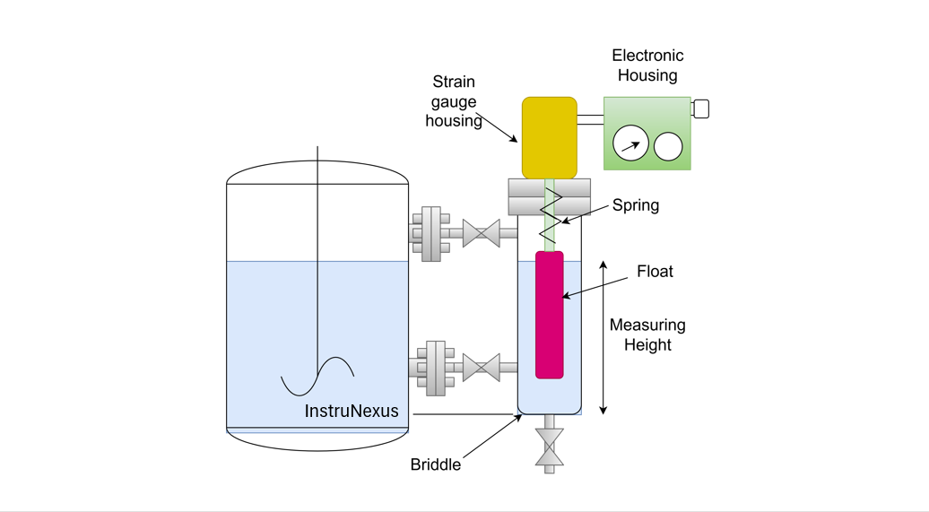
9. Displacer Level Transmitters
Displacer level transmitters are a well-established and reliable technology for measuring liquid level and interface.
Working Principle
A displacer, a cylindrical element with a known weight, is suspended in the liquid by a spring or torque tube. As the liquid level rises, the displacer is submerged, and the buoyant force acting on it increases. According to Archimedes’ principle, this buoyant force is equal to the weight of the liquid displaced. The increase in buoyant force reduces the apparent weight of the displacer, causing the spring to contract or the torque tube to twist. This movement is then converted into a proportional electrical signal representing the liquid level.
Block Diagram of a Displacer Level Transmitter:
Advantages:
Reliable and Proven Technology: Displacer transmitters have a long history of reliable performance in industrial applications.
Interface Measurement: They are very effective at measuring the interface level between two immiscible liquids.
Suitable for High Temperatures and Pressures: They can be designed to operate in high-temperature and high-pressure environments.
Disadvantages:
Moving Parts: The mechanical nature of the system means there are moving parts that can wear over time.
Density Dependent: The measurement is dependent on the density of the liquid.
Limited Span: The measuring range is limited by the length of the displacer.
Ideal Applications:
Displacer transmitters are commonly used in process vessels, separators, and storage tanks for both level and interface measurement. They are a good choice for applications with stable liquid densities and where a robust and reliable measurement is required.
10. Capacitance Level Transmitters
Capacitance level transmitters are a versatile and cost-effective technology that can be used for both continuous level measurement and point level detection.
Working Principle
A capacitance level transmitter uses a probe that acts as one plate of a capacitor, with the tank wall (if it is conductive) acting as the other plate. The liquid in the tank serves as the dielectric material between the plates. As the liquid level rises, the amount of dielectric material between the plates increases, which in turn increases the capacitance. The transmitter measures this change in capacitance and converts it into a level measurement. For non-conductive tanks, a concentric probe with an inner rod and outer tube is used.
Block Diagram of a Capacitance Level Transmitter:
[Probe (Capacitor Plate 1)] <--> [Liquid (Dielectric)] <--> [Tank Wall (Capacitor Plate 2)] -> [Transmitter] -> [Level Calculation]
Advantages:
Cost-Effective: Capacitance sensors are generally inexpensive.
Solid-State Design: They have no moving parts, resulting in low maintenance.
Versatile: They can be used with a wide variety of liquids, including conductive and non-conductive ones.
Disadvantages:
Dielectric Constant Dependent: The accuracy of the measurement is dependent on the dielectric constant of the liquid, which can change with temperature or composition.
Susceptible to Coating: Conductive coatings on the probe can cause erroneous readings.
Calibration Required: They often require calibration for the specific liquid being measured.
Ideal Applications:
Capacitance level transmitters are suitable for a range of applications in the oil and gas industry, particularly for monitoring the level of water, some chemicals, and interface detection between oil and water. They are a good choice for applications where the liquid properties are stable.
Comparative Summary of Level Measurement Technologies
Conclusion: Selecting the Right Technology for Your Needs
The selection of the optimal level measurement technology for an oil storage application is a critical decision that depends on a multitude of factors. There is no one-size-fits-all solution. A thorough understanding of the process conditions, the properties of the liquid being measured, the required accuracy, and the overall budget is essential for making an informed choice.
For applications demanding the highest accuracy, such as custody transfer, servo gauges and guided wave radar are often the preferred technologies. For general-purpose, non-contact level measurement in a wide variety of oil storage tanks, non-contact radar offers an excellent balance of accuracy, reliability, and low maintenance. In situations where cost is a primary driver and conditions are less challenging, hydrostatic and ultrasonic transmitters can be viable options. For robust local indication and as a reliable backup, the magnetic level indicator remains an industry staple.
Ultimately, by carefully considering the strengths and weaknesses of each technology, as outlined in this guide, and by partnering with experienced instrumentation suppliers, you can ensure the safe, efficient, and profitable operation of your oil storage facilities. The continuous evolution of these technologies promises even greater accuracy, reliability, and ease of use in the years to come, further solidifying their indispensable role in the global energy landscape.