
How Differential Pressure Level Transmitters Work in Oil Tanks: A Comprehensive Guide
In the vast and dynamic world of the oil and gas industry, accurate and reliable measurement of liquid levels in storage tanks is not just a matter of operational efficiency; it’s a critical safety imperative. Among the various technologies employed for this purpose, the differential pressure (DP) level transmitter stands out as a robust and time-tested solution. This comprehensive guide will delve deep into the working principles of differential pressure level transmitters, their application in oil tanks, and the nuances of their installation and calibration.
The Fundamental Principle: Hydrostatic Pressure
At its core, the operation of a differential pressure level transmitter is elegantly simple, relying on the fundamental principle of hydrostatic pressure. The pressure exerted by a column of liquid at a certain depth is directly proportional to the height of the liquid, its density (or specific gravity), and the gravitational force. This relationship is expressed by the formula:
P = ρgh
Where:
P is the hydrostatic pressure
ρ (rho) is the density of the liquid
g is the acceleration due to gravity
h is the height of the liquid column
By measuring the hydrostatic pressure at the bottom of a tank, a DP transmitter can accurately infer the liquid level. However, the application of this principle varies depending on whether the tank is open to the atmosphere or is a closed, pressurized vessel.
Measuring Level in Open (Vented) Oil Tanks
An open, or vented, tank is one that is open to the atmosphere. In such a scenario, the pressure at the surface of the liquid is the atmospheric pressure. To measure the level in an open tank, a single pressure transmitter can be used, but a differential pressure transmitter offers a more stable and accurate reading by compensating for atmospheric pressure fluctuations.
The high-pressure (HP) port of the DP transmitter is connected to the bottom of the tank. The low-pressure (LP) port is left open to the atmosphere. The transmitter then measures the difference between the pressure at the bottom of the tank (hydrostatic pressure + atmospheric pressure) and the atmospheric pressure. This effectively isolates the hydrostatic pressure, which is directly proportional to the liquid level.
Calculation for an Open Tank:
P_high = P_hydrostatic + P_atmospheric
P_low = P_atmospheric
ΔP = P_high – P_low = P_hydrostatic
The transmitter is calibrated so that a zero differential pressure corresponds to an empty tank (0% level) and the maximum expected differential pressure corresponds to a full tank (100% level).

Tackling the Challenge of Closed (Pressurized) Oil Tanks
In the oil and gas industry, many tanks are closed and operate under a blanket of gas pressure, which can be variable. This vapor pressure on the surface of the liquid would introduce a significant error if a simple pressure transmitter were used. This is where the “differential” aspect of the DP transmitter becomes indispensable.
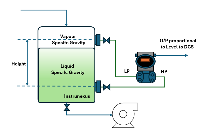
In a closed tank, the HP port of the transmitter is again connected to the bottom of the tank. However, the LP port is now connected to the vapor space at the top of the tank. This setup allows the transmitter to measure the difference between the total pressure at the bottom (hydrostatic pressure + gas pressure) and the gas pressure at the top. The gas pressure is thus canceled out, leaving only the hydrostatic pressure of the liquid.
Calculation for a Closed Tank:
P_high = P_hydrostatic + P_gas
P_low = P_gas
ΔP = P_high – P_low = P_hydrostatic
This method ensures that fluctuations in the tank’s blanket pressure do not affect the level measurement.
Dry Leg vs. Wet Leg Installations
The connection from the LP port to the top of the tank can be configured in two ways: a “dry leg” or a “wet leg” installation.
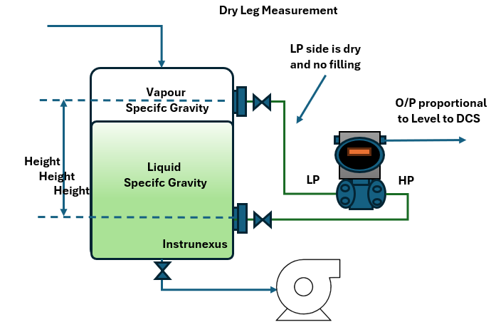
1. Dry Leg Installation:
A dry leg installation is used when the vapor in the tank is non-condensing. The impulse piping connecting the LP port to the top of the tank is filled with this non-condensing gas. This is a straightforward and common setup.
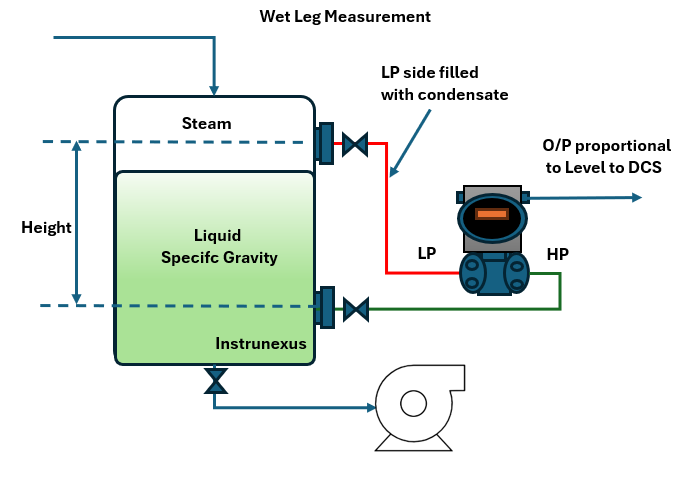
2. Wet Leg Installation:
A wet leg installation is necessary when the vapor in the tank is likely to condense. If the impulse line were to fill with condensate, it would create a variable hydrostatic pressure on the LP side of the transmitter, leading to inaccurate readings. To prevent this, the impulse line is intentionally filled with a stable, non-volatile liquid (often the same as the process liquid or a compatible one).
In this configuration, the hydrostatic pressure of the liquid in the wet leg must be compensated for in the transmitter’s calibration. The transmitter will always see a pressure on the low side, even when the tank is empty. This results in a “suppressed zero” calibration.
Calculation for a Wet Leg Installation:
The differential pressure measured by the transmitter will be the difference between the pressure at the HP port and the pressure at the LP port, which now includes the hydrostatic pressure of the wet leg.
P_high = P_hydrostatic_tank + P_gas
P_low = P_hydrostatic_wet_leg + P_gas
ΔP = (P_hydrostatic_tank + P_gas) – (P_hydrostatic_wet_leg + P_gas) = P_hydrostatic_tank – P_hydrostatic_wet_leg
Key Components of a Differential Pressure Level Measurement System
A typical DP level transmitter system consists of several key components:
The DP Transmitter: This is the heart of the system. It houses the sensing element (typically a diaphragm) that deflects in response to the pressure difference. This deflection is then converted into an electrical signal (commonly a 4-20 mA analog signal or a digital signal with HART, Foundation Fieldbus, or Profibus communication).
Impulse Piping: These are the tubes that connect the high and low-pressure ports of the transmitter to the process tappings on the tank. The proper installation and maintenance of impulse lines are crucial for accurate measurements.
Isolation Valves and Manifolds: These valves allow for the isolation of the transmitter from the process for maintenance, calibration, or replacement without shutting down the entire process. A manifold is a combination of valves in a single block that simplifies this process.
Process Connections (Tappings): These are the points on the tank where the impulse lines are connected. Their location is critical for obtaining an accurate representation of the liquid level.
Challenges and Considerations in Oil Tank Level Measurement
While DP transmitters are highly reliable, several factors can affect their accuracy in oil tank applications:

Changes in Fluid Density: The calculation of level from hydrostatic pressure is directly dependent on the density of the liquid. In the oil industry, the density of crude oil and its derivatives can vary significantly with temperature and composition. This is a major source of potential error.
Solution: For applications where density changes are significant, a multivariable transmitter that can also measure temperature can be used to compensate for density variations. Alternatively, a separate density measurement can be incorporated into the control system to correct the level reading.
Temperature Effects on Impulse Lines: In wet leg installations, temperature fluctuations can cause the density of the fill fluid in the impulse lines to change, leading to measurement errors.
Solution: Using insulated or heat-traced impulse lines can help maintain a stable temperature. Alternatively, electronic remote sensors can be used to eliminate the need for long impulse lines.
Clogging of Impulse Lines: The viscous nature of some crude oils and the presence of sediments can lead to the clogging of impulse lines, resulting in erroneous readings.
Solution: Proper design of the impulse lines with adequate sloping and the use of diaphragm seals can prevent clogging. Regular maintenance and flushing of the lines are also essential.
Interface Level Measurement: In applications such as separators, it is often necessary to measure the interface level between two immiscible liquids, such as oil and water.
Solution: DP transmitters can be used for interface level measurement, but the calculation is more complex as it involves the densities of both liquids. The transmitter measures the total hydrostatic pressure, and with known densities, the interface level can be calculated.
Installation and Calibration: The Keys to Accuracy
The adage “a measurement is only as good as its calibration” holds particularly true for DP level transmitters. Proper installation and meticulous calibration are paramount for achieving accurate and reliable level measurements.
Installation Best Practices:
Transmitter Location: The transmitter should be located as close to the tank as possible to minimize the length of the impulse lines. It should be easily accessible for maintenance and calibration.
Impulse Line Sloping: For gas service (dry leg), the impulse lines should be sloped downwards from the process connection to the transmitter to allow any condensate to drain back into the process. For liquid service, the lines should be sloped upwards from the process connection to the transmitter to allow any trapped gas to vent back to the process.
Process Tapping Points: The high-pressure tapping should be as close to the bottom of the tank as possible to maximize the measurement range. The low-pressure tapping for closed tanks should be in the vapor space, well above the maximum liquid level.
Calibration Procedure:
Calibration involves establishing a relationship between the differential pressure input and the desired output signal (e.g., 4-20 mA). The general steps include:
Isolation: Isolate the transmitter from the process using the isolation valves.
Zero and Span Adjustment:
Zero Adjustment: With the tank empty (or at the 0% level), the corresponding differential pressure is applied to the transmitter, and the output is adjusted to 4 mA.
Span Adjustment: With the tank full (or at the 100% level), the corresponding differential pressure is applied, and the output is adjusted to 20 mA.
Verification: The calibration is verified by applying several known pressure points within the calibrated range and checking the corresponding output.
Modern “smart” transmitters with digital communication protocols simplify the calibration process, allowing for remote calibration and diagnostics.
The Enduring Value of Differential Pressure Level Measurement
In an era of increasingly sophisticated level measurement technologies, such as radar and ultrasonic transmitters, the differential pressure level transmitter continues to be a cornerstone of the oil and gas industry. Its enduring popularity stems from its:
Reliability and Robustness: DP transmitters are known for their long service life and ability to withstand harsh industrial environments.
Versatility: They can be used for a wide range of liquids, temperatures, and pressures.
Cost-Effectiveness: Compared to some other technologies, DP transmitters offer a cost-effective solution for many level measurement applications.
Proven Track Record: With decades of successful application, the technology is well-understood and trusted by engineers and technicians worldwide.
Conclusion: A Vital Tool for a Vital Industry
The seemingly simple principle of hydrostatic pressure, when harnessed by a differential pressure level transmitter, provides a powerful and reliable method for monitoring the levels in oil tanks. From the vast storage farms of crude oil to the intricate processes within a refinery, the accurate and continuous measurement of liquid levels is fundamental to safe and efficient operations. By understanding the working principles, the nuances of installation and calibration, and the potential challenges, engineers and operators can ensure that these workhorse instruments continue to play their vital role in the ever-evolving landscape of the oil and gas industry. The ability to accurately know “how much is in the tank” is a critical piece of the puzzle, and the differential pressure level transmitter remains a key to solving it.