
Installing DP Level Transmitters: A Comprehensive Step-by-Step Guide for Engineers
In the realm of industrial instrumentation and process control, the accurate measurement of liquid level is paramount for safe and efficient operations. Among the various technologies available, the differential pressure (DP) level transmitter remains a robust, reliable, and widely used solution. For any engineer involved in plant maintenance, project execution, or process optimization, a thorough understanding of how to correctly install these instruments is a critical skill.
This comprehensive guide will walk you through the entire installation process of a DP level transmitter, from pre-installation checks to final commissioning. We’ll delve into the nuances of mounting, impulse piping configurations, and the essential steps to ensure your measurements are accurate and repeatable.
Understanding the DP Level Measurement Principle
Before we dive into the installation specifics, let’s briefly revisit the fundamental principle behind DP level measurement. The technique relies on Pascal’s principle, which states that the pressure exerted by a fluid at a certain depth is proportional to its height (or level) and its specific gravity.
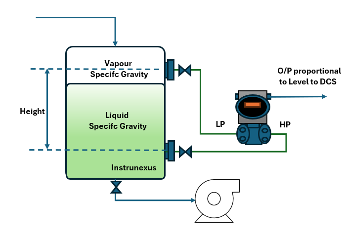
A DP transmitter measures the pressure difference between two points. In a typical level application, the high-pressure (HP) side of the transmitter is connected to the bottom of the vessel, and the low-pressure (LP) side is connected to the top. The measured differential pressure is then directly proportional to the liquid level.
For open tanks, the LP side is vented to the atmosphere. For closed or pressurized tanks, the LP side is connected to the vapor space at the top of the tank to compensate for the tank pressure.
Pre-Installation Checks: Laying the Groundwork for Success
A successful installation begins long before the first wrench is turned. Thorough pre-installation checks will save you time, prevent costly errors, and ensure the safety of your personnel and equipment.
1. Verify the Bill of Materials (BOM)
Transmitter: Confirm that the received DP transmitter model matches the specifications in your project documentation. Check the material of construction, pressure rating, and any special features like diaphragm seals.
Manifold: Ensure you have the correct type of manifold (2-valve, 3-valve, or 5-valve) with the appropriate pressure rating and material.
Impulse Piping and Fittings: Verify that all tubing, pipes, and fittings are of the correct size, material, and pressure rating for the application.
Mounting Bracket: Check if the supplied mounting bracket is suitable for the intended installation location (e.g., pipe mount or surface mount).
Gaskets and Seals: Ensure you have the correct gaskets and sealing materials compatible with the process fluid and operating conditions.
2. Inspect the Installation Location
Accessibility: The transmitter should be installed in a location that is easily and safely accessible for maintenance and calibration.
Vibration and Temperature: Avoid installing the transmitter in areas with excessive vibration or extreme temperatures, as these can affect its accuracy and longevity.
Clearances: Ensure there is sufficient clearance around the transmitter for impulse line routing, manifold operation, and removal for servicing.
3. Review Process Conditions
Fluid Properties: Understand the properties of the process fluid, including its specific gravity, corrosiveness, and tendency to foul or crystallize. This will influence the choice of materials and the need for features like diaphragm seals or heat tracing.
Operating Pressure and Temperature: Confirm that the selected transmitter and associated components can safely withstand the maximum operating pressure and temperature of the process.
Mounting the DP Level Transmitter: A Secure Foundation
The physical mounting of the transmitter is a critical step that impacts its stability and the accuracy of its readings.
Mounting Options
Pipe Mounting: This is a common method where the transmitter is secured to a vertical or horizontal pipe using a U-bolt type bracket.
Surface Mounting: The transmitter is mounted directly to a flat surface, such as a wall or a structural support.
Mounting Best Practices
Orientation: For most applications, the transmitter should be mounted vertically with the pressure connections pointing downwards. This helps to prevent the accumulation of sediment or gas bubbles in the sensing diaphragms.
Stability: Ensure the mounting is firm and free from vibration. Use lock washers or thread-locking compound on the mounting bolts to prevent loosening over time.
Leveling: The transmitter should be mounted as level as possible to minimize any potential zero shift.
Impulse Piping Installation: The Arteries of Measurement
The impulse piping connects the process vessel to the DP transmitter and is arguably the most critical part of the installation. Improperly routed or installed impulse lines are a primary source of measurement errors.
General Guidelines for Impulse Piping
Slope: Impulse lines should be sloped continuously to allow for the venting of gases in liquid service or the draining of liquids in gas service. A minimum slope of 1:12 (1 inch of fall for every 12 inches of horizontal run) is recommended.
Length: Keep the impulse lines as short as possible to minimize response time and potential temperature effects. The lengths of the high-pressure and low-pressure impulse lines should be as equal as possible.
Bends: Avoid sharp bends in the tubing. Use a tube bender to create smooth, gradual bends.
Support: Properly support the impulse tubing to prevent sagging and vibration.
Impulse Piping Configurations for Different Applications
The correct configuration of the impulse piping depends on the type of tank (open or closed) and the nature of the process fluid.
Open Tank Level Measurement
In an open tank, the liquid is at atmospheric pressure. The HP side of the transmitter connects to the bottom of the tank, and the LP side is vented to the atmosphere.

Closed (Pressurized) Tank Level Measurement
For a closed tank, the LP side of the transmitter is connected to the vapor space at the top of the tank to compensate for the tank pressure.
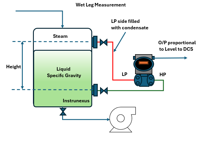
Wet Leg vs. Dry Leg Configurations
When measuring the level of a condensing fluid (like steam) in a closed tank, a “wet leg” configuration is used. In this setup, the LP impulse line is intentionally filled with a stable liquid (often the condensate itself) to provide a constant reference pressure.
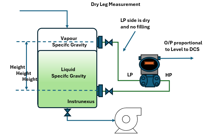
In a “dry leg” configuration, used for non-condensing gases, the LP impulse line is kept free of liquid.
Diaphragm Seals: Isolating the Transmitter
For corrosive, viscous, or high-temperature fluids, diaphragm seals are used to isolate the transmitter from the process. The pressure is transmitted through a fill fluid within a capillary tube.
Diaphragm Seal Installation Considerations
Capillary Length: Keep capillary tubes as short as possible to minimize temperature-induced errors.
Capillary Routing: Protect the capillary tubing from physical damage and extreme temperatures. Avoid sharp bends.
Elevation: The transmitter should ideally be mounted at the same elevation as the lower diaphragm seal. If there is a significant elevation difference, this must be accounted for during calibration.
Manifold Installation and Operation: The Control Center
The manifold is a critical component that allows for the isolation, equalization, and venting of the transmitter for maintenance and calibration without shutting down the process.
Types of Manifolds
2-Valve Manifold: Provides isolation and venting.
3-Valve Manifold: The most common type, with two block valves (for the HP and LP sides) and one equalizing valve.
5-Valve Manifold: Includes two additional vent/test valves for in-situ calibration.
Manifold Operation Sequence (for a 3-Valve Manifold)
Placing the Transmitter in Service:
Ensure all valves are closed.
Slowly open the equalizing valve. This ensures both sides of the transmitter are at the same pressure, preventing a sudden pressure shock.
Slowly open the high-pressure block valve.
Close the equalizing valve.
Slowly open the low-pressure block valve.
Taking the Transmitter out of Service:
Close the low-pressure block valve.
Open the equalizing valve.
Close the high-pressure block valve.
Vent the transmitter body if necessary.
Commissioning the DP Level Transmitter: Bringing it to Life
Commissioning is the final and most crucial phase of the installation process. It involves configuring the transmitter and verifying its accurate operation.
1. Electrical Wiring
Power Supply: Ensure the transmitter is connected to a stable power supply with the correct voltage and polarity.
Signal Wiring: Use shielded twisted-pair cable for the 4-20mA signal to minimize electrical noise interference. Ground the shield at one end only, typically at the control system side.
Conduit Seals: Use appropriate conduit seals to prevent moisture ingress into the transmitter housing, especially in outdoor or hazardous area installations.
2. Configuration and Calibration
HART Communicator: Use a Handheld HART (Highway Addressable Remote Transducer) Communicator or a similar device to configure the transmitter.
Range Setting: Set the Lower Range Value (LRV) and Upper Range Value (URV) based on the calculated differential pressure at 0% and 100% level. The formula for calculating the differential pressure is:
Where:
is the differential pressure
is the height of the liquid
is the specific gravity of the liquid
Zero and Span Adjustment: Perform a zero and span adjustment to ensure the transmitter’s output corresponds accurately to the minimum and maximum levels.
Zero Adjustment (LRV): With the tank at its minimum level (or simulating this condition through the manifold), adjust the transmitter output to 4mA.
Span Adjustment (URV): With the tank at its maximum level (or a known higher level), adjust the transmitter output to 20mA.
3. Leak Testing
Once the transmitter is in service, meticulously check all connections for leaks, including the process taps, manifold, and impulse line fittings. Use a suitable leak detection solution.
4. Final Verification
Compare with Manual Gauging: Compare the level reading from the newly installed transmitter with a manual measurement (e.g., from a sight glass or by dipping the tank) to verify its accuracy.
Documentation: Record all installation details, including the transmitter tag number, location, calibration settings, and any deviations from the original design. This information is invaluable for future maintenance and troubleshooting.
Common Pitfalls and Troubleshooting
Even with the best planning, issues can arise. Here are some common problems and their likely causes:
Conclusion: A Commitment to Precision
Installing a DP level transmitter is more than just a mechanical task; it’s a meticulous engineering process that demands attention to detail at every stage. By following the steps outlined in this guide – from diligent pre-installation checks to thorough commissioning – you can ensure that your level measurement system is not only reliable and accurate but also safe and easy to maintain. A properly installed DP level transmitter will provide years of trouble-free service, contributing significantly to the overall efficiency and safety of your plant operations. Remember, the quality of your measurement is a direct reflection of the quality of your installation.