
Common Installation Mistakes with Radar Level Instruments
In the world of industrial process control, accurate and reliable level measurement is paramount. Radar level transmitters have become a go-to technology for a wide variety of applications, offering high accuracy, low maintenance, and the ability to measure a diverse range of liquids and solids. However, even the most sophisticated instrument will fail to deliver optimal performance if not installed correctly. Improper installation is a leading cause of measurement errors, leading to process inefficiencies, safety hazards, and costly downtime.
This comprehensive guide will walk you through the most common installation mistakes with radar level instruments, providing you with the knowledge to avoid these pitfalls and ensure your measurements are always on target. We’ll explore everything from incorrect mounting locations to the often-overlooked impact of the surrounding environment.
1. Improper Mounting Location: The Foundation of Inaccuracy
Perhaps the most fundamental and frequent mistake is choosing the wrong location to mount the radar level transmitter. The ideal position is not a matter of convenience but a critical factor in obtaining a clear and strong signal.
The Problem
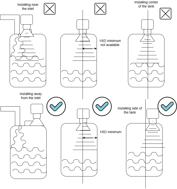
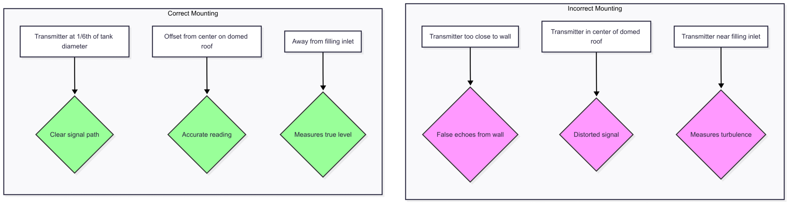
Placing the transmitter too close to the tank wall, directly in the center of a domed or conical roof, or near the filling curtain or other process inlets can introduce a multitude of issues.
Wall Interference: When mounted too close to the tank wall, the radar’s microwave signal can reflect off the vertical surface, creating false echoes that the instrument may misinterpret as the actual level. This is particularly problematic in tanks with rough or coated walls.
Central Mounting on Domed Roofs: Installing a radar transmitter in the center of a domed or conical roof can create a “double echo” effect. The curved surface can act as a parabolic reflector, focusing the returning signal and causing a distorted reading.
Proximity to Inlets: Placing the transmitter directly in the path of the filling stream or near other inlets will lead to erroneous measurements due to the turbulence and splashing created by the incoming material. The instrument will measure the agitated surface rather than the true level.
The Solution: Strategic Positioning is Key
To avoid these issues, follow these guidelines for optimal transmitter placement:
The 1/6th Rule: As a general rule of thumb, install the radar transmitter at approximately one-sixth of the tank’s diameter away from the side wall. This positioning minimizes the risk of wall interference while still providing a clear view of the material surface.
Avoid the Center: Never mount the transmitter in the geometric center of the tank, especially on curved or sloped roofs.
Clear of Obstructions: Ensure the signal path is free from any obstructions, including agitators, support beams, and, as mentioned, filling streams.
Here’s a visual representation of correct and incorrect mounting locations:
2. Nozzle Nightmares: When the Connection Causes Chaos
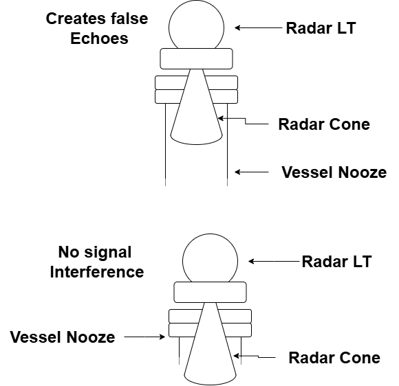
The nozzle, the very point of connection for the radar transmitter, can be a significant source of measurement problems if not handled correctly. Long, narrow nozzles can act as a waveguide, creating unwanted reflections and interfering with the primary signal.
The Problem
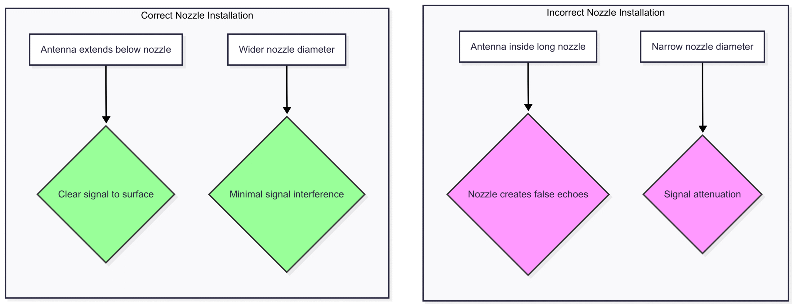
Nozzle Echoes: A long nozzle can create its own set of reflections that can be stronger than the actual level echo, leading the instrument to report a fixed, incorrect high level. This is especially true for nozzles with a small diameter.
Signal Attenuation: The nozzle can also attenuate or weaken the radar signal, particularly for instruments with a wider beam angle.
The Solution: Mind the Nozzle
Short and Wide is Better: Whenever possible, use a short nozzle with a larger diameter. This minimizes the “waveguide” effect and allows for a clearer signal path.
Antenna Extension: If a long nozzle is unavoidable, ensure the antenna of the radar transmitter extends sufficiently below the end of the nozzle. The general recommendation is that the antenna should protrude at least 10mm (0.4 inches) below the nozzle opening.
Proper Nozzle Design: For new installations, consider using angled nozzles or nozzles with a chamfered edge to deflect false echoes away from the antenna.
This diagram illustrates the importance of proper antenna placement relative to the nozzle:
3. Ignoring Internal Obstructions: The Unseen Enemy
Tanks are rarely empty vessels. They often contain a variety of internal structures such as agitators, heating coils, support beams, and ladders. Ignoring these obstructions during installation is a recipe for measurement disaster.
The Problem
Any object in the radar’s line of sight can create a reflection, generating a false echo that can be mistaken for the actual material level. The instrument will see the obstruction, not the surface you want to measure.
The Solution: Map and Avoid
Know Your Tank: Before installation, thoroughly inspect the tank’s interior and create a diagram of all internal structures.
Strategic Aiming: Position the radar transmitter so that its beam path is completely clear of any obstructions. This may require careful consideration of the beam angle of the specific radar model.
False Echo Suppression: Most modern radar level transmitters have a “false echo suppression” or “mapping” feature. This allows you to “teach” the instrument to ignore the static echoes from internal structures. This is typically done when the tank is empty.
Stilling Wells: In cases with extreme turbulence or numerous internal obstructions, a stilling well can be an effective solution. A stilling well is a vertical pipe installed in the tank that provides a calm, clear path for the radar signal. However, the stilling well itself must be installed correctly, ensuring it is perfectly vertical and has ventilation holes to allow the level inside the well to equalize with the level in the tank.
4. Antenna Contamination: A Dirty Lens Distorts the View
The antenna of the radar level transmitter is its “eye.” If this “eye” becomes coated with material, its ability to send and receive signals will be impaired, leading to inaccurate or lost readings.
The Problem
Buildup: In applications with sticky, viscous, or dusty materials, buildup on the antenna is a common problem. This coating can absorb or scatter the radar signal.
Condensation: In humid environments or applications with significant temperature variations, condensation can form on the antenna, which can also interfere with the signal.
The Solution: Keep it Clean
Self-Cleaning Antennas: Many manufacturers offer antennas with non-stick coatings (like PTFE) or designs that are less prone to buildup.
Air Purge: For particularly challenging applications, an air purge system can be installed to periodically blast the antenna with compressed air, keeping it clean.
Strategic Placement: Installing the transmitter in a location where it is less likely to be splashed or exposed to heavy dust can also help to minimize contamination.
Regular Maintenance: In some cases, periodic manual cleaning of the antenna may be necessary. Always follow the manufacturer’s instructions for cleaning to avoid damaging the antenna.
5. Overlooking Process Conditions: The Environmental Factor
The environment inside the tank can have a significant impact on the performance of a radar level transmitter. Factors like foam, turbulence, and dust can all interfere with the radar signal.
The Problem
Foam: Many processes generate foam on the surface of the liquid. Some types of foam can absorb the radar signal, while others can create a strong reflection, leading the instrument to measure the top of the foam layer instead of the actual liquid level.
Turbulence: A highly agitated or turbulent surface can scatter the radar signal, resulting in a weak or unstable reading.
Heavy Dust: In solid applications, heavy dust in the atmosphere can also attenuate the radar signal, making it difficult to obtain a reliable measurement.
The Solution: Adapt and Conquer
Choose the Right Frequency: Higher frequency radar transmitters (around 80 GHz) have a narrower beam angle and are generally better at penetrating foam and dust. Lower frequency radars (around 6 to 26 GHz) may be more suitable for applications with heavy condensation.
Advanced Signal Processing: Modern radar instruments often feature advanced signal processing algorithms that can help to filter out the effects of foam and turbulence.
Stilling Wells: As mentioned earlier, stilling wells are an excellent solution for overcoming issues with foam and turbulence.
6. Improper Electrical Installation and Grounding: The Silent Saboteur
A flawless mechanical installation can be completely undermined by poor electrical work. Issues with power supply, grounding, and wiring can lead to a host of problems, from intermittent readings to complete instrument failure.
The Problem
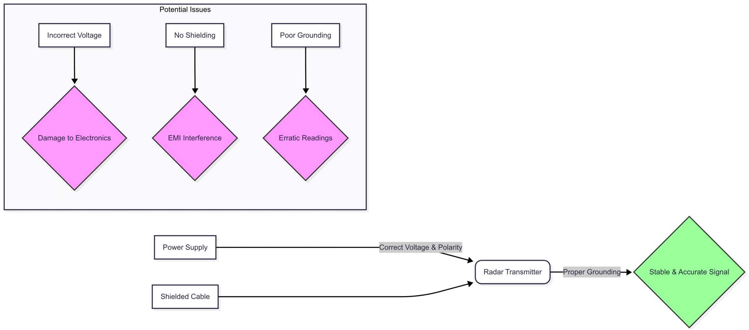
Incorrect Voltage: Supplying the wrong voltage to the transmitter can damage the electronics.
Poor Grounding: Improper grounding can make the instrument susceptible to electrical noise and interference, leading to erratic readings.
Incorrect Wiring: Reversed polarity or loose connections will prevent the instrument from functioning correctly.
The Solution: Follow the Manual
Read the Instructions: Always consult the manufacturer’s installation manual for the correct wiring diagrams and power supply requirements.
Ensure a Solid Ground: Provide a dedicated, low-impedance ground connection for the transmitter.
Use Shielded Cable: In electrically noisy environments, use shielded twisted-pair cable for the signal wiring to protect against electromagnetic interference (EMI).
A simplified view of proper electrical connection:
Conclusion: A Foundation for Success
The accuracy and reliability of your radar level measurement system are directly tied to the quality of its installation. By understanding and actively avoiding these common pitfalls, you can ensure that your instruments perform to their full potential, providing you with the precise and dependable data you need to optimize your processes, enhance safety, and reduce operational costs.
Remember, a successful installation is not an accident. It is the result of careful planning, a thorough understanding of the application, and a commitment to following best practices. Take the time to get it right from the start, and your radar level instruments will reward you with years of trouble-free operation.