
Troubleshooting Radar Level Transmitters in Process Plants: A Comprehensive Guide 🧜♀️
Introduction
Radar level transmitters are essential instruments in modern process plants, providing accurate and reliable level measurements for a wide range of liquids and solids. Their non-contact nature offers significant advantages, especially in harsh environments or with corrosive materials. However, like any sophisticated technology, radar level transmitters can experience issues that require systematic troubleshooting. This comprehensive guide will delve into common problems encountered with radar level transmitters in process plants and provide step-by-step approaches to diagnose and resolve them.
Understanding the Basics of Radar Level Transmitters
Before diving into troubleshooting, it’s crucial to understand the fundamental principles of how radar level transmitters work. These devices emit electromagnetic waves, typically in the microwave frequency range, towards the surface of the material being measured. The waves reflect off the surface, and the transmitter receives the reflected signal. By measuring the time it takes for the signal to travel to the surface and back, the transmitter can accurately calculate the distance to the material level. This distance, combined with the known height of the tank or vessel, allows for the determination of the level.
There are two main types of radar level transmitters:
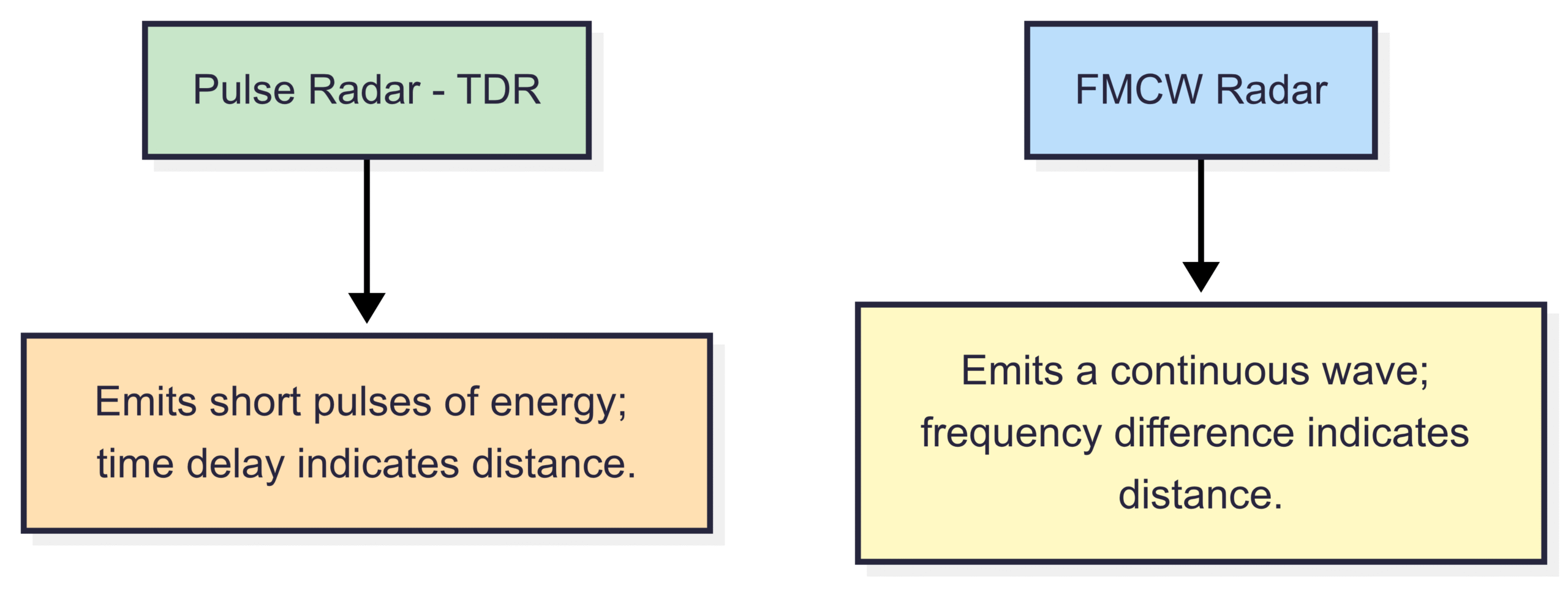
Pulse Radar (Time Domain Reflectometry – TDR): These transmitters emit short pulses of electromagnetic energy. The time delay between the emitted pulse and the received echo is directly proportional to the distance to the surface.
Frequency Modulated Continuous Wave (FMCW) Radar: These transmitters emit a continuous wave with a linearly changing frequency. The difference in frequency between the emitted and received signals is proportional to the distance to the surface.
Both types offer high accuracy and reliability but may be susceptible to different types of interference and operational challenges.
Common Problems and Troubleshooting Steps
When a radar level transmitter malfunctions or provides inaccurate readings, a systematic approach to troubleshooting is essential. Here’s a breakdown of common problems and corresponding troubleshooting steps:
1. No Signal or Intermittent Signal
Possible Causes:
Power Supply Issues: The transmitter may not be receiving adequate power.
Wiring Problems: Loose, corroded, or incorrectly wired connections can disrupt the signal.
Antenna Obstruction or Damage: Buildup on the antenna, physical damage, or incorrect antenna type can impede signal transmission and reception.
Internal Transmitter Failure: Although less common, internal electronic components can fail.
Signal Absorption: Highly absorptive media can weaken the reflected signal below the receiver’s sensitivity.
Troubleshooting Steps:

Verify Power Supply: Check the power source to the transmitter, ensuring the voltage and current are within the specified limits. Inspect power cables for damage or loose connections.
Inspect Wiring: Carefully examine all wiring connections to the transmitter, including power, signal, and grounding. Ensure terminals are clean, tight, and correctly wired according to the manufacturer’s documentation.
Check Antenna: Visually inspect the antenna for any physical damage, such as cracks or bends. If possible, safely access the antenna and check for any buildup of process material, condensation, or foreign objects. Clean the antenna carefully if necessary, following the manufacturer’s recommendations. Ensure the antenna type is appropriate for the application.
Review Transmitter Configuration: Verify that the transmitter is configured correctly for the application, including the tank dimensions, dielectric constant of the material (if applicable), and output signal parameters.
Signal Strength Diagnostics: Many modern radar level transmitters have built-in diagnostic tools that can indicate signal strength. Check the transmitter’s display or interface for these readings. Low signal strength could indicate antenna issues, signal absorption, or incorrect mounting.
Loop Check: If the transmitter is part of a 4-20 mA current loop, perform a loop check to verify the integrity of the wiring and the functionality of the receiving device (e.g., PLC, DCS).
Consider Process Conditions: Investigate if any changes in the process material (e.g., significant changes in dielectric constant, excessive foaming, heavy turbulence) could be affecting signal reflection.
Consult Manufacturer Documentation: Refer to the transmitter’s manual for specific troubleshooting guidance and potential error codes.
Internal Diagnostics: If all external factors are ruled out, the issue might be internal to the transmitter. Contact the manufacturer’s technical support for further assistance or potential repair/replacement.
2. Inaccurate or Unstable Readings
Possible Causes:
Incorrect Calibration: The transmitter may not be properly calibrated for the specific tank and process conditions.
Interference from Obstructions: Internal tank structures (e.g., agitators, heating coils, baffles) can cause false reflections.
Multiple Reflections (Echoes): Reflections from tank walls or other surfaces can lead to inaccurate readings, especially in complex tank geometries.
Foam or Turbulence: Excessive foam or surface turbulence can scatter or absorb the radar signal, resulting in unstable or incorrect readings.
Condensation or Buildup: Condensation or buildup on the antenna or tank walls can affect signal propagation.
Changes in Dielectric Constant: Significant changes in the dielectric constant of the measured material can affect the reflectivity and thus the accuracy of the measurement.
Vapor Space Conditions: High levels of vapor or dust can attenuate the radar signal.
Incorrect Mounting Location or Orientation: The transmitter may be mounted in a location that is prone to interference or does not provide a clear line of sight to the liquid surface.
Troubleshooting Steps:
Verify Calibration: Ensure the transmitter is correctly calibrated according to the manufacturer’s instructions and the specific tank dimensions. Re-calibration may be necessary if the readings are consistently inaccurate.
Map Internal Obstructions: If internal tank structures are suspected of causing false echoes, perform an empty tank scan (if possible) to identify and map these obstructions. Many modern transmitters have features to ignore or mask these false reflections.
Adjust Parameters for Echo Handling: Explore the transmitter’s settings related to echo processing, such as echo discrimination, false echo suppression, and averaging. Adjust these parameters according to the application and the nature of the false echoes.
Address Foam or Turbulence: If foam is a persistent issue, consider using a guided wave radar (TDR) transmitter, which is less susceptible to foam. For turbulence, explore averaging or damping settings on the transmitter to stabilize the readings.
Inspect for Condensation or Buildup: If condensation or buildup is suspected, especially on the antenna, take steps to mitigate it. This might involve using a heated antenna or ensuring proper ventilation.
Consider Dielectric Constant: If the dielectric constant of the process material is known to vary significantly, some advanced radar transmitters can compensate for these changes. Verify if your transmitter has this capability and if it’s configured correctly. For significant variations, consider guided wave radar, which is less sensitive to changes in vapor space conditions and dielectric constant.
Evaluate Vapor and Dust Conditions: In applications with high vapor or dust levels, consider using a lower frequency radar transmitter, as lower frequencies are generally less affected by atmospheric attenuation. Ensure the transmitter has sufficient power output for the application.
Review Mounting: Verify that the transmitter is mounted in an optimal location, away from potential sources of interference and with a clear, unobstructed path to the liquid surface. Ensure the mounting is stable and the transmitter is oriented correctly. Consult the manufacturer’s guidelines for recommended mounting practices.
Perform a Wet Calibration: After addressing potential issues, perform a calibration with the process material at a known level to verify the accuracy of the transmitter.
3. Output Signal Errors (e.g., 4-20 mA issues)
Possible Causes:
Wiring Problems: Incorrect wiring, loose connections, or ground loops can affect the output signal.
Transmitter Configuration Errors: Incorrect scaling or output range設定 can lead to inaccurate current output.
Power Supply Issues: Insufficient or unstable power can affect the transmitter’s ability to generate the correct output signal.
Load Impedance Issues: The load impedance of the receiving device (e.g., PLC input card) may not be within the specified range for the transmitter.
Internal Transmitter Fault: The analog output circuitry within the transmitter may be faulty.
Troubleshooting Steps:
Verify Wiring: Double-check all wiring connections related to the output signal, ensuring they are correct, secure, and free from corrosion. Pay close attention to grounding.
Review Transmitter Configuration: Verify the transmitter’s output signal configuration, including the scaling (e.g., level range corresponding to 4-20 mA), output mode (e.g., linear, square root), and any damping or filtering settings. Ensure these settings match the requirements of the receiving device.
Check Power Supply: Ensure the transmitter is receiving a stable power supply within its specified voltage and current limits. Power fluctuations can affect the accuracy of the output signal.
Verify Load Impedance: Check the input impedance of the receiving device and ensure it is compatible with the transmitter’s specifications. An incorrect load impedance can cause the current loop to function improperly.
Measure Output Current Directly: Use a calibrated multimeter to measure the 4-20 mA output current at the transmitter’s terminals. Compare this reading to the expected current based on the measured level and the configured scaling. This can help determine if the issue lies with the transmitter itself or with the wiring or receiving device.
Simulate Input: Some transmitters have the ability to simulate a level input and generate a corresponding output signal. Use this feature to test the transmitter’s output circuitry independently of the actual level measurement.
Check for Ground Loops: Ground loops can introduce noise and inaccuracies into the output signal. Ensure proper grounding practices are followed throughout the loop.
Consult Manufacturer Documentation: Refer to the transmitter’s manual for specific guidance on output signal troubleshooting and potential error codes.
Internal Diagnostics: If external factors are ruled out, the issue may be an internal fault within the transmitter’s analog output circuitry. Contact the manufacturer for assistance.
4. Communication Issues (e.g., HART, Foundation Fieldbus, Profibus)
Possible Causes:
Wiring Problems: Incorrect or faulty communication wiring.
Incorrect Addressing or Configuration: Mismatched device addresses, baud rates, or communication protocols.
Termination Issues: Improper termination of communication networks.
Interference: Electromagnetic interference (EMI) can disrupt digital communication signals.
Device Compatibility Issues: Incompatible communication protocols or device revisions.
Network Issues: Problems with the communication network infrastructure (e.g., faulty couplers, segment errors).
Transmitter Configuration Errors: Incorrect communication parameters configured in the transmitter.
Troubleshooting Steps:
Verify Wiring: Carefully check all communication wiring according to the relevant protocol’s specifications (e.g., shielded twisted pair for HART, specific cable types for Fieldbus). Ensure proper termination and polarity.
Check Addressing and Configuration: Verify that the transmitter’s communication address and other configuration parameters (e.g., baud rate, parity) match the settings on the host system and other devices on the network.
Inspect Termination: Ensure that the communication network is properly terminated according to the protocol’s requirements. Incorrect termination can cause signal reflections and communication errors.
Investigate Interference: Look for potential sources of EMI, such as nearby power cables or motors. Shielding communication cables properly can help mitigate interference.
Verify Device Compatibility: Ensure that the communication protocol and device revisions are compatible between the transmitter and the host system. Check manufacturer documentation for compatibility information.
Troubleshoot Network Infrastructure: If other devices on the same communication network are experiencing issues, troubleshoot the network infrastructure itself, including couplers, power supplies, and segment lengths.
Use Diagnostic Tools: Many communication protocols have specific diagnostic tools or handheld communicators that can be used to diagnose communication problems, check device status, and read error codes.
Review Transmitter Configuration: Double-check all communication-related settings within the transmitter’s configuration menu.
Consult Manufacturer Documentation: Refer to the transmitter’s and the communication protocol’s documentation for detailed troubleshooting guides and error code explanations.
Preventive Maintenance Best Practices
To minimize the occurrence of problems and ensure the long-term reliability of radar level transmitters, implementing a robust preventive maintenance program is crucial. This program should include:
Regular Visual Inspections: Periodically inspect transmitters for any signs of physical damage, corrosion, or loose connections.
Antenna Cleaning: Schedule regular cleaning of antennas, especially in environments where buildup is likely. Follow the manufacturer’s recommended cleaning procedures.
Wiring Checks: Periodically check the integrity of all wiring connections, ensuring they are tight and free from corrosion.
Calibration Verification: Establish a regular calibration verification schedule to ensure the accuracy of the level readings. The frequency of verification will depend on the application and the criticality of the measurement.
Software and Firmware Updates: Keep the transmitter’s software and firmware updated according to the manufacturer’s recommendations. Updates often include bug fixes and performance improvements.
Record Keeping: Maintain detailed records of installations, configurations, calibrations, and any maintenance performed. This information can be valuable for future troubleshooting.
Training: Ensure that personnel responsible for installing, operating, and maintaining radar level transmitters are properly trained.
Conclusion
Troubleshooting radar level transmitters in process plants requires a systematic approach, a thorough understanding of the technology, and careful attention to detail. By understanding the common problems, following the outlined troubleshooting steps, and implementing proactive preventive maintenance practices, process plants can ensure the accurate and reliable level measurements provided by these critical instruments, ultimately contributing to efficient and safe operations. Remember to always consult the manufacturer’s documentation for specific guidance related to your particular radar level transmitter model.