
How to Install and Commission Ultrasonic Level Sensors: A Comprehensive Guide
In the world of industrial process control, accurate and reliable level measurement is not just a nice-to-have; it’s a critical necessity. From managing inventory in vast storage tanks to ensuring safety in chemical processing, knowing the precise level of liquids and solids is paramount. Among the various technologies available, ultrasonic level sensors have carved out a significant niche, offering a non-contact, low-maintenance, and cost-effective solution for a wide range of applications.
However, the journey from unboxing a new sensor to achieving consistently accurate readings involves more than just screwing it into a tank. A successful implementation hinges on a methodical approach to installation and commissioning. An improperly installed sensor can lead to erroneous data, process inefficiencies, and potential safety hazards.
This comprehensive guide will walk you through every step of the process, from initial planning and site selection to the final calibration and troubleshooting. We’ll demystify the technology, provide actionable best practices, and include helpful diagrams to ensure your ultrasonic level sensor performs at its peak from day one.
Understanding the Fundamentals: How Do Ultrasonic Sensors Work?
Before we dive into the “how-to,” let’s briefly touch upon the “how it works.” Ultrasonic level sensors operate on a principle known as Time-of-Flight (ToF). It’s an elegantly simple concept, much like a bat using echolocation or shouting into a canyon and timing the echo.
Transmission: The sensor, which contains a transducer, is mounted at the top of a vessel. The transducer emits a short burst of high-frequency sound waves (ultrasound), typically in the 40 to 200 kHz range, well above human hearing.
Reflection: This sound pulse travels down through the air (or vapor space) until it strikes the surface of the material being measured (e.g., a liquid or solid). The surface reflects the pulse back towards the sensor.
Reception: The same transducer then acts as a receiver, detecting the returning echo.
Calculation: The sensor’s sophisticated electronics precisely measure the time it took for the pulse to travel from the sensor to the material and back. Since the speed of sound in the air is a known variable (which can be adjusted for temperature), the sensor can calculate the distance to the material with a simple formula:
The distance is divided by two because the time measurement represents a round trip. Once the sensor knows the distance to the surface, it can calculate the material level based on the pre-programmed tank height.
Here’s a simplified look at the process:

Phase 1: Pre-Installation – The Blueprint for Success
Thorough planning is the most critical phase of the entire process. Getting it right at this stage will save you immense time and prevent headaches down the road.
Choosing the Right Sensor
Not all ultrasonic sensors are created equal. Your first step is to ensure the sensor you’ve chosen is a perfect match for your application. Consider these factors:
Measurement Range: Select a sensor with a maximum range that comfortably exceeds the height of your tank or silo.
Blanking Distance: This is a crucial parameter. The blanking distance (or “dead zone”) is a short area directly in front of the sensor face where it cannot make a reliable measurement. This is due to the transducer ringing after transmitting the initial pulse. You must ensure your highest material level will never enter this zone. Blanking distances are typically between 10 cm and 50 cm (4 to 20 inches).
Material of Construction: The sensor’s housing and transducer material must be chemically compatible with the liquid or vapor in your vessel to prevent corrosion and failure. Common materials include PVC, PVDF, and stainless steel.
Accuracy and Resolution: Determine the level of precision your process requires.
Application Type: Are you measuring a liquid or a solid? Solid materials, especially those with an angle of repose, can present more challenges than a calm liquid surface.
Strategic Site and Location Selection
Where you mount the sensor is just as important as the sensor itself. The goal is to provide the ultrasonic pulse with a clear, unobstructed “line of sight” to the material surface.
Find a Clear Path: The sensor emits its pulse in a conical beam, which widens as it travels downwards. You must ensure this entire cone is free from obstructions like pipes, ladders, agitators, support brackets, and weld seams. A general rule of thumb is to allow a clear space of about 1 foot in diameter for every 10 feet of distance from the sensor.
Avoid Fill Streams: Never mount the sensor directly over or near a fill stream. The turbulence, splashing, and potential foam created during filling will interfere with the sound waves and cause erratic readings. Position the sensor at least a few feet away.
Consider Tank Geometry:
Flat Top Tanks: Installation is generally straightforward.
Domed or Parabolic Top Tanks: Avoid mounting the sensor in the absolute center. A curved top can act like a parabolic dish, focusing stray echoes and creating false signals that can be stronger than the actual level reflection. A good mounting position is typically about one-third of the tank’s radius away from the side wall.
Keep Your Distance from Walls: Mounting too close to the tank wall, especially if it’s corrugated or prone to buildup, can cause false reflections that the sensor might interpret as the material level.
Environmental Factors: Assess the environment for extreme temperatures, heavy vapors, excessive dust, or high pressure/vacuum conditions, as these can affect the speed of sound and signal strength.
Phase 2: Installation – Mounting for Peak Performance
With your location selected, it’s time for the physical installation. Precision and adherence to best practices are key.
The Golden Rules of Mounting

Perpendicularity is Non-Negotiable: The face of the ultrasonic sensor must be mounted perfectly perpendicular to the material surface. Even a slight angle of a few degrees can cause the sound wave to reflect away from the sensor, resulting in a weak or completely lost echo. Use a spirit level to ensure a 90-degree installation.
Secure Mounting: Use the appropriate mounting hardware—be it a threaded connection, a flange, or a bracket. Ensure it is secure and vibration-free. When screwing a sensor in, tighten it by hand first to avoid cross-threading, then snug it with a wrench. Do not over-tighten, as this can damage the threads or the sensor housing.
Outdoor Protection: If your sensor is installed outdoors, protect it from direct, intense sunlight. The sun can heat the sensor, causing temperature compensation errors and potentially damaging the electronics or housing over time. A simple sunshade is an effective solution. Also, ensure cable entries are pointed downwards to prevent water ingress.
The Stilling Well Solution
In some applications, providing a perfectly clear path is impossible, or the liquid surface is highly turbulent. In these cases, a stilling well is an excellent solution. A stilling well is essentially a pipe installed vertically inside the tank that isolates a column of liquid.
When to Use a Stilling Well:
In tanks with excessive turbulence or foam.
When internal obstructions like pipes or mixers are unavoidable.
For applications requiring very high accuracy by providing a calm, contained surface.
Installation:
The pipe should be smooth on the inside, without any welds or burrs.
It must be installed perfectly vertically.
The bottom of the pipe should have holes or vents to allow the liquid level inside the well to equalize with the level in the tank. These vents should be below the lowest measured level.
The sensor is mounted at the top of the stilling well, aimed down the center of the pipe.
Phase 3: Electrical Installation – Powering It Up
A clean power supply and proper wiring are fundamental to signal integrity.
Safety First: Always ensure that all power is turned off and locked out before making any electrical connections.
Follow the Manual: Refer to the manufacturer’s wiring diagram for the correct terminal connections for power and signal output (e.g., 4-20mA loop, HART, Modbus).
Use Shielded Cable: For the signal output, it is highly recommended to use shielded twisted-pair cable to protect the low-level signals from electromagnetic interference (EMI) from nearby high-power cables, motors, or variable frequency drives (VFDs).
Proper Grounding: Ground the sensor and the shielded cable as specified in the instruction manual. This is crucial for draining away electrical noise and ensuring a stable, reliable signal.
Secure Connections: Ensure all wires are securely fastened in the terminals. A loose connection can lead to intermittent signal loss.
Phase 4: Commissioning – Programming the Brains
Commissioning is the process of configuring the sensor’s software with the specific parameters of your tank and application. This is what turns a simple distance measurement into an accurate level reading.
The Commissioning Workflow
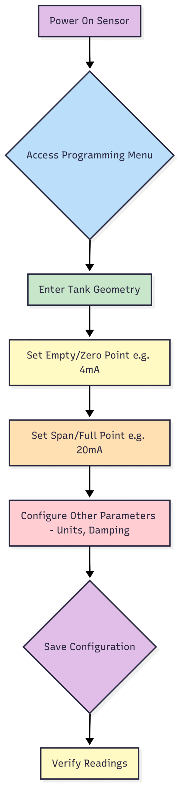
Power On the Device: Once wiring is complete and checked, apply power to the sensor.
Access the Menu: You can typically program the sensor via a built-in display with buttons, a handheld HART communicator, or a PC with the appropriate software.
Enter Key Parameters:
Units: Select your desired units of measurement (e.g., meters, feet, inches, percent).
Empty Distance (or Zero Point): This is the distance from the sensor’s face to the bottom of the tank (or your defined 0% level). You will need an accurate manual measurement for this. This setting corresponds to the low-level output (e.g., 4mA).
Span or Full Distance: This is the distance from the sensor’s face to your defined maximum fill level (the 100% point). This corresponds to the high-level output (e.g., 20mA). The difference between the Empty and Span distances is the measurement range.
Response Rate (Damping): This setting controls how quickly the sensor’s output updates in response to changing levels. A fast response is good for tracking rapid filling, while a slower (more damped) response is useful for averaging out surface turbulence to provide a more stable reading.
False Echo Suppression: Many modern sensors have a feature that allows you to create a “map” of the tank. This process lets the sensor learn the position of fixed obstructions (like pipes or ladders) so it can ignore the echoes they create and focus only on the true material level echo. This is an invaluable tool for tanks that are not perfectly clear.
Save and Verify: Once all parameters are entered, save the configuration. The sensor should now start displaying a level reading.
Phase 5: Calibration – Fine-Tuning for Precision
For many applications, the initial commissioning using manually measured empty and span distances (a “dry” calibration) is sufficient. However, for processes requiring higher accuracy, a “wet” two-point calibration is recommended.
Step 1: Set the Low Point (4mA / 0%): Bring the material level to a known low point (e.g., empty or a specific low level). Allow the reading to stabilize, then use the sensor’s programming interface to tell it, “This level equals 0%.”
Step 2: Set the High Point (20mA / 100%): Fill the tank to a known high point. Again, allow the reading to stabilize and then program the sensor to recognize this level as 100%.
The sensor will now have a precise correlation between its measured distances and the actual low and high points in your vessel, correcting for any minor irregularities.
Phase 6: Troubleshooting Common Problems
Even with a perfect installation, issues can sometimes arise. Here’s a quick guide to diagnosing common problems.
Conclusion
Installing and commissioning an ultrasonic level sensor is a straightforward process when approached with care and attention to detail. By investing time in proper planning, adhering to mounting best practices, and methodically configuring the device, you can unlock the full potential of this powerful and versatile technology. A well-installed sensor is a reliable sensor, providing the accurate data you need to optimize your processes, ensure safety, and improve your bottom line. Always remember that the manufacturer’s instruction manual is your most trusted resource, and when in doubt, don’t hesitate to reach out to their technical support experts for guidance.