
Installing Displacer Level Transmitters for Accurate Level Measurement: A Comprehensive Guide
In the world of industrial process control, accurate and reliable level measurement is paramount. For decades, displacer level transmitters have been a trusted and widely used technology for this critical task. Their robustness and dependability make them a go-to choice in various industries, from oil and gas to chemical processing and power generation.
This in-depth guide will walk you through everything you need to know about displacer level transmitters, from their fundamental working principle to detailed installation procedures, calibration, maintenance, and troubleshooting. We’ll also explore their advantages and disadvantages to help you determine if they are the right fit for your application.
Understanding the Inner Workings: The Principle of Buoyancy
At the heart of every displacer level transmitter lies a simple yet elegant principle of physics: Archimedes’ principle of buoyancy. This principle states that the buoyant force exerted on a submerged or floating body is equal to the weight of the fluid displaced by the body.
A displacer level transmitter consists of a displacer element, which is a weighted cylinder or other shaped object, suspended within a chamber or directly in the process vessel. This displacer is denser than the process fluid and is connected to a torque tube or a spring mechanism, which in turn is linked to the transmitter’s sensing element.
Here’s a step-by-step breakdown of how it works:
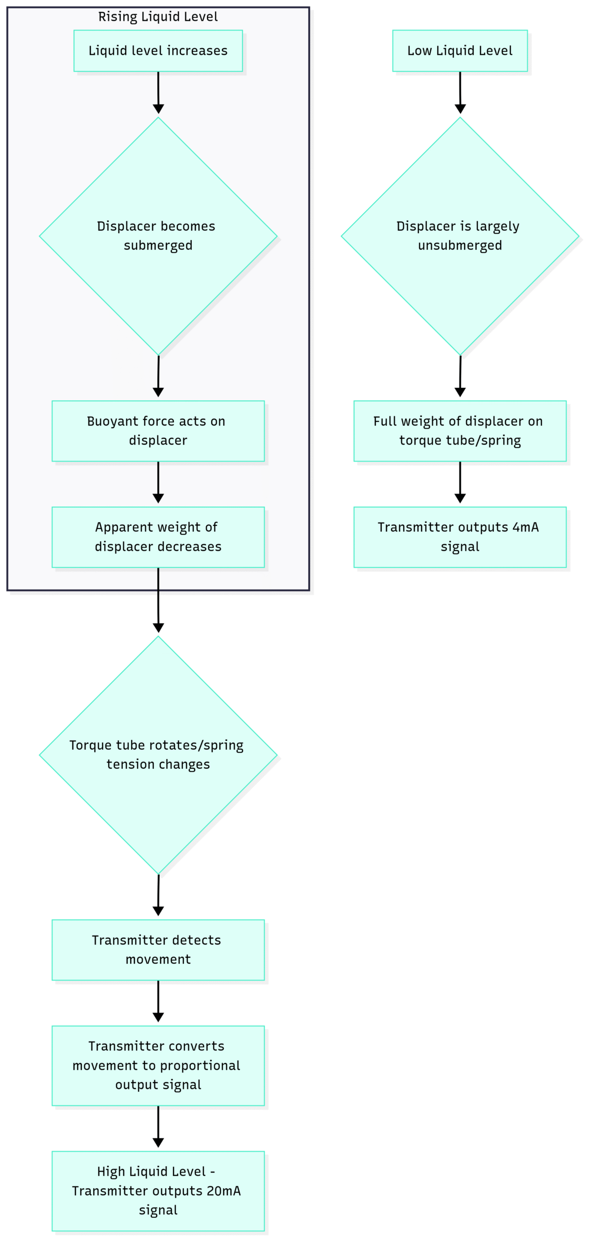
Initial State (Low Level): When the liquid level is low, the displacer is largely unsubmerged. In this state, the full weight of the displacer is supported by the torque tube or spring.
Rising Liquid Level: As the liquid level in the vessel rises, it starts to submerge the displacer.
Buoyant Force in Action: The submerged portion of the displacer experiences an upward buoyant force from the liquid. This buoyant force is directly proportional to the volume of the displaced liquid.
Apparent Weight Change: The upward buoyant force counteracts the downward force of the displacer’s weight, causing a decrease in its apparent weight. The higher the liquid level, the greater the buoyant force and the lower the apparent weight of the displacer.
Torque or Spring Movement: This change in apparent weight causes a minute rotational movement in the torque tube or a change in the tension of the spring.
Signal Conversion: The transmitter’s electronic or pneumatic components detect this mechanical movement and convert it into a proportional output signal, typically a 4-20 mA analog signal or a digital signal (like HART or Fieldbus). This signal accurately represents the liquid level.
Weighing the Options: Advantages and Disadvantages
Like any technology, displacer level transmitters have their own set of strengths and weaknesses. Understanding these will help you make an informed decision for your specific application.
Key Advantages:
High Reliability: Displacer transmitters are known for their robust and proven design, offering long-term reliability in harsh industrial environments.
Accuracy and Repeatability: When properly calibrated, they provide accurate and repeatable level measurements.
Suitable for a Wide Range of Applications: They can be used for measuring the level of clean liquids, slurries, and even the interface between two immiscible liquids.
High-Pressure and High-Temperature Capabilities: Displacer transmitters are well-suited for applications involving high pressures and extreme temperatures.
Unaffected by Many Process Variables: The measurement is largely unaffected by changes in process pressure, temperature (within limits), and the presence of vapors.
Potential Disadvantages:
Moving Parts: The presence of moving parts, such as the displacer and torque tube, means they can be susceptible to wear and tear over time, requiring periodic maintenance.
Sensitivity to Density Changes: The measurement is directly affected by changes in the specific gravity (density) of the process fluid. Any variation in density will lead to inaccuracies unless compensated for.
Installation Complexity: Installation can be more involved compared to some non-contact level measurement technologies.
Cost: Displacer transmitters can have a higher initial cost compared to some other level sensors.
Potential for Buildup: In applications with sticky or scaling fluids, material buildup on the displacer can affect its weight and lead to measurement errors.
The Blueprint for Success: A Step-by-Step Installation Guide
Proper installation is the cornerstone of accurate and reliable level measurement. A poorly installed displacer level transmitter will lead to operational headaches and inaccurate data. Here’s a detailed guide to ensure a successful installation.
Pre-Installation Checklist:
Verify Specifications: Double-check that the displacer transmitter’s materials of construction, pressure and temperature ratings, and measurement range are suitable for the intended process conditions.
Gather Necessary Tools and Equipment: This typically includes wrenches, pipe sealant, gaskets, a level, and any required lifting equipment for larger units.
Inspect the Equipment: Before installation, carefully inspect the transmitter, displacer, and any accompanying components for any signs of damage that may have occurred during shipping or handling.
Review Manufacturer’s Instructions: Always consult the manufacturer’s specific installation manual for detailed instructions and recommendations.
Installation Procedure:
Mounting the Chamber or Nozzle:
External Cage/Chamber Installation: Most displacer transmitters are installed in an external cage or chamber that is connected to the process vessel via two process connections (tappings). This arrangement ensures that the liquid level in the chamber is the same as in the vessel.
Direct Vessel Mounting: In some cases, the displacer can be mounted directly into the vessel through a top nozzle. This is less common and requires careful consideration of internal vessel components.
Ensuring Proper Orientation:
The chamber must be mounted perfectly plumb (vertical). Any tilting will cause the displacer to touch the chamber walls, leading to friction and inaccurate readings. Use a spirit level to verify verticality.
The process connections should be at the correct elevations to cover the desired measurement range.
Connecting the Process Piping:
Use appropriate gaskets and pipe sealant to ensure leak-free connections.
The piping should be properly supported to avoid putting stress on the transmitter’s connections.
Ensure that the process isolation valves are installed correctly and are easily accessible.
Installing the Displacer and Torque Tube Assembly:
Carefully lower the displacer into the chamber, ensuring it does not get damaged.
Follow the manufacturer’s instructions for attaching the displacer to the torque tube arm. This connection is critical for accurate transmission of the buoyant force.
Ensure that the displacer hangs freely and does not touch the sides of the chamber.
Wiring the Transmitter:
Connect the power and signal wiring according to the wiring diagram provided in the manufacturer’s manual.
Use appropriate conduits and fittings to protect the wiring from the environment.
Ensure proper grounding to prevent electrical noise and interference.
Achieving Precision: The Art of Calibration
Calibration is the process of adjusting the transmitter’s output to accurately correspond to the measured liquid level. A properly calibrated displacer level transmitter is essential for process control and safety.
There are two primary methods for calibrating a displacer level transmitter:
Wet Calibration (Process Fluid Calibration): This is the most accurate method as it uses the actual process fluid at its normal operating conditions.
Dry Calibration (Bench Calibration): This method is performed in a workshop or on the bench and simulates the buoyant forces using weights.
Wet Calibration Procedure:
Isolate the Transmitter: Isolate the transmitter’s chamber from the main process vessel by closing the block valves.
Establish the 0% Level (Lower Range Value – LRV): Drain the liquid from the chamber completely. The transmitter should now be reading the 0% level. Adjust the “Zero” or “LRV” setting on the transmitter until the output signal is 4.0 mA.
Establish the 100% Level (Upper Range Value – URV): Slowly fill the chamber with the process fluid until the liquid level reaches the upper process connection (the 100% mark).
Adjust the Span: With the chamber full, adjust the “Span” or “URV” setting on the transmitter until the output signal is 20.0 mA.
Verify Linearity: It’s good practice to check the linearity at intermediate points (e.g., 25%, 50%, 75%) by partially draining or filling the chamber and verifying the corresponding output signal.
Dry Calibration (Bench Calibration) with Weights:
When using the process fluid is not feasible, a dry calibration can be performed using weights to simulate the buoyant force.
Determine Displacer Weight: Accurately weigh the displacer.
Calculate Buoyant Force: Calculate the buoyant force at 100% submergence using the formula:
Simulate 0% Level: With the displacer removed, the transmitter is experiencing the full weight of the displacer arm. This may not be a true zero. The manufacturer will provide specific instructions or weights to simulate the 0% level. Adjust the “Zero” or “LRV” to 4.0 mA.
Simulate 100% Level: Apply a weight equal to the calculated buoyant force in an upward direction on the torque tube arm. This simulates the effect of the liquid at the 100% level. Adjust the “Span” or “URV” to 20.0 mA.
Ensuring Longevity: Maintenance and Troubleshooting
Regular maintenance is key to ensuring the long-term accuracy and reliability of your displacer level transmitter. Here are some essential maintenance practices and common troubleshooting tips.
Routine Maintenance Checklist:
Visual Inspection: Regularly inspect the transmitter, chamber, and piping for any signs of corrosion, leaks, or physical damage.
Cleaning: If the process fluid is known to cause buildup, schedule periodic cleaning of the displacer and the inside of the chamber.
Calibration Verification: Periodically verify the transmitter’s calibration against a known reference, such as a sight glass.
Torque Tube Inspection: For critical applications, consider periodic inspection of the torque tube for any signs of fatigue or corrosion, especially in high-pressure or corrosive services.
Common Troubleshooting Scenarios:
Conclusion: A Timeless and Trusted Technology
Displacer level transmitters have stood the test of time for a reason. Their robust design, high reliability, and accuracy make them an excellent choice for a wide array of level measurement applications. By understanding their working principle, following proper installation procedures, and implementing a regular maintenance schedule, you can ensure that your displacer level transmitters provide years of dependable service, contributing to the safety and efficiency of your operations.
While newer technologies have emerged, the fundamental simplicity and effectiveness of the displacer level transmitter ensure its continued relevance in the ever-evolving landscape of industrial automation. When you need a level measurement solution you can count on, the displacer transmitter remains a powerful and trustworthy option.