
Step-by-Step Guide to Installing RTDs in Process Plants
In the complex and demanding environment of a process plant, precision is everything. From chemical reactors to distillation columns, maintaining the correct temperature is not just a matter of efficiency or product quality—it’s a critical safety requirement. Among the various tools for temperature measurement, the Resistance Temperature Detector (RTD) stands out for its accuracy, stability, and reliability. However, an RTD is only as good as its installation.
A poorly installed sensor can lead to inaccurate readings, process upsets, costly downtime, and even hazardous conditions. This guide provides a comprehensive, step-by-step approach to properly installing RTDs in a process plant setting. We’ll cover everything from pre-installation planning and component selection to wiring, commissioning, and troubleshooting. Whether you’re a seasoned instrument technician or an engineer new to the field, this guide will serve as your go-to resource for ensuring flawless RTD installation.
Part 1: Pre-Installation Planning & Preparation
Success in any technical task begins with meticulous planning. Before you even touch a tool, a significant amount of groundwork is required to ensure the installation is safe, efficient, and effective. Rushing this stage is a common mistake that often leads to problems down the line.
Understanding Your Process Requirements
The first step is to thoroughly understand the environment where the RTD will operate. You must gather critical data about the process itself. Ask these key questions:
What is the normal operating temperature range? And what are the maximum and minimum possible temperatures, including upset conditions or startup/shutdown sequences? This determines the required range of the RTD and transmitter.
What is the operating pressure? The thermowell must be rated to withstand the maximum process pressure safely.
What is the process medium? Is it a corrosive liquid, an abrasive slurry, a clean gas, or high-purity steam? The material of the thermowell must be chemically compatible with the medium to prevent corrosion and failure.
What is the fluid velocity? High flow rates can induce vibration in the thermowell. A Wake Frequency Calculation is often required (per ASME PTC 19.3 TW standard) to ensure the thermowell’s design prevents resonance and potential mechanical failure.
What is the required response time? How quickly does the measurement need to react to changes in process temperature? This can influence the type of RTD and thermowell design.
Choosing the Right RTD Sensor
With the process data in hand, you can select the appropriate RTD. The most common type used in process industries is the Pt100, which has a resistance of 100 ohms at 0°C. Pt1000 sensors (1000 ohms at 0°C) are also available and are sometimes preferred for battery-powered applications due to their lower power consumption.
Key selection criteria include:
Element Type: Thin-film RTDs are cost-effective and vibration-resistant, making them suitable for many applications. Wire-wound elements offer higher accuracy and stability, ideal for custody transfer or critical control loops.
Accuracy Class: RTDs come in different accuracy classes (e.g., Class A, Class B per IEC 60751). Class A offers tighter tolerance and is used for critical measurements, while Class B is suitable for general monitoring.
Sheath Material: The protective sheath, typically made of 316 Stainless Steel or Inconel, must withstand the process temperature and environment.
Configuration: The RTD will be configured for 2, 3, or 4-wire measurement. We will cover this in detail in the wiring section, but the choice depends on the required accuracy and the distance to the transmitter. For industrial process control, a 3-wire or 4-wire configuration is almost always the correct choice.
The Critical Role of the Thermowell
The thermowell is arguably as important as the sensor itself. It’s a permanent, pressure-tight receptacle that protects the RTD from the process medium. This allows the sensor to be removed and replaced for calibration or maintenance without shutting down or draining the process.
Here’s a diagram illustrating the decision-making process for thermowell selection:
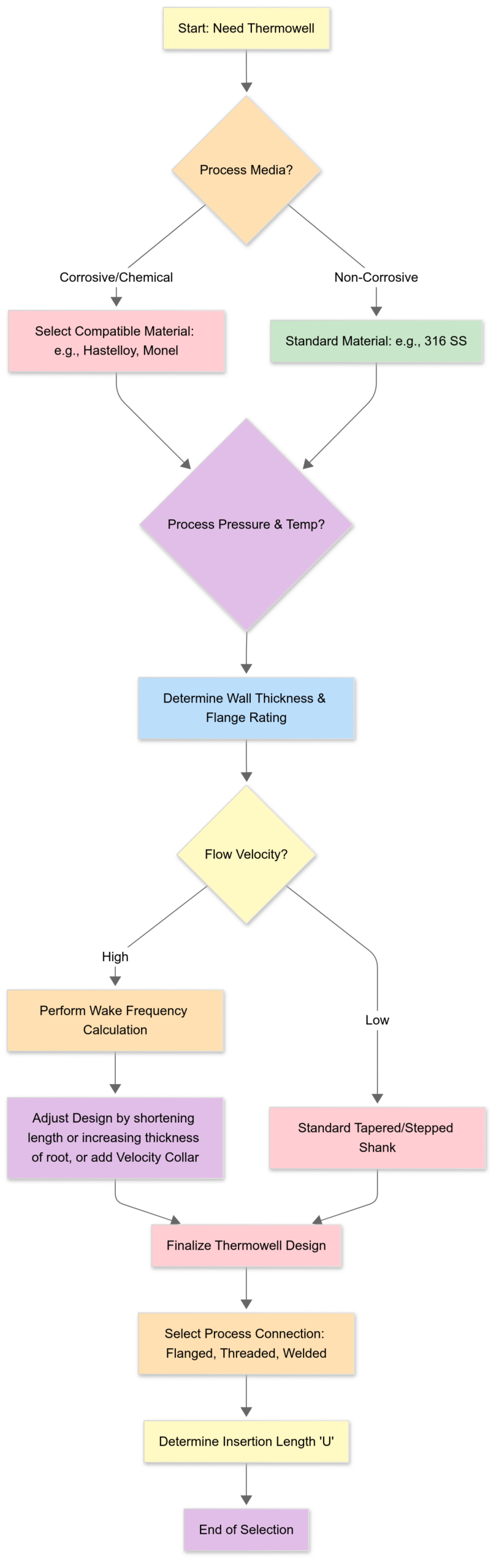
Material: As mentioned, the material (e.g., 316 Stainless Steel, Hastelloy C-276, Monel) must resist corrosion from the process fluid.
Process Connection: This can be threaded (NPT), flanged (RF/FF), or weld-in. Flanged connections are common in hydrocarbon industries for safety and reliability.
Insertion Length (U-Length): This is the length of the thermowell from the underside of the connection to the tip. It must be long enough for the RTD tip to be positioned in the most representative part of the process fluid, typically the center third of the pipe, but not so long that it creates excessive flow restriction or vibration risk.
Shank Style: Thermowells can be straight, stepped, or tapered. Tapered thermowells offer the best strength against vibration and are the standard for demanding applications.
Site Assessment and Tools Checklist
Finally, survey the physical installation location.
Ensure there is sufficient clearance to install the thermowell and to remove the RTD probe later. A standard rule of thumb is to have at least the RTD’s length plus one foot of straight clearance.
Identify the route for the signal cable back to the junction box or control system. Keep it away from sources of electromagnetic interference (EMI) like large motors or power cables.
Prepare your tools and materials.
Essential Tools & Materials:
Personal Protective Equipment (PPE): Safety glasses, gloves, hard hat, etc.
Lock-Out/Tag-Out (LOTO) kit
Wrenches (pipe wrench, adjustable wrenches, flange-specific torque wrench)
Thread sealant or appropriate flange gasket
Wire strippers and crimpers
Screwdriver set
Digital Multimeter (DMM)
Portable temperature calibrator (dry block)
RTD sensor, thermowell, and connection head/transmitter
Instrumentation cable (with shield)
Cable glands and conduit fittings
Part 2: The Step-by-Step Installation Process
With planning complete and materials gathered, it’s time to begin the physical installation. Follow these steps methodically to ensure a safe and successful outcome.
Step 1: Safety First! Lock-Out/Tag-Out (LOTO)
This is the most important step. Before starting any work on process piping or equipment, you must ensure the line is de-pressurized, drained, vented, and isolated.
Obtain a Permit to Work: Follow your plant’s specific safety procedures.
Isolate the Equipment: Close the appropriate isolation valves.
Apply Locks and Tags: Physically lock the valves in the closed position and attach tags that clearly state “Do Not Operate.” This ensures that no one can accidentally re-energize the system while you are working on it.
Verify Zero Energy: Confirm that the line is fully depressurized and drained before proceeding.
Step 2: Preparing the Installation Point
If a suitable installation port (like a threaded o-let or flange) doesn’t already exist, one must be created. This typically involves hot work (welding) and must be done by certified personnel according to approved procedures, especially on pressure-containing equipment.
For Welded Connections: A certified welder attaches a “sockolet” or flange to the pipe at the designated location. This requires post-weld heat treatment and non-destructive examination (NDE) in many services.
For Threaded Connections: Ensure the existing threads are clean and undamaged. Use a wire brush to remove any old sealant, rust, or debris.
Step 3: Installing the Thermowell
The thermowell forms the primary pressure boundary. Its integrity is paramount.
Inspect the Thermowell: Check for any signs of damage from shipping, such as bent shanks or damaged threads/flange faces.
Apply Sealant (Threaded): For threaded connections, apply a suitable, process-compatible thread sealant (like PTFE tape or paste) to the male threads of the thermowell. Do not over-apply.
Install the Gasket (Flanged): For flanged connections, place a new, correct-specification gasket onto the flange face. Never reuse old gaskets.
Tighten the Connection:
Threaded: Screw the thermowell in hand-tight, then use a wrench to tighten it securely. Avoid over-tightening, which can damage the threads.
Flanged: Insert the bolts and tighten them in a star or crisscross pattern to ensure even pressure on the gasket. Use a torque wrench to apply the correct bolt torque as specified by engineering standards.
Step 4: Inserting the RTD into the Thermowell
With the thermowell securely in place, you can now install the sensor probe.
Inspect the RTD: Check the probe for any bends or damage. Verify it’s the correct model and length (‘U’ length).
Ensure Good Thermal Contact: For optimal heat transfer from the thermowell to the RTD tip, the probe should be a snug fit and bottom out inside the well. Spring-loaded RTDs are highly recommended as they ensure positive contact with the bottom of the thermowell, even with thermal expansion and contraction.
Insert the Probe: Gently slide the RTD probe into the thermowell until it bottoms out. If it’s a spring-loaded assembly, you’ll feel the spring compress slightly. Secure the connection head or fitting to the top of the thermowell.
Step 5: Wiring the RTD
Correct wiring is crucial for accuracy. An incorrect connection is one of the most common sources of error. RTDs use the principle that a metal’s resistance changes predictably with temperature. The wiring’s job is to carry this resistance signal to the measuring instrument without adding its own resistance to the measurement.
Here is a breakdown of the common wiring schemes:
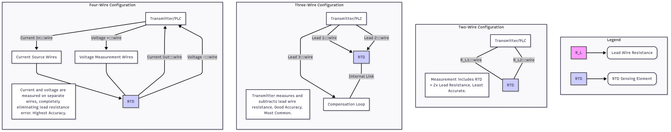
2-Wire RTD: The simplest but least accurate. The instrument measures the total resistance of the RTD element plus the two lead wires. This added resistance from the wires creates a positive error, making the temperature read higher than it actually is. This configuration should be avoided in process control unless the wires are very short.
3-Wire RTD: The most common configuration in industrial plants. It uses a third wire to create a compensation loop. The transmitter or PLC sends a current down one wire, through the RTD, and back on the second. The third wire allows the instrument to measure the resistance of the lead wire itself and subtract it from the total measurement. This effectively cancels out the lead wire resistance error, assuming all three wires are the same length and material.
4-Wire RTD: The most accurate configuration, often used in laboratory or custody-transfer applications. Two wires supply a precise, constant current through the RTD. The other two wires, connected to the same points, measure the voltage drop across the RTD element. Since a high-impedance voltmeter draws virtually no current, the resistance of these voltage-measuring leads has no effect on the reading. This method completely eliminates lead wire resistance as a source of error.
Wiring Procedure:
Run the shielded instrumentation cable from the RTD connection head to the transmitter or junction box.
Strip the ends of the wires carefully.
Connect the wires to the terminals in the RTD head and at the transmitter/PLC, following the manufacturer’s diagrams. Pay close attention to the color codes and terminal numbers. A common scheme is two red wires and one white wire for a 3-wire Pt100. The two red wires are the compensation leads.
Connect the cable shield (drain wire) to the instrument ground at one end only (usually the control system end) to prevent ground loops, which can induce noise. Leave the shield unterminated at the sensor end.
Part 3: Commissioning, Verification, and Troubleshooting
The installation isn’t complete once the last wire is connected. Verification is essential to ensure the measurement is accurate and reliable before handing it over to Operations.
Commissioning and Loop Checks
Continuity and Resistance Check: Before powering up, use a DMM to check the resistance. For a Pt100 at ambient temperature (~25°C), you should read approximately 109.7 ohms. Check for continuity on all wires and ensure there are no shorts to ground.
Power Up: Apply power to the instrument loop.
Verify Reading: Check the reading on the local display or in the Distributed Control System (DCS). It should show a plausible temperature for the current process condition (which may be ambient if the line is shut down).
Perform a Loop Check: This is a full, end-to-end verification.
At the Sensor: Disconnect the RTD and connect a portable calibrator or decade resistance box.
Simulate Temperatures: Input known resistance values corresponding to 0%, 25%, 50%, 75%, and 100% of the instrument’s calibrated range.
Verify in DCS: Have a second person in the control room verify that the readings received in the DCS match the simulated inputs at each step. This confirms the entire circuit—wiring, transmitter configuration, and DCS scaling—is correct.
Documentation
Proper documentation is vital for future maintenance and troubleshooting. Update all relevant documents:
Loop Diagrams: Show the complete circuit from sensor to control system.
P&ID (Piping and Instrumentation Diagram): Ensure the tag number and location are correct.
Instrument Database: Update calibration dates, model numbers, and location details.
Common Pitfalls and Troubleshooting Installing RTDs
Conclusion: Precision Through Diligence
Installing an RTD is more than just connecting a few wires. It’s a precise engineering task that directly impacts plant safety, efficiency, and product quality. By embracing a diligent, step-by-step approach—from meticulous pre-planning and component selection to careful installation and thorough verification—you ensure that your temperature measurements are not just numbers on a screen, but accurate, reliable data that can be trusted. A well-installed RTD is a silent, dependable guardian of your process, working 24/7 to keep operations running smoothly and safely for years to come.