
Pyrometer Installation Guidelines for High-Temperature Applications
In modern industries, from steel foundries and glass manufacturing to semiconductor fabrication and power generation, accurately measuring and controlling high temperatures is not just a procedural step—it’s the cornerstone of quality, efficiency, and safety. When contact-based sensors like thermocouples are impractical or impossible to use, non-contact infrared (IR) pyrometers become the indispensable tool for the job. However, the accuracy of these sophisticated instruments hinges entirely on their correct installation.
An improperly installed pyrometer can lead to erroneous readings, resulting in poor product quality, increased energy consumption, damaged equipment, and significant safety hazards. This comprehensive guide provides detailed, step-by-step instructions and expert tips for installing pyrometers in demanding high-temperature applications. Following these guidelines will ensure you achieve reliable, repeatable, and accurate temperature data, empowering you to optimize your critical processes.
Part 1: Understanding the Fundamentals of Pyrometry
Before diving into the physical installation, it’s crucial to grasp the principles that govern how a pyrometer works. A pyrometer measures temperature by detecting the thermal radiation emitted by an object. All objects above absolute zero (-273.15°C) emit this energy, and the intensity of the radiation increases proportionally with the object’s temperature. The pyrometer’s optical system collects this infrared energy and focuses it onto a detector, which converts it into an electrical signal that is then processed and displayed as a temperature reading.
Three key concepts are fundamental to a successful installation:
Emissivity ()
Emissivity is a measure of an object’s ability to emit thermal radiation compared to a perfect emitter, known as a blackbody ( = 1.0). In reality, most materials are “graybodies,” meaning they have an emissivity value between 0 and 1.0. For example, oxidized steel has a high emissivity (around 0.85), while a polished, reflective surface like aluminum has a very low emissivity (as low as 0.05).
Why it matters: The pyrometer’s electronics use the emissivity value to correctly calculate the temperature. Setting an incorrect emissivity value is one of the most common sources of error in non-contact temperature measurement. An emissivity setting that is too high will result in a temperature reading that is too low, and vice versa. The material’s surface condition (e.g., oxidized, polished, rough), as well as the material itself, dramatically affects its emissivity.
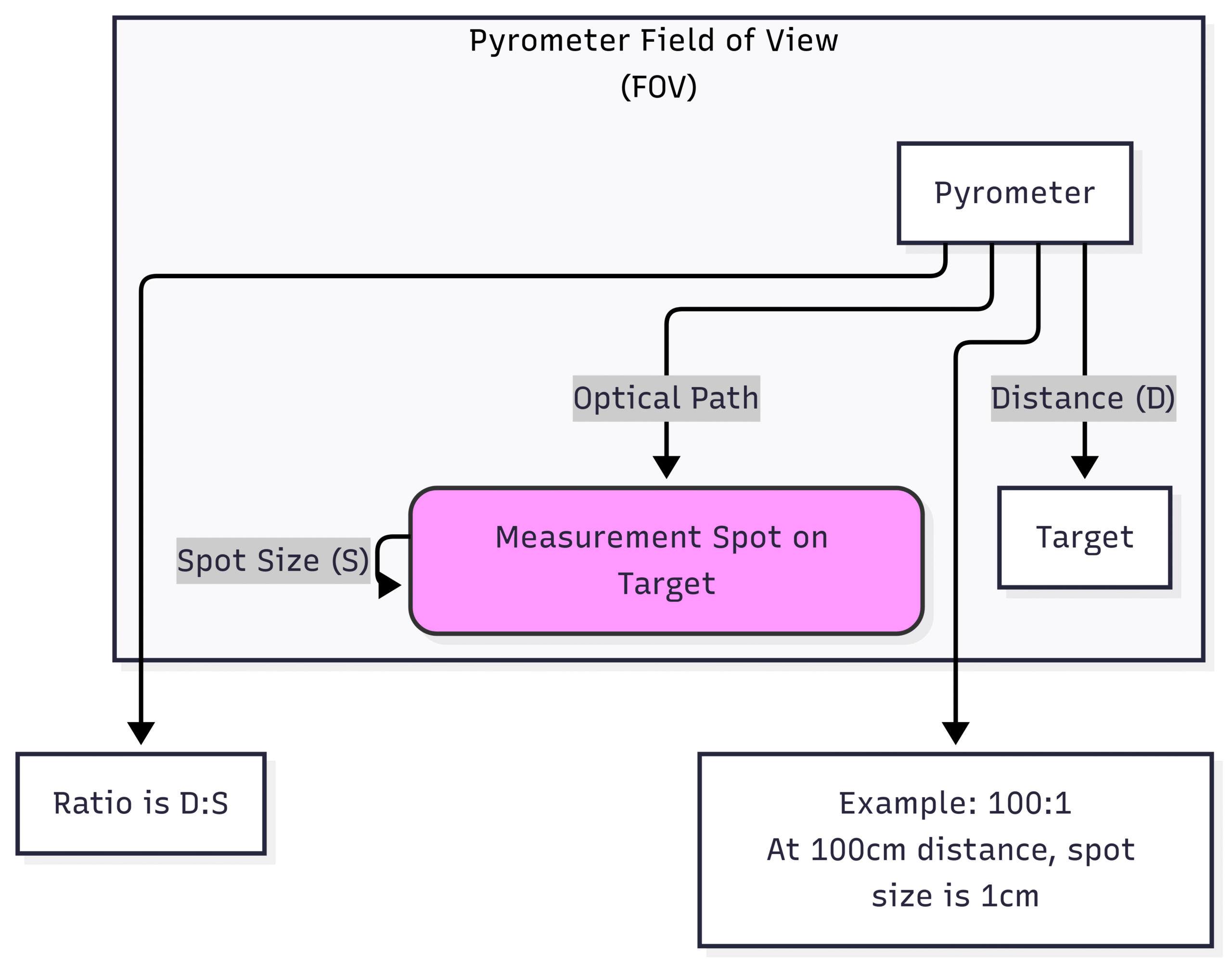
Field of View (FOV) and Spot Size
The Field of View (FOV) is the area or “spot” on the target surface that the pyrometer is measuring. It’s typically expressed as a distance-to-spot-size ratio (D:S). For example, a pyrometer with a D:S ratio of 100:1 will measure a 1-inch diameter spot from a distance of 100 inches.
Why it matters: For an accurate measurement, the target object must completely fill the pyrometer’s measurement spot. If the spot size is larger than the target, the pyrometer will average the temperature of the target and the cooler background, leading to a significantly lower and incorrect reading. A common rule of thumb is to ensure the target is at least twice the size of the measurement spot to account for any slight misalignment or vibration.
Pyrometers are designed to operate within specific wavelength bands (or spectral ranges) of the infrared spectrum.
Long-Wavelength (8-14 µm): Best for general-purpose, low-temperature applications (below 500°C) and for measuring organic materials, plastics, and coated surfaces.
Short-Wavelength (e.g., 1.0, 1.6, or 2.3 µm): Crucial for high-temperature applications, especially for metals. Short-wavelength pyrometers are less sensitive to emissivity variations and are better at “seeing” through atmospheric interferents like steam, water vapor, and combustion gases.
Ratio (Two-Color) Pyrometers: These measure energy at two different wavelengths simultaneously. They calculate temperature based on the ratio of the two signals. This makes them ideal for applications where the target is partially obscured by dust, smoke, or steam, or where the emissivity is unknown or changing.
Why it matters: Selecting the correct spectral response for your application is non-negotiable for accuracy in challenging high-temperature environments. Using a long-wavelength unit to measure molten metal through steam will yield useless results.
Part 2: Pre-Installation Checklist: Paving the Way for Accuracy
Thorough preparation is half the battle. Before you even pick up a wrench, work through this checklist to prevent common pitfalls.
Confirm Pyrometer Selection: Double-check that the chosen pyrometer’s specifications match the application’s requirements:
Temperature Range: Does it cover the minimum and maximum process temperatures?
Spectral Response: Is it a short-wavelength model suitable for high-temperature metals or a ratio pyrometer for obscured targets?
Optics/FOV: Will you be able to mount the pyrometer at a distance that provides a suitable spot size for your target?
Response Time: Is it fast enough to capture temperature changes in dynamic processes?
Analyze the Target Material:
What is the material being measured (e.g., steel, refractory, glass, ceramic)?
What is its surface condition? Is it clean, oxidized, scaly, or molten?
Determine the emissivity value. Use standard emissivity tables as a starting point, but be prepared to fine-tune it. If possible, perform a reference measurement with a calibrated contact probe on a test piece to determine the precise emissivity setting.
Survey the Installation Site:
Line of Sight: Is there a clear, unobstructed view of the target? Avoid paths that pass through flames (unless using a special flame-filtering pyrometer), heavy smoke, or steam.
Ambient Temperature: What is the temperature around the intended mounting location? Most standard pyrometers have an upper ambient temperature limit of around 60-70°C. Exceeding this will damage the electronics.
Vibration: Is the proposed mounting structure subject to heavy vibration from machinery?
Contaminants: Is the atmosphere dusty, steamy, or corrosive? This will determine the need for protective accessories.
Electromagnetic Interference (EMI): Are there large motors, induction heaters, or high-voltage cables nearby? EMI can corrupt the pyrometer’s signal.
Part 3: The Core Installation Process: A Step-by-Step Guide
With your planning complete, you can proceed with the physical installation. Follow these steps methodically for the best results.
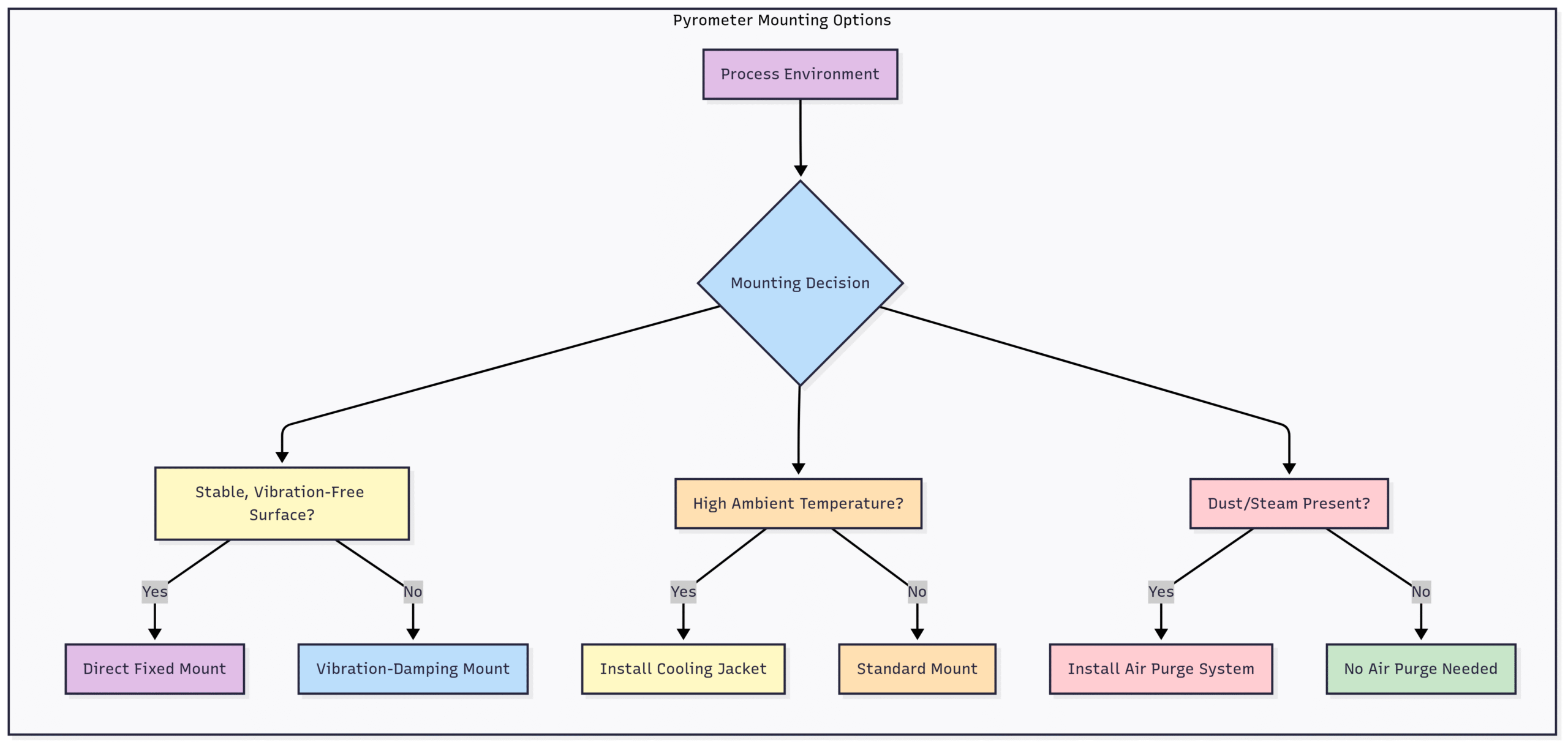
Step 1: Mechanical Mounting
The goal is to provide a stable, protected, and correctly positioned home for the pyrometer.
Stability is Key: Mount the pyrometer on a rigid, fixed surface like a steel support beam or a dedicated mounting pole. Avoid mounting it directly onto vibrating machinery. If vibration is unavoidable, use shock-absorbing mounting brackets.
Choose the Right Location: The location must provide the correct distance-to-spot ratio calculated during the pre-installation phase. Ensure there is a clear and direct line of sight to the target area.
Perpendicular Alignment: Whenever possible, mount the pyrometer perpendicular (at a 90° angle) to the target surface. This minimizes errors from emissivity variations that occur at different viewing angles. If you must mount at an angle to avoid reflections from hotter sources (like heating elements), keep the angle within 30° of perpendicular.
Use Proper Hardware: Utilize the manufacturer-supplied mounting brackets or heavy-duty industrial mounts. Ensure all bolts and fasteners are securely tightened.
Properly aiming the pyrometer is critical to ensure you are measuring the intended target.
Use the Sighting Method: Most pyrometers come with one of three sighting methods:
Through-the-Lens Sighting: Similar to an SLR camera, you look through an eyepiece to see exactly what the detector sees. This is the most accurate method.
Laser Sighting: A built-in laser marks the center or the circumference of the measurement spot. This is excellent for aiming but remember the laser is just an indicator; it is not what’s performing the measurement.
Video Sighting: High-end models feature a built-in video camera that shows the target and the measurement spot on a remote monitor, ideal for inaccessible or hazardous locations.
Fill the Spot: As emphasized earlier, the target must completely fill the pyrometer’s measurement spot. Aim for the center of the target area. If measuring a moving object (e.g., a steel strip), ensure the spot stays on the target throughout its travel. If the target is smaller than the smallest possible spot size, you must move the pyrometer closer.
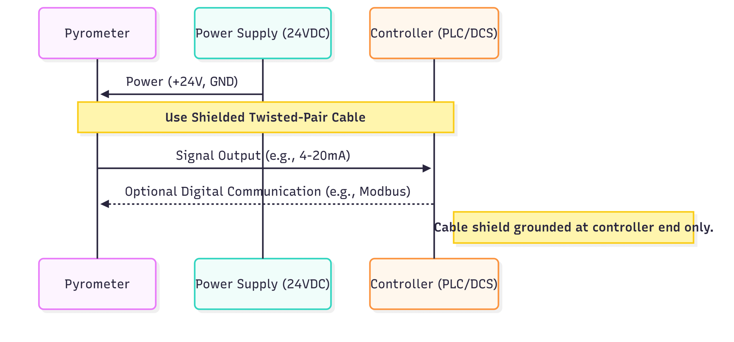
Step 3: Electrical Connections and Wiring
Clean and correct wiring is essential for a noise-free, reliable signal.
Power Supply: Use a dedicated, regulated power supply that meets the voltage and current requirements specified in the pyrometer’s manual (typically 24 VDC). Do not share the power supply with high-power-switching devices like solenoids or motor drives.
Signal Output: Connect the signal output wires (e.g., 4-20 mA, 0-10 V, or digital outputs like Modbus/Profinet) to your PLC, controller, or data acquisition system.
Use Shielded Cable: Always use shielded, twisted-pair cable for the signal output to protect it from electromagnetic interference (EMI). This is particularly important in industrial plants with high electrical noise.
Grounding: Ground the cable shield properly. The standard practice is to connect the shield to a good earth ground at one end only—typically at the control panel or PLC end. Connecting it at both ends can create a ground loop, which can introduce noise.
Cable Routing: Route the pyrometer cable away from high-voltage power cables, motor leads, and induction heater lines. If you must cross them, do so at a 90° angle.
Now you need to tell the pyrometer how to interpret the radiation it sees. This is typically done via onboard controls, connected software, or a handheld programmer.
Emissivity: This is the most critical setting. Enter the emissivity value you determined in the pre-installation phase. If unsure, start with a value from a table and prepare to adjust it.
Response Time / Averaging: This setting determines how quickly the pyrometer updates its reading.
For fast-moving targets or dynamic processes, use a short response time.
For stable, slow-changing processes, a longer response time (or enabling an averaging function) will help smooth out minor fluctuations and provide a more stable reading. A setting of 1-5 seconds is common for furnaces.
Alarm Setpoints: If your pyrometer has alarm relays, configure the high and low temperature setpoints to trigger alerts for out-of-spec conditions.
Peak/Valley Hold: This function is useful for measuring intermittent targets or finding the hottest spot on a moving surface. “Peak hold” (or “max hold”) will display the highest temperature seen over a defined period.
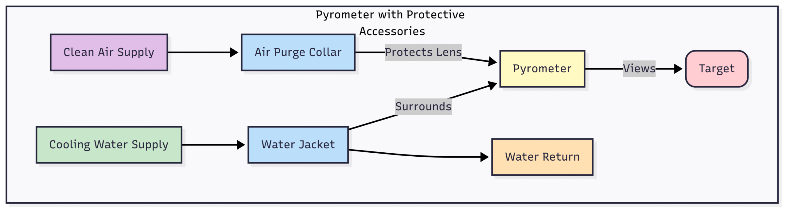
Part 4: Dealing with Environmental Challenges
High-temperature processes rarely occur in clean, temperate environments. Protective accessories are often not optional but essential.
High Ambient Temperatures
If the pyrometer is installed near a furnace, oven, or molten metal, its body can overheat.
Solution: Cooling Jackets. A protective housing that circulates either air or water around the pyrometer body. Water cooling is the most effective and can allow the pyrometer to operate in ambient temperatures of up to 315°C (600°F) or more. Air cooling is suitable for moderately hot environments.
Interference: Dust, Smoke, and Steam
Particulates in the optical path will scatter and absorb the infrared energy, causing falsely low readings.
Solution: Air Purge. An air purge collar is fitted to the front of the pyrometer lens. A steady stream of clean, dry compressed air flows out, creating a positive pressure curtain that prevents dust, fumes, and other contaminants from settling on the lens. This is a must-have in almost all foundry, cement, and power plant applications.
Reflections from hotter sources (flames, heating elements, furnace walls) can reflect off the target surface and into the pyrometer, causing falsely high readings.
Solution 1: Use a Sighting Tube. A non-reflective (e.g., ceramic) tube mounted between the pyrometer and the target can shield the optical path from stray radiation.
Solution 2: View from an Angle. As mentioned in the mounting section, angling the pyrometer slightly can prevent direct reflections from entering the lens.
Solution 3: Measure the Reflected Temperature. Advanced pyrometers have a feature to compensate for reflected energy. This involves using a second sensor to measure the background temperature and subtracting its influence from the primary measurement.
Part 5: Post-Installation: Verification and Maintenance
Your job isn’t done once the pyrometer is powered on. Regular checks ensure its continued accuracy.
Verification: At regular intervals, verify the pyrometer’s reading. The best method is to use a portable, calibrated blackbody source. Alternatively, a carefully conducted measurement with a calibrated contact thermocouple on a test piece can provide a good reference point. This allows you to fine-tune the emissivity setting if needed.
Maintenance Schedule:
Daily/Weekly: Visually inspect the pyrometer lens for any contamination. Even with an air purge, some buildup can occur over time. Clean the lens gently with a soft cloth and an appropriate cleaning solution (like isopropyl alcohol), as recommended by the manufacturer.
Monthly: Check the integrity of the mounting hardware and electrical connections. Ensure the air purge and/or water cooling systems are functioning correctly (check for proper flow and pressure).
Annually: Consider sending the pyrometer back to the manufacturer or a certified lab for a full recalibration, especially if it’s used in a critical quality control application.
Conclusion: Installation as the Foundation of Accuracy
Installing a pyrometer in a high-temperature application is far more than just mounting a sensor and connecting a wire. It is a systematic process that demands a solid understanding of the technology, careful planning, and meticulous execution.
By taking the time to select the right instrument, analyze the target and environment, mount and align it correctly, configure its settings with precision, and protect it from environmental hazards, you lay the foundation for reliable and accurate process control. A well-installed pyrometer is a powerful asset that enhances product quality, boosts energy efficiency, and ensures operational safety. Treat these guidelines not as mere suggestions, but as a critical standard operating procedure for unlocking the full potential of non-contact temperature measurement in your most demanding applications.