
Temperature Sensor Installation in Hazardous Areas: A Complete Guide
Monitoring temperature is a fundamental requirement in countless industrial processes. From chemical reactors and oil refineries to grain silos and pharmaceutical plants, precise temperature control is crucial for efficiency, quality, and, most importantly, safety. When these processes involve flammable gases, combustible dusts, or volatile liquids, the environment is classified as a hazardous area. Installing any electrical equipment, including a seemingly simple temperature sensor, in such an environment is a high-stakes task that demands meticulous planning, deep technical knowledge, and unwavering adherence to strict safety standards.
This comprehensive guide will walk you through everything you need to know about installing temperature sensors in hazardous areas. We’ll cover area classification, sensor selection, protection concepts like Intrinsic Safety and Explosion-Proof enclosures, step-by-step installation procedures, and ongoing maintenance. Our goal is to equip you with the knowledge to ensure your temperature measurement systems are not only accurate and reliable but also fundamentally safe. ⚡️
Understanding Hazardous Areas: Zones, Divisions, and Dangers
Before you can even think about installation, you must understand the environment you’re working in. A hazardous area (or hazardous location) is defined as a space where concentrations of flammable gases, vapors, mists, or combustible dusts are or may be present in the atmosphere in quantities sufficient to require special precautions for the construction, installation, and use of electrical apparatus.
International and North American standards classify these areas to systematically manage the risk.
Hazardous Area Classification Systems
Two primary systems are used globally: the IEC/ATEX Zone system and the North American Division system.
The Zone System (IEC/ATEX): Primarily used in Europe and most parts of the world, this system classifies areas based on the frequency and duration of the explosive atmosphere’s presence.
For Gas/Vapor:
Zone 0: An area where an explosive gas atmosphere is present continuously or for long periods.
Zone 1: An area where an explosive gas atmosphere is likely to occur in normal operation.
Zone 2: An area where an explosive gas atmosphere is not likely to occur in normal operation and, if it does, will persist for only a short period.
For Dust:
Zone 20: An area where an explosive atmosphere in the form of a cloud of combustible dust in the air is present continuously or for long periods.
Zone 21: An area where an explosive atmosphere in the form of a cloud of combustible dust in the air is likely to occur in normal operation.
Zone 22: An area where an explosive atmosphere in the form of a cloud of combustible dust in the air is not likely to occur in normal operation and, if it does, will persist for only a short period.
The Division System (NEC/CEC): Used in the United States and Canada.
Division 1: A location where ignitable concentrations of hazards can exist under normal operating conditions. This is roughly equivalent to a combination of Zone 0 and Zone 1.
Division 2: A location where ignitable concentrations of hazards are present only under abnormal operating conditions (e.g., a container failure). This is similar to Zone 2.
Understanding the specific Zone or Division classification of your installation area is the first and most critical step. This classification dictates the type of equipment and protection methods you are legally required to use.
Choosing the Right Temperature Sensor
With a clear understanding of the hazardous area, the next step is selecting the appropriate sensor. The two most common types used in industrial applications are Resistance Temperature Detectors (RTDs) and Thermocouples.
Resistance Temperature Detectors (RTDs): These sensors, typically made from platinum (Pt100 or Pt1000), offer high accuracy, excellent stability, and repeatability. Their resistance changes in a precise, well-documented way with temperature. They are often the preferred choice for applications requiring high precision over a moderate temperature range (e.g., -200°C to 600°C).
Thermocouples (TCs): These sensors consist of two dissimilar metal wires joined at one end. A small voltage, which is a function of temperature, is produced at this junction. Thermocouples are extremely rugged, cost-effective, and can measure a very wide range of temperatures (e.g., up to 2300°C for Type B). However, they are generally less accurate than RTDs.
Selection Considerations:
Temperature Range: Does the sensor’s operating range cover your process minimum and maximum?
Accuracy Required: Is the high precision of an RTD necessary, or is the ruggedness of a thermocouple more important?
Chemical Compatibility: The sensor sheath and any accompanying thermowell must be made of materials (like 316 Stainless Steel, Inconel, or Hastelloy) that can withstand corrosive process media. A thermowell is a protective tube that houses the sensor, allowing it to be removed for calibration or replacement without shutting down the process.
Vibration and Shock: Thermocouples are generally more robust and resistant to vibration than RTDs.
Certification: Crucially, the sensor assembly must be certified for use in the designated hazardous area. Look for markings like ATEX, IECEx, or UL/CSA that match your site’s requirements.
Protection Concepts for Hazardous Areas
You cannot simply install a standard RTD or thermocouple in a Zone 1 or Division 1 area. The sensor and its wiring must incorporate a specific protection method designed to prevent ignition. The two most dominant protection philosophies are Intrinsic Safety and Explosion-Proof containment.
Intrinsic Safety (IS) 🔥
Intrinsic Safety is a preventative protection concept. Its principle is to limit the electrical and thermal energy in a circuit to a level below that required to ignite a specific hazardous atmospheric mixture. Even under fault conditions (like a short circuit), the energy released is insufficient to cause an explosion.
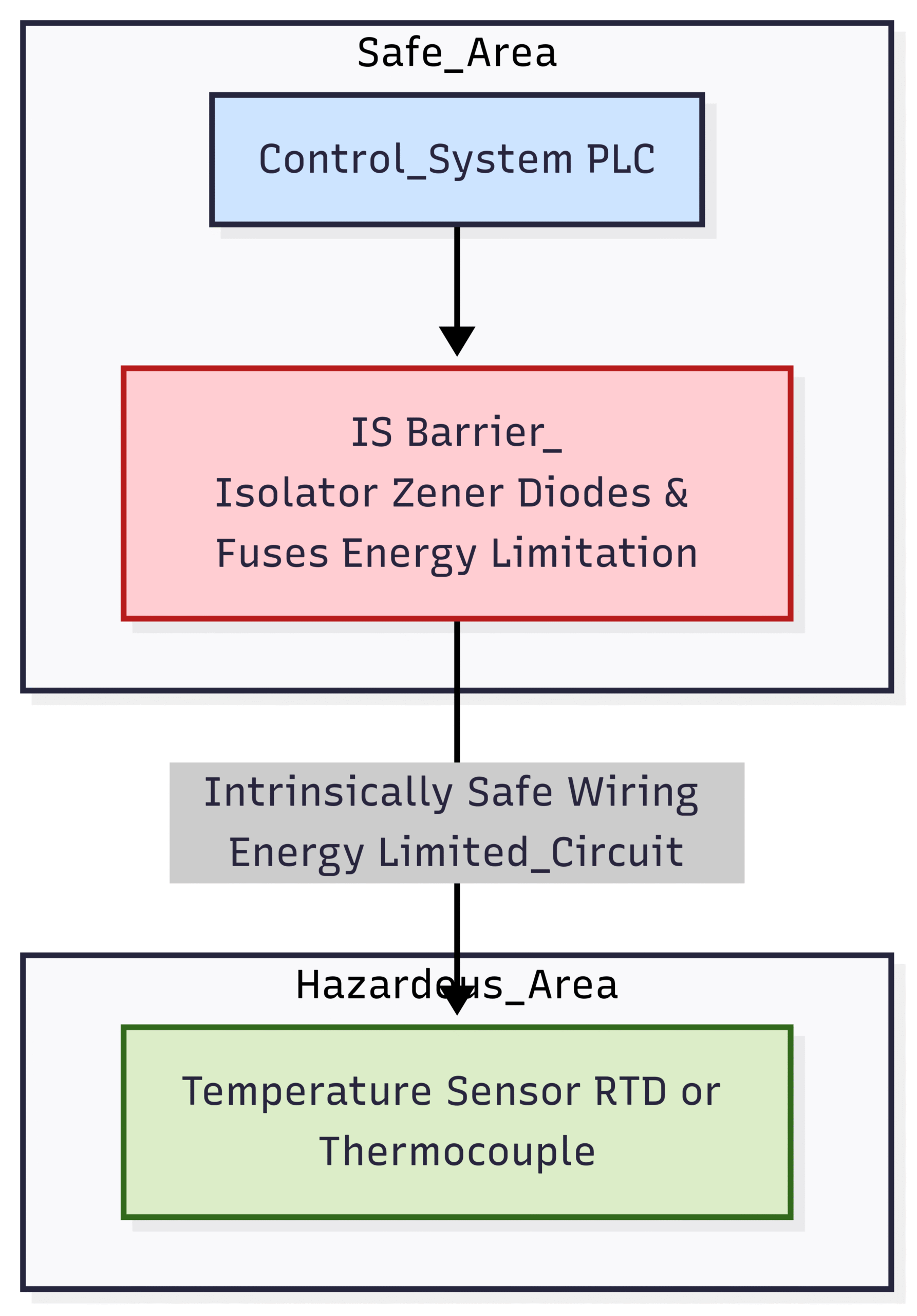
An intrinsically safe system consists of three main components:
Intrinsically Safe Field Device: The temperature sensor itself, which is designed to not store or generate significant energy.
Intrinsically Safe Barrier (or Isolator): This is the core of the system. Located in the safe area, this device regulates the amount of voltage and current sent to the sensor in the hazardous area. It uses a combination of Zener diodes, resistors, and fuses to clamp energy to safe levels.
Interconnecting Cable: The cable itself becomes part of the IS circuit, and its capacitance and inductance must be considered in the overall system design calculations.
Advantages of Intrinsic Safety:
Safety: The safest method, as it prevents the ignition source from ever existing.
Live Maintenance: Circuits can often be worked on live (with proper permits) because they are low-energy.
Cost-Effective: Uses standard instrumentation cables and glands, reducing wiring costs.
Disadvantages of Intrinsic Safety:
Limited Power: Not suitable for high-power devices.
System Design: Requires careful “loop calculations” to ensure the cable’s capacitance and inductance, combined with the sensor’s parameters, do not exceed the barrier’s certified limits.
Explosion-Proof / Flameproof (Ex d) 💣
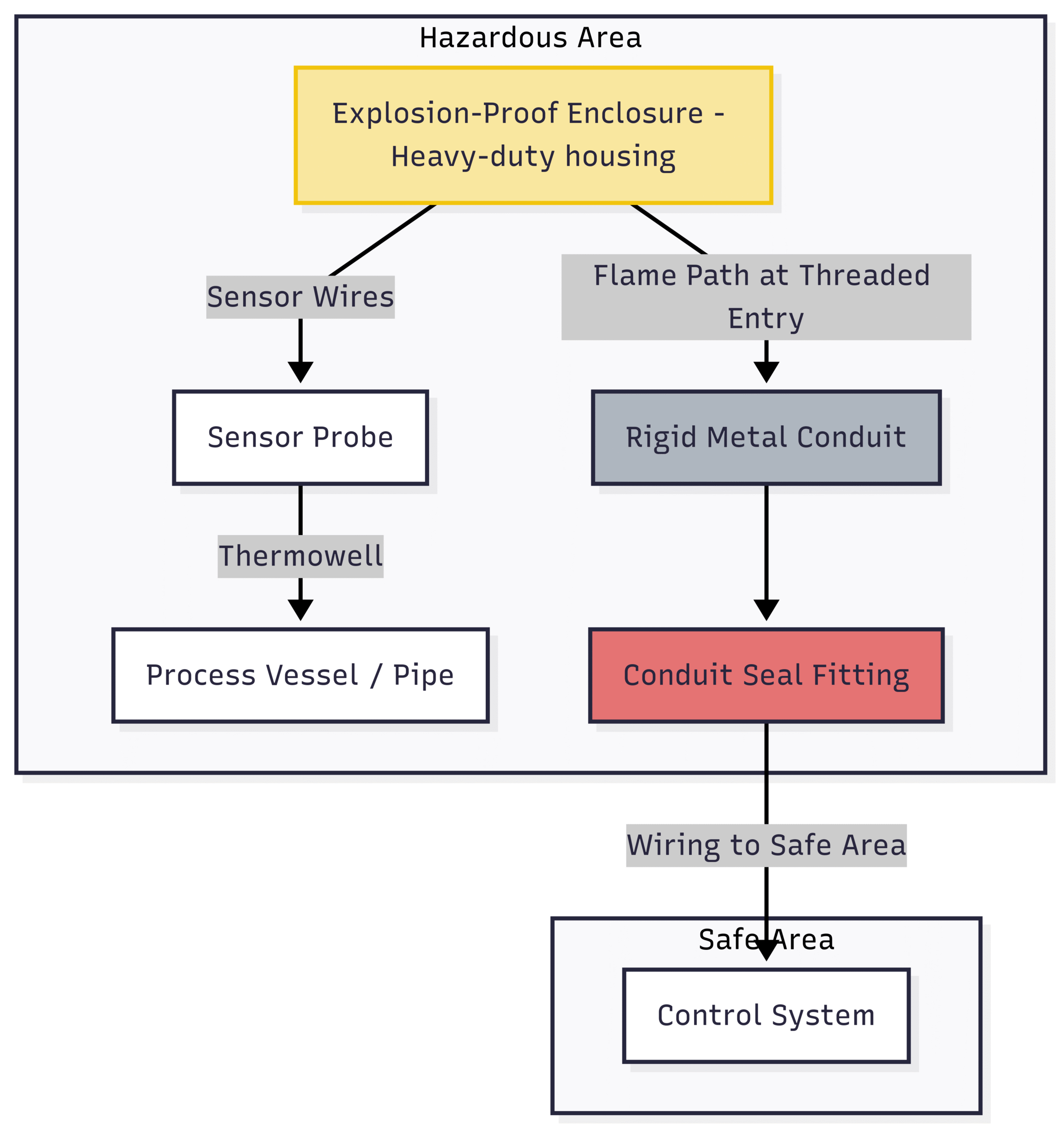
Explosion-Proof (a North American term) or Flameproof (an IEC/ATEX term) is a containment protection concept. This method does not prevent an explosion from occurring inside the equipment. Instead, it assumes an explosion will happen and is designed to contain it.
The concept relies on a highly robust enclosure, typically made of cast aluminum or stainless steel.
Containment: The enclosure is built to withstand the pressure of an internal explosion without rupturing.
Flame Path: The joints, flanges, and threaded entries of the enclosure are precisely engineered with small gaps (flame paths). If an internal explosion occurs, the hot expanding gases are forced through these long, narrow paths. As they travel, they are cooled to a temperature below the ignition point of the surrounding hazardous atmosphere, preventing the explosion from propagating outside the enclosure.
The temperature sensor probe itself extends from this enclosure into the process via a thermowell.
Advantages of Explosion-Proof:
Simplicity: Concept is easier to grasp than IS system calculations.
High Power: Can be used for higher-power devices.
Robustness: Enclosures are inherently very durable.
Disadvantages of Explosion-Proof:
Cost and Weight: Enclosures are heavy and expensive.
Installation Complexity: Requires rigid metal conduit and specialized sealing fittings to maintain the integrity of the flame path.
No Live Maintenance: The enclosure must be fully powered down before the cover is removed, as opening it compromises the protection.
Maintenance Intensive: The integrity of the flame path (flanges, threads) must be regularly inspected for scratches or corrosion.
Other Protection Methods
While IS and Ex d are the most common, other methods exist for specific situations, often in Zone 2 areas:
Increased Safety (Ex e): Prevents sparks and hot surfaces in normal operation. Often used for terminal boxes in conjunction with other methods.
Encapsulation (Ex m): Potential ignition sources are encased in a resin compound to prevent the hazardous atmosphere from reaching them.
Non-Incendive (NI) / Ex nA: A Zone 2 concept where equipment is non-sparking in normal operation.
The Installation Process: A Step-by-Step Guide
Proper installation is not just about connecting wires; it’s a procedural discipline that ensures the integrity of the chosen protection concept.
Step 1: Pre-Installation Planning and Documentation
Before a single tool is picked up, thorough planning is essential.
Review Area Classification: Obtain the official hazardous area classification drawing for the exact location.
Check Certifications: Verify that the sensor, thermowell, enclosure, barrier, and any other components have the correct ATEX/IECEx/etc. certification for the Zone, Gas/Dust Group, and Temperature Class (T-rating). The T-rating (T1 to T6) indicates the maximum surface temperature the equipment can reach, which must be lower than the auto-ignition temperature of the hazardous substance.
Gather Documentation: Have the manufacturer’s installation manuals for all components and the IS loop approval drawing (if applicable).
Obtain Permits: Secure all necessary work permits, such as a hot work permit or a safe work permit for hazardous areas.
Step 2: Mounting the Sensor and Thermowell
The thermowell is the first line of defense. It must be installed into the process pipe or vessel according to mechanical and piping specifications. Ensure the insertion length (‘U’ length) is correct to position the sensor tip in the ideal measurement location (typically the center third of the pipe).
Apply thread sealant that is appropriate for the process chemicals and pressure.
Once the thermowell is secure, insert the temperature sensor. Ensure the sensor makes good contact with the bottom of the thermowell for accurate heat transfer. Spring-loaded sensors are excellent for this.
Connect the sensor to its connection head or Ex d enclosure.
Step 3: Cabling, Glanding, and Conduit
This step is where the installation practices for Intrinsic Safety and Explosion-Proof diverge significantly.
For Intrinsic Safety (IS) Systems:
Cable Type: Use standard instrumentation cable. However, the cable’s capacitance () and inductance () per meter are critical.
Cable Segregation: IS cables must be physically separated from all non-IS cables. They should be run in separate trays or conduits.
Cable Color: IS cables are typically colored light blue to make them easily identifiable.
Glands: Standard industrial cable glands are usually sufficient, as the goal is not to contain an explosion.
System Calculation: The core requirement is to ensure the system is safe. The following conditions must be met:
(Barrier Output Voltage) ≥ (Sensor Input Voltage)
(Barrier Output Current) ≥ (Sensor Input Current)
(Barrier Output Power) ≥ (Sensor Input Power)
(Allowable Capacitance from Barrier) ≥ (Sensor Internal Capacitance) + (Total Cable Capacitance)
(Allowable Inductance from Barrier) ≥ L_{i} (Sensor Internal Inductance) + L_{cable} (Total Cable Inductance)
For Explosion-Proof (Ex d) Systems:
Cable Type: Armored cable is often used for mechanical protection.
Conduit: The primary wiring method is typically rigid metal conduit. This forms part of the flame path system.
Cable Glands: This is a critical component. A certified Ex d barrier gland must be used. This type of gland uses a potting compound or compression seal around the individual cable cores to prevent an explosion from traveling down the inside of the cable. Using a standard industrial gland completely invalidates the Ex d protection.
Conduit Seals: A sealing fitting (e.g., an “EYS” fitting) must be installed within 18 inches (45 cm) of the enclosure. This fitting is filled with a special sealing compound that hardens to create a solid plug, preventing explosive gases from passing through the conduit system from one area to another.
Step 4: Wiring and Terminations
Follow the manufacturer’s wiring diagram precisely. For a 3-wire RTD, ensure the compensating lead is correctly wired. For a thermocouple, pay strict attention to polarity. Reversing the positive and negative leads will result in incorrect readings.
Use the correct type of thermocouple extension wire, which must match the thermocouple type (e.g., Type K extension wire for a Type K thermocouple). Using copper wire will create an unwanted thermocouple junction, leading to large errors.
Ensure all terminal screws are tightened to the correct torque. A loose connection can cause arcing (a potential ignition source) or erratic readings.
Proper grounding/earthing is vital. For IS systems, the barrier’s ground connection is essential for safety. For Ex d systems, the enclosure must be bonded to the facility’s grounding system to prevent static buildup and ensure fault currents can flow safely.
Inspection, Maintenance, and Certification
Installation is not the end of the story. Safety is an ongoing process that requires regular inspection and maintenance.
Inspection Regimen
Inspections for hazardous area equipment are typically categorized into three levels (as per IEC 60079-17):
Visual Inspection: Can be done from a distance without opening enclosures. Check for obvious physical damage, corrosion, or missing bolts.
Close Inspection: A more detailed inspection within arm’s length. Check the integrity of gaskets, cable glands, and conduit entries. Verify that all bolts are present and tight.
Detailed Inspection: Requires the equipment to be de-energized and opened. Check internal terminals, the condition of flame paths (no scratches or damage), and verify all components match the certification documents.
A typical schedule might be: Visual inspection annually, close inspection every 2-3 years, and detailed inspection every 4-5 years, depending on environmental conditions and local regulations.
Key Maintenance Actions:
Calibration: Periodically remove the sensor (if a thermowell is used) and verify its accuracy against a calibrated reference.
Flame Path Integrity (Ex d): Never use abrasive tools or wire brushes on flame path surfaces. Clean them with a solvent and a soft cloth. Apply a thin, non-setting grease approved by the manufacturer to prevent corrosion.
Gasket Replacement: Replace enclosure gaskets if they are cracked or have lost their elasticity.
Documentation: Keep a detailed log of all inspections, maintenance actions, and calibrations for each hazardous area installation. This is a legal requirement in many jurisdictions.
Common Mistakes to Avoid ❌
Compromising safety in a hazardous area is not an option. Here are some of the most common—and dangerous—mistakes seen in the field:
Using Incorrect Cable Glands: Installing a standard industrial gland on an Ex d enclosure is a frequent and critical error. It completely negates the protection.
Damaging Flame Paths: Using a screwdriver to pry open an Ex d enclosure cover, scratching the flange faces. This creates a gap that can allow a flame to escape.
Mismatched Certifications: Installing a Zone 2 certified sensor in a Zone 1 area. The equipment must always be rated for the specific location.
Ignoring IS Loop Calculations: Failing to verify that the cable capacitance and inductance are within the barrier’s certified limits.
Incorrect Thermocouple Wiring: Using copper signal wire instead of the proper thermocouple extension wire.
Missing or Loose Bolts: Leaving a bolt out of an Ex d enclosure cover or not tightening them correctly compromises the containment seal.
Painting Over Labels or Flame Paths: Paint can obscure critical certification information and can interfere with the proper functioning of a flame path.
Conclusion: Safety by Design and Discipline
Installing a temperature sensor in a hazardous area is far more than a simple wiring task. It’s an engineering discipline that combines a thorough understanding of scientific principles with rigorous, procedural execution. From the initial area classification to the final torque of a terminal screw and the ongoing inspections years later, every step is critical to ensuring safety.
By prioritizing correct component selection, adhering strictly to the principles of the chosen protection concept (whether Intrinsic Safety or Explosion-Proof), and maintaining meticulous installation and maintenance practices, you ensure the integrity of your process. You protect your personnel, your plant, and the environment from the catastrophic potential of an explosion. In the world of hazardous areas, precision, compliance, and vigilance are the cornerstones of safety.