
Correct Mounting Techniques for Surface and Immersion Thermocouples
In the world of industrial processes, scientific research, and even everyday technology, accurate temperature measurement is not just a preference—it’s a necessity. From ensuring the safety of a chemical reactor to optimizing the efficiency of a furnace, precise temperature data is the bedrock of control and quality. At the heart of this measurement is a simple yet powerful device: the thermocouple.
However, the accuracy of a thermocouple reading doesn’t just depend on the quality of the sensor itself. How it’s installed—or mounted—can be the difference between a perfectly tuned process and a catastrophic failure. Improper mounting can introduce significant errors, leading to misleading data, inefficient operations, and potential safety hazards.
This comprehensive guide will delve into the critical, yet often overlooked, art and science of thermocouple mounting. We will explore the distinct challenges and best practices for both immersion thermocouples, used for measuring internal temperatures of fluids and solids, and surface thermocouples, designed to measure the temperature of a specific surface. By understanding the correct techniques, you can ensure your temperature measurements are reliable, repeatable, and truly representative of your process. Let’s unlock the full potential of these essential sensors.
Understanding Thermocouples: A Quick Refresher
Before we dive into mounting techniques, let’s quickly revisit what a thermocouple is and how it works. A thermocouple operates on a principle known as the Seebeck effect. This effect states that when two different types of electrical conductors (wires) are joined at two points and there is a temperature difference between these two junctions, a voltage is created.
Measuring Junction (Hot Junction): This is the end of the thermocouple that is placed at the point where you want to measure the temperature.
Reference Junction (Cold Junction): This is the end of the thermocouple that is connected to the measuring instrument.
The voltage produced is directly proportional to the temperature difference between these two junctions. The voltmeter or temperature controller measures this voltage, calculates the temperature difference based on the known characteristics of the thermocouple type (e.g., Type K, J, T), and then adds the known temperature of the reference junction to display the final temperature of the measuring junction.
Here’s a simple visualization of how a thermocouple circuit works:
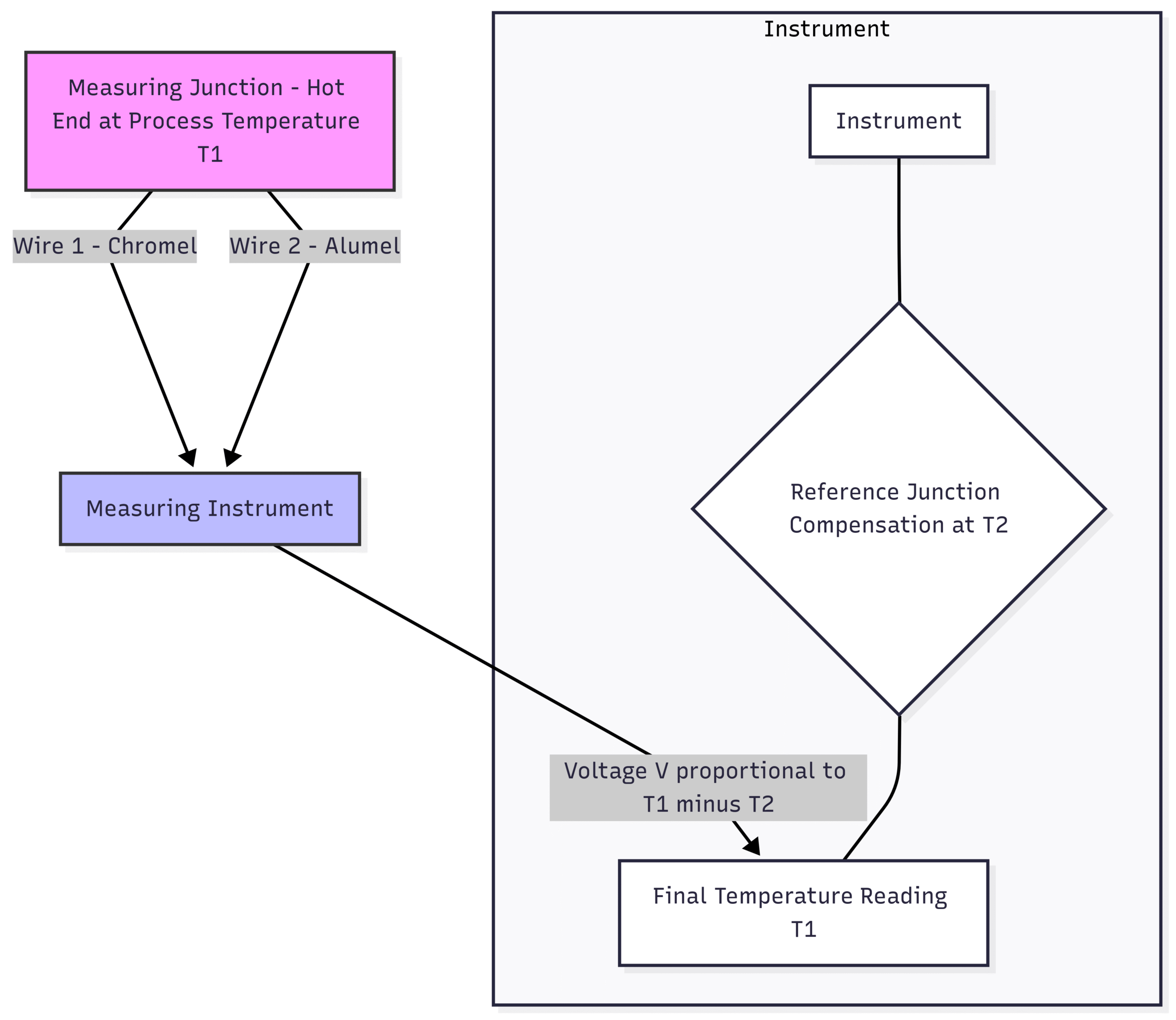
The simplicity of this design is what makes thermocouples so robust, versatile, and cost-effective. However, this simplicity also means that the data is highly susceptible to installation errors. The sensor will faithfully report the temperature at its tip. The goal of proper mounting is to ensure the temperature at the tip is the true temperature of the process you want to measure.
Correct Mounting Techniques for Immersion Thermocouples
Immersion thermocouples are designed to be inserted directly into the medium they are measuring, whether it’s a liquid, gas, or a solid material. They are the most common type used in pipes, tanks, furnaces, and vessels. The primary challenge with immersion mounting is ensuring the sensor reaches the actual process temperature without being unduly influenced by the external environment.
The Golden Rule: Sufficient Immersion Depth
The single most critical factor for accurate immersion measurement is immersion depth. If the thermocouple sheath is not inserted far enough into the process, a phenomenon called stem conduction or stem effect will occur. Heat will travel up or down the metal sheath of the thermocouple to or from the cooler or hotter external environment, causing the tip of the sensor to be at a different temperature than the surrounding medium.
Best Practice: The 10x Rule
A widely accepted rule of thumb is that the thermocouple should be immersed to a depth of at least 10 times the outer diameter of its sheath or thermowell. For example, if you are using a thermowell with a 1-inch outer diameter, the immersion length into the flowing medium should be a minimum of 10 inches. In many cases, especially with higher temperature differentials or low fluid velocity, an immersion of 15x or even 20x the diameter is recommended for higher accuracy.
Placement in Pipes:
When measuring the temperature of a fluid in a pipe, the tip of the thermocouple should ideally be placed in the center third of the pipe’s diameter. This is typically where the flow is most stable and the temperature is most representative of the bulk fluid.
Against the Flow: The thermocouple should be installed so that the fluid flows against the sensing tip. This improves the heat transfer rate to the sensor.
Elbows and Bends: Installing a thermocouple at an elbow or bend is often ideal. The turbulence in these areas promotes better mixing of the fluid, leading to a more uniform temperature profile and a more accurate reading. The sensor should be installed facing into the flow.
Mounting Hardware: Thermowells, Fittings, and Flanges
You rarely insert a bare thermocouple directly into an industrial process. Instead, you use specialized hardware that protects the sensor and facilitates easy replacement.
1. Thermowells
A thermowell is a permanent, pressure-tight receptacle that is installed into a process vessel or pipe. The thermocouple is then inserted into the thermowell.
Advantages of a Thermowell:
Protection: It shields the thermocouple from corrosive chemicals, physical impact, high pressure, and high-velocity fluids.
Maintenance: The thermocouple can be removed and replaced for calibration or servicing without shutting down or draining the process. This is a massive advantage in continuous operations.
Longevity: It extends the life of the thermocouple sensor significantly.
Mounting a Thermowell: Thermowells can be threaded, welded (socket weld or butt weld), or flanged. The choice depends on the pressure, temperature, and nature of the process.
Threaded Thermowells: These are screwed into a threaded port (a “threadolet”) on the pipe or vessel. They are common in lower-pressure applications. Use of a suitable thread sealant (like PTFE tape or pipe dope rated for the process conditions) is crucial to prevent leaks.
Weld-in Thermowells: These are welded directly to the pipe or vessel, providing a very strong and permanent seal suitable for high-pressure and high-temperature applications. This installation requires a certified welder.
Flanged Thermowells: These have a flange that bolts to a corresponding flange on the process piping. They are used in applications where pipes are frequently disassembled or in very large piping systems.
The following diagram illustrates a proper thermowell installation in a pipe:
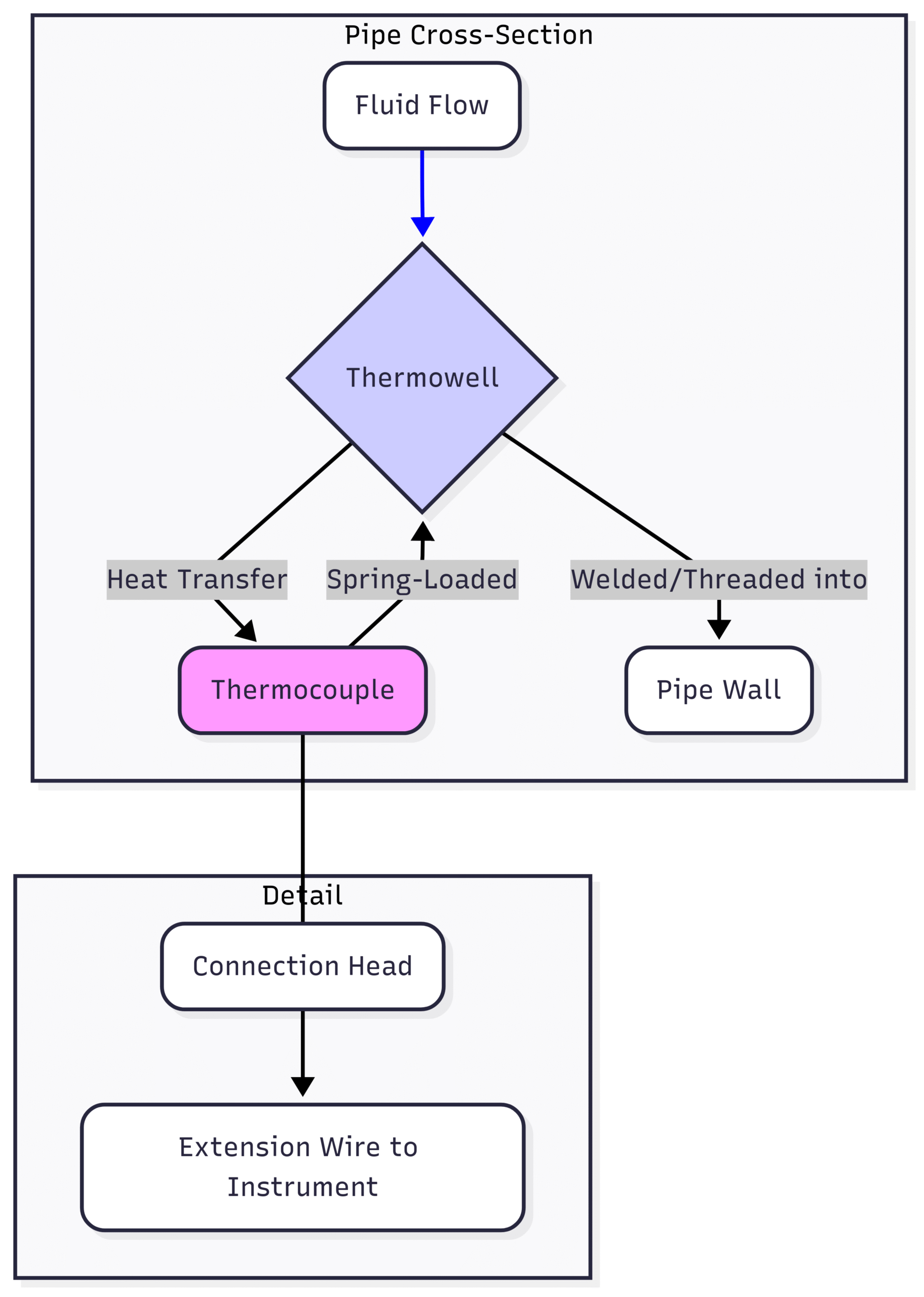
Key Installation Tip: To ensure good thermal transfer from the thermowell to the thermocouple, the thermocouple should be a snug fit inside the thermowell bore. For optimal performance, a spring-loaded thermocouple is highly recommended. The spring pushes the tip of the thermocouple firmly against the bottom of the thermowell bore, guaranteeing excellent metal-to-metal contact and minimizing thermal lag.
2. Compression Fittings
For applications where a thermowell isn’t necessary (e.g., lower pressure, non-corrosive environments, or laboratory setups), a compression fitting can be used. This fitting consists of a body, a nut, and one or two ferrules. As the nut is tightened, the ferrule(s) compress onto the thermocouple sheath, creating a seal.
Advantages of Compression Fittings:
Adjustability: They allow for adjustable immersion depth. You can slide the thermocouple in or out to the desired position before tightening.
Simplicity: They are easy and quick to install.
Installation Tip: Be careful not to over-tighten a compression fitting, as this can crush or damage the thermocouple sheath and the delicate wires inside. Tighten just enough to secure the probe and create a seal.
Correct Mounting Techniques for Surface Thermocouples
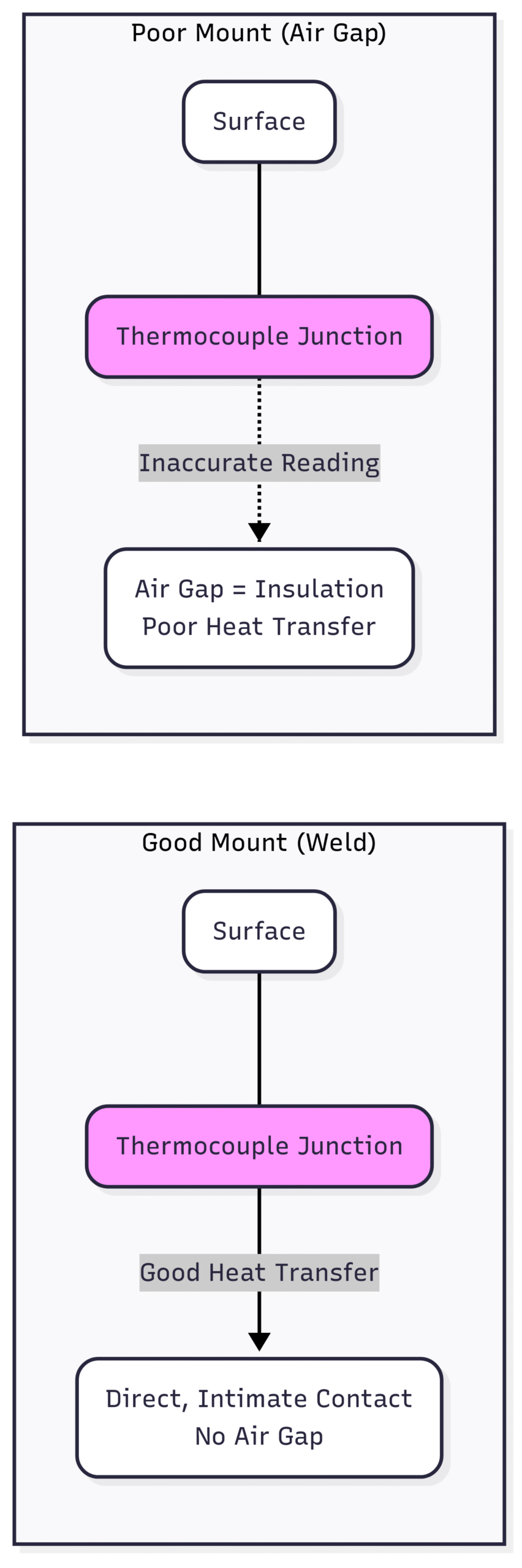
Measuring the temperature of a surface presents a completely different set of challenges. Unlike an immersion sensor which is surrounded by the medium, a surface sensor is only in contact on one side. The other sides are exposed to the ambient air, which can wick heat away from the sensor and cause a significantly low reading. The goal of surface mounting is to maximize thermal contact with the surface and minimize heat loss to the surroundings.
The Challenge: Thermal Contact and Heat Loss
An accurate surface reading is only possible if the thermocouple junction reaches thermal equilibrium with the surface. Any air gap, no matter how small, acts as an insulator and will disrupt this heat transfer. Furthermore, the sensor and its mounting hardware create a path for heat to escape to the cooler ambient air, a form of stem conduction error applied to a surface.
Methods for Mounting Surface Thermocouples
The best method depends on the surface material, the temperature range, and whether the installation needs to be permanent or temporary.
1. Welding
For permanent installations on metallic surfaces, welding is the gold standard. It provides the most direct, robust, and reliable thermal connection. A small bead weld can be used to attach the thermocouple junction directly to the surface.
Best Practice: Capacitive Discharge Welding Capacitive discharge (CD) welders are ideal for attaching thermocouples. They deliver a very brief, high-energy pulse that creates a clean weld without introducing significant heat into the surrounding area, which could alter the material’s properties or damage the sensor.
Diagram: Good vs. Poor Surface Mounting This diagram shows the difference between a direct weld and a poorly attached sensor, highlighting the insulating air gap.
When welding is not feasible (e.g., on sensitive components, temporary setups, or for non-weldable materials), clamps are an excellent alternative. Pipe clamps or hose clamps can be used to firmly press a thermocouple probe or pad against a pipe or other curved surface.
Best Practice:
Use a Heat Transfer Compound: Before clamping, apply a small amount of thermal paste or grease (like silicone-based heat sink compound) to the contact point. This paste fills in the microscopic air gaps between the sensor and the surface, dramatically improving thermal conductivity.
Ensure High Clamping Force: The clamp must be tight enough to ensure firm, continuous pressure.
3. Adhesives and Cements
For flat surfaces or areas where clamps won’t work, specialized adhesives can be used.
Epoxies: High-temperature thermal epoxies can create a permanent, strong bond with good thermal conductivity. Ensure the epoxy’s temperature rating exceeds your maximum process temperature.
Ceramic Cements: For very high-temperature applications (above the range of epoxies), ceramic cements are used. They are applied as a paste and then cured (often by heating) to form a hard, thermally conductive bond.
Adhesive Pads: Some thermocouples come with a pre-applied adhesive patch made of materials like Kapton or aluminum foil. These are extremely convenient for quick, temporary installations on clean, smooth surfaces.
4. Magnetic Mounts
For quick, temporary measurements on ferrous metal surfaces (iron, steel), magnetic thermocouples are incredibly useful. They have a powerful magnet that holds the sensor tip firmly against the surface. While convenient, they are generally less accurate than a permanent mount like a weld because achieving perfect contact can be difficult. They are best suited for diagnostic checks rather than precision process control.
Minimizing Heat Loss: The Role of Insulation
Regardless of the mounting method, you must address heat loss to the ambient air. Once the thermocouple is mounted, cover the sensor and a few inches of its lead wire with an insulating pad. This pad prevents the cooler ambient air from convection-cooling the measurement site. Materials like ceramic fiber or high-temperature fiberglass insulation are commonly used. This step is absolutely critical for achieving high accuracy in surface temperature measurement.
Common Mistakes to Avoid
Even with the right hardware, simple mistakes can ruin your measurements. Here are some common pitfalls to watch out for:
Insufficient Immersion Depth: The most common error with immersion probes. Always follow the 10x rule as a minimum.
Poor Thermal Contact: For surface mounts, failing to use thermal paste or not ensuring a tight clamp will lead to low readings. For immersion probes, using a non-spring-loaded probe in a loose-fitting thermowell will cause slow response and inaccuracy.
Ground Loops: If a thermocouple’s sheath touches a grounded point in the process, and the measurement instrument is also grounded elsewhere, a “ground loop” can form. This creates electrical noise that interferes with the tiny thermocouple voltage signal. Use ungrounded thermocouples or isolated measurement instruments to prevent this.
RFI/EMI Interference: Thermocouple wires can act as antennas, picking up electromagnetic interference (EMI) from motors, power lines, or radio frequency interference (RFI) from two-way radios. Use shielded extension wire and proper grounding of the shield (at the instrument end only) to minimize this noise.
Using the Wrong Extension Wire: Always use the correct type of thermocouple extension wire to connect the probe to the instrument (e.g., Type K wire for a Type K thermocouple). Using ordinary copper wire will create a new thermocouple junction at the connection point, introducing a significant error.
Conclusion
A thermocouple is a beautifully simple device, but its simplicity belies the importance of its installation. Correct mounting is not an optional finishing touch; it is a fundamental requirement for accurate and reliable temperature measurement.
For immersion thermocouples, the key is to achieve sufficient immersion depth to overcome the stem effect, often by using a properly installed thermowell and a spring-loaded sensor.
For surface thermocouples, the focus is on maximizing thermal contact through methods like welding or clamping with thermal paste, and minimizing heat loss by covering the area with insulation.
By avoiding common mistakes and applying the techniques outlined in this guide, you can transform your thermocouple from a simple sensor into a precision instrument. Taking the time to mount your thermocouples correctly will pay dividends in process efficiency, product quality, and operational safety, ensuring that the data you collect is a true reflection of reality.