
Digital vs. Analog I/O: Key Differences in PLC Systems
In the world of industrial automation, Programmable Logic Controllers (PLCs) are the brains of the operation. They control everything from simple machine sequences to complex manufacturing processes. But for a PLC to control anything, it needs to interact with the real world. It does this through its Input/Output (I/O) system. This system is the crucial bridge between the PLC’s digital brain and the physical devices on the factory floor. 🤖
The I/O system is divided into two fundamental categories: Digital and Analog. Understanding the difference between these two isn’t just academic; it’s essential for designing, programming, and troubleshooting any automated system. Choosing the wrong type of I/O can lead to system malfunctions, inaccurate control, and costly downtime.
This comprehensive guide will dive deep into the world of PLC I/O. We’ll explore the core concepts of digital and analog signals, break down their key differences, examine real-world applications, and help you understand how to select the right I/O for your specific needs.
What is Digital I/O? The World of ON/OFF
Digital I/O, often called Discrete I/O, is the simplest and most common type of interface in PLC systems. The word “digital” here refers to the binary nature of the signals. A digital signal can only exist in one of two distinct states: ON or OFF. Think of a standard light switch—it’s either on or it’s off. There’s no in-between.
In the context of a PLC, these two states are represented by specific voltage or current levels.
ON State: A specific voltage is present (e.g., 24V DC or 120V AC). This is often interpreted as a logical ‘1’ or ‘TRUE’.
OFF State: There is an absence of voltage (or a voltage close to 0V). This is interpreted as a logical ‘0’ or ‘FALSE’.
This binary, yes-or-no nature makes digital I/O perfect for monitoring and controlling devices that have a limited number of conditions.
Digital Input Devices (Sensors)
Digital input modules connect the PLC to devices that provide a binary signal. The PLC “reads” the state of these devices to understand what’s happening in the process. Common digital input devices include:
Pushbuttons and Switches: The most basic examples. Is the button pressed? Is the switch open or closed?
Proximity Sensors: These detect the presence or absence of an object without physical contact. They send an ON signal when an object is within their sensing range.
Photoelectric Sensors: Use a beam of light to detect objects. When an object breaks the beam, the sensor’s state changes.
Limit Switches: Mechanical switches that are activated by the motion of a machine part. For example, a limit switch can signal that a safety gate is closed.
Level Switches: Detect if the level of a liquid in a tank is above or below a certain point (e.g., high-level alarm).
Digital Output Devices (Actuators)
Digital output modules allow the PLC to control devices by turning them ON or OFF. The PLC sends a voltage signal to an output device to energize or de-energize it. Common digital output devices include:
Indicator Lights and Alarms: The PLC can turn on a green light to indicate normal operation or a red flashing alarm during a fault.
Relays and Contactors: A PLC output can energize the coil of a relay or contactor, which in turn can switch a much higher voltage or current to control powerful devices like large motors or heating elements.
Solenoid Valves: Used to control the flow of air (pneumatics) or fluid (hydraulics). The PLC can energize a solenoid to open a valve and de-energize it to close it.
Small Motors: Simple ON/OFF control for motors used in applications like conveyor belts.
How Digital I/O Works: A Simple Circuit
Let’s visualize a basic digital I/O circuit. A pushbutton (input) tells the PLC to turn on an indicator light (output).
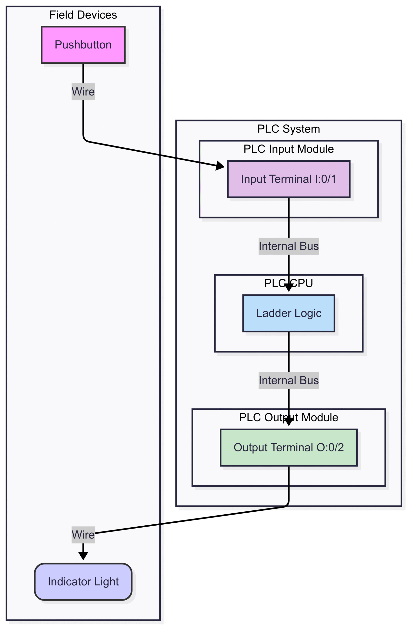
When the Pushbutton (PB) is pressed, it completes a circuit, sending a 24V DC signal to the PLC’s Input Terminal (I1).
The input module detects this voltage and updates the PLC’s memory, setting the bit associated with I1 to ‘1’.
The PLC CPU continuously scans its program (Ladder Logic). The logic shown says, “If the input I1 is ON, then turn the output O1 ON.”
The CPU sends a command to the Output Module to energize the Output Terminal (O1).
The output module sends 24V DC to the Indicator Light, causing it to turn on.
Sinking vs. Sourcing I/O
A key concept in digital DC circuits is sinking and sourcing. This determines the direction of conventional current flow between the I/O module and the field device.
Sourcing: The I/O module provides the power. Current flows out of the module, through the field device, and then to ground (0V). Sourcing modules are often used with sinking sensors/actuators.
Sinking: The I/O module receives the power. Current flows from a power supply, through the field device, and then into the I/O module to ground. Sinking modules are used with sourcing sensors/actuators.
It’s critical to match the type of module with the type of field device to ensure they work together correctly. Mixing them up will result in a non-functional circuit.
What is Analog I/O? The World of Infinite Variability
While digital signals are black and white, analog signals are full color. 🌈 Analog I/O deals with signals that can vary continuously over a specified range. Instead of just ON or OFF, an analog signal can represent any value within its limits.
Think of a dimmer switch for a light. You can slide it to make the light just a little bright, very bright, or any level in between. This continuous variability is the hallmark of an analog signal.
In industrial automation, analog signals are essential for measuring and controlling processes that require precision and finesse. These measurements are not simple yes/no questions; they answer “how much?”.
How hot is the oven?
How fast is the motor spinning?
What is the pressure in the pipe?
How much liquid is in the tank?
Analog Input Devices (Transmitters/Sensors)
Analog input modules measure the continuous signal from a sensor and convert it into a digital value that the PLC’s processor can understand. This conversion is done by an Analog-to-Digital Converter (ADC).
The signals from these sensors are typically represented as a range of voltage or current. The most common industrial standards are:
Voltage: 0-10V DC, 0-5V DC
Current: 4-20mA (milliamps)
The 4-20mA signal is particularly popular in industry. Why? It offers a key advantage called “live zero.” Since the lowest signal is 4mA, not 0mA, a reading of 0mA indicates a problem, like a broken wire or a failed sensor. This makes troubleshooting much easier.
Common analog input devices include:
Temperature Sensors: Thermocouples and RTDs (Resistance Temperature Detectors) measure temperature and, with a transmitter, output a proportional 4-20mA or 0-10V signal.
Pressure Transmitters: Measure the pressure of a liquid or gas in a vessel or pipe.
Flow Meters: Measure the rate at which a fluid is moving through a pipe.
Level Transmitters: Provide a continuous measurement of the liquid level in a tank, unlike a simple high/low level switch.
Potentiometers: Used to measure rotational position, like the angle of a valve.
Analog Output Devices (Actuators)
Analog output modules take a digital value from the PLC’s CPU and convert it into a variable voltage or current signal to precisely control a device. This is handled by a Digital-to-Analog Converter (DAC).
Common analog output devices include:
Variable Frequency Drives (VFDs): A VFD controls the speed of an AC motor. A PLC can send a 0-10V or 4-20mA signal to the VFD to tell it how fast the motor should run. For example, 0V might be 0 RPM, and 10V might be the motor’s maximum speed (e.g., 1800 RPM).
Proportional Valves: Unlike ON/OFF solenoid valves, these valves can be opened to any position to precisely control the flow rate of a fluid. A 4mA signal might keep the valve closed, while a 20mA signal opens it fully, and 12mA opens it to 50%.
Actuators: Devices that can move to a specific position based on the analog signal.
Heaters: The output to a heating element can be varied to maintain a precise temperature.
How Analog I/O Works: Resolution and Scaling
Let’s imagine a PLC is controlling the speed of a motor using a VFD. The PLC’s analog output is a 0-10V signal, which corresponds to a motor speed of 0-1500 RPM.
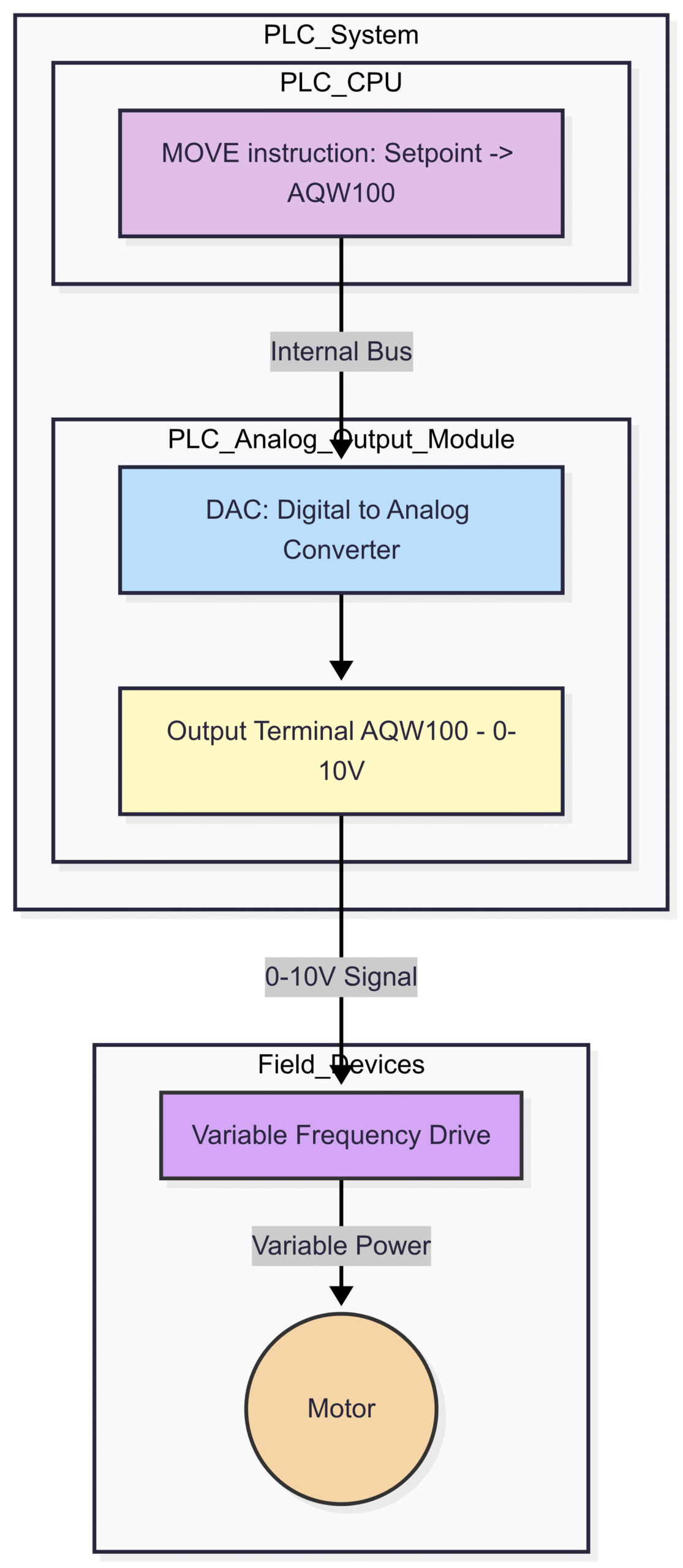
In this process:The PLC Program determines the desired speed (e.g., 750 RPM). This is the Setpoint.
The program then scales this value into a corresponding digital number for the output module.
The DAC in the analog output module converts this digital number into a specific voltage. Since 750 RPM is 50% of the 1500 RPM max speed, the DAC outputs a 5V signal (50% of 10V).
This 5V signal is sent to the VFD.
The VFD interprets the 5V signal and adjusts the frequency of the power it sends to the Motor, causing it to run at 750 RPM.
A critical concept here is resolution. The resolution of an analog module determines how many discrete steps it can use to represent the analog range. It’s usually specified in bits. A 12-bit module, for example, can represent the signal in steps. A 16-bit module offers much higher precision with steps. Higher resolution means finer control and more accurate measurements.
Head-to-Head Comparison: Digital vs. Analog I/O
Now that we’ve covered the basics of both, let’s put them side-by-side to highlight their key differences. 🥊
Choosing the Right I/O for Your Application
The decision to use digital or analog I/O is driven entirely by the application. There’s no “better” type—only the “right” type for the job. Here’s a simple thought process for making the choice:
1. Analyze the Input Signal:
Question: What information do I need from this sensor?
If the answer is a simple state: Is the door closed? Is the part in position? Is the tank full? -> Use Digital Input.
If the answer is a measurement: What is the exact temperature? What is the flow rate? What is the tank level? -> Use Analog Input.
2. Analyze the Required Output Control:
Question: How do I need to control this device?
If the control is simple ON/OFF: Start the conveyor, open the main valve, turn on the alarm. -> Use Digital Output.
If the control requires precision or variability: Adjust the motor speed, maintain a specific temperature, position a valve to 30% open. -> Use Analog Output.
Hybrid Scenarios: Using Both Together
Most real-world automation systems are not purely digital or purely analog. They are a sophisticated mix of both, working in harmony.
Consider a batch mixing process in a tank:
Digital Inputs: Proximity sensor to confirm the tank is in place, level switches for high and low alarms.
Digital Outputs: Solenoid valves to add ingredients, a mixer motor (ON/OFF), an indicator light for “Process Complete”.
Analog Inputs: A level transmitter to continuously monitor the volume, a temperature transmitter to monitor the mix temperature.
Analog Outputs: A proportional valve to control the flow of steam into a heating jacket, a VFD on the mixer motor to vary the mixing speed.
In this system, the PLC uses digital inputs to ensure safety and proper sequencing, while using analog I/O to precisely control the critical process variables of temperature, level, and speed. The PLC might read the analog temperature input and use a PID (Proportional-Integral-Derivative) control loop to calculate the exact analog output needed for the steam valve to maintain the perfect temperature. This level of sophisticated control is only possible by combining the strengths of both digital and analog I/O.
Conclusion: The Language of Automation
Understanding the difference between digital and analog I/O is fundamental to mastering PLC systems and industrial automation. Digital I/O provides the simple, robust, yes-or-no language for sequencing and state-based control. Analog I/O offers the nuanced, precise language needed for fine control and measurement of the physical world.
Digital I/O is for discrete control—the “what” and “if.”
Analog I/O is for process control—the “how much.”
A well-designed automated system leverages the strengths of both. By correctly identifying the needs of each sensor and actuator in your process and selecting the appropriate I/O modules, you create a system that is efficient, reliable, and capable of the precise control needed to produce high-quality products. The next time you see a complex machine operating seamlessly, you can be sure that behind the scenes, a PLC is expertly interpreting a symphony of digital and analog signals to make it all happen. ⚙️📈