
The Role of the CPU in DCS Processing Power: A Deep Dive
In the intricate and high-stakes world of industrial automation, the Distributed Control System (DCS) stands as the undisputed brain and central nervous system. It orchestrates thousands of simultaneous operations, from refining crude oil to manufacturing life-saving pharmaceuticals. But what powers this industrial brain? At its very core lies the Central Processing Unit (CPU), a component whose capabilities directly define the performance, reliability, and safety of the entire plant.
Understanding the role of the CPU in a DCS is not just an academic exercise for IT specialists; it’s a critical piece of knowledge for any process engineer, automation professional, or plant manager. The choice of processing power impacts everything from the tightness of control loops and production throughput to the system’s ability to handle upsets and expand for future needs.
This comprehensive guide will explore the pivotal role of the CPU in DCS processing power. We’ll dissect its core functions, examine the specifications that truly matter, and provide a framework for understanding how to ensure your control system has the computational muscle it needs to excel.
What is a Distributed Control System (DCS)?
Before we zoom in on the CPU, let’s first establish its environment. A DCS is a specialized control system for a process or plant, in which control elements are not centralized in one location but are distributed throughout the system. This distribution is key to its reliability and scalability.
Unlike a Programmable Logic Controller (PLC), which is often used for smaller, discrete control tasks, a DCS is designed for large-scale, continuous process control. It integrates process loops, advanced control strategies, system security, and a common operator interface (HMI) into a single, cohesive ecosystem.
A typical DCS architecture consists of several key layers:
Level 0 (Field Level): Contains the field devices like sensors (measuring temperature, pressure, flow) and actuators (valves, motors).
Level 1 (Control Level): This is where the magic happens. It consists of distributed controllers or process stations, each containing one or more CPUs. These controllers execute the control logic for a specific area of the plant.
Level 2 (Supervisory Level): This includes the operator stations (HMIs), where operators monitor and interact with the process, and engineering workstations, used for configuration and maintenance. It also includes historical data servers.
Level 3 & 4 (Planning and Management): These levels connect the plant floor to the enterprise business systems (ERP).
The CPU we are discussing resides primarily in the controllers at Level 1. It is the engine that executes the automation strategy programmed by engineers and commanded by operators.
Here’s a simplified view of a typical DCS architecture:
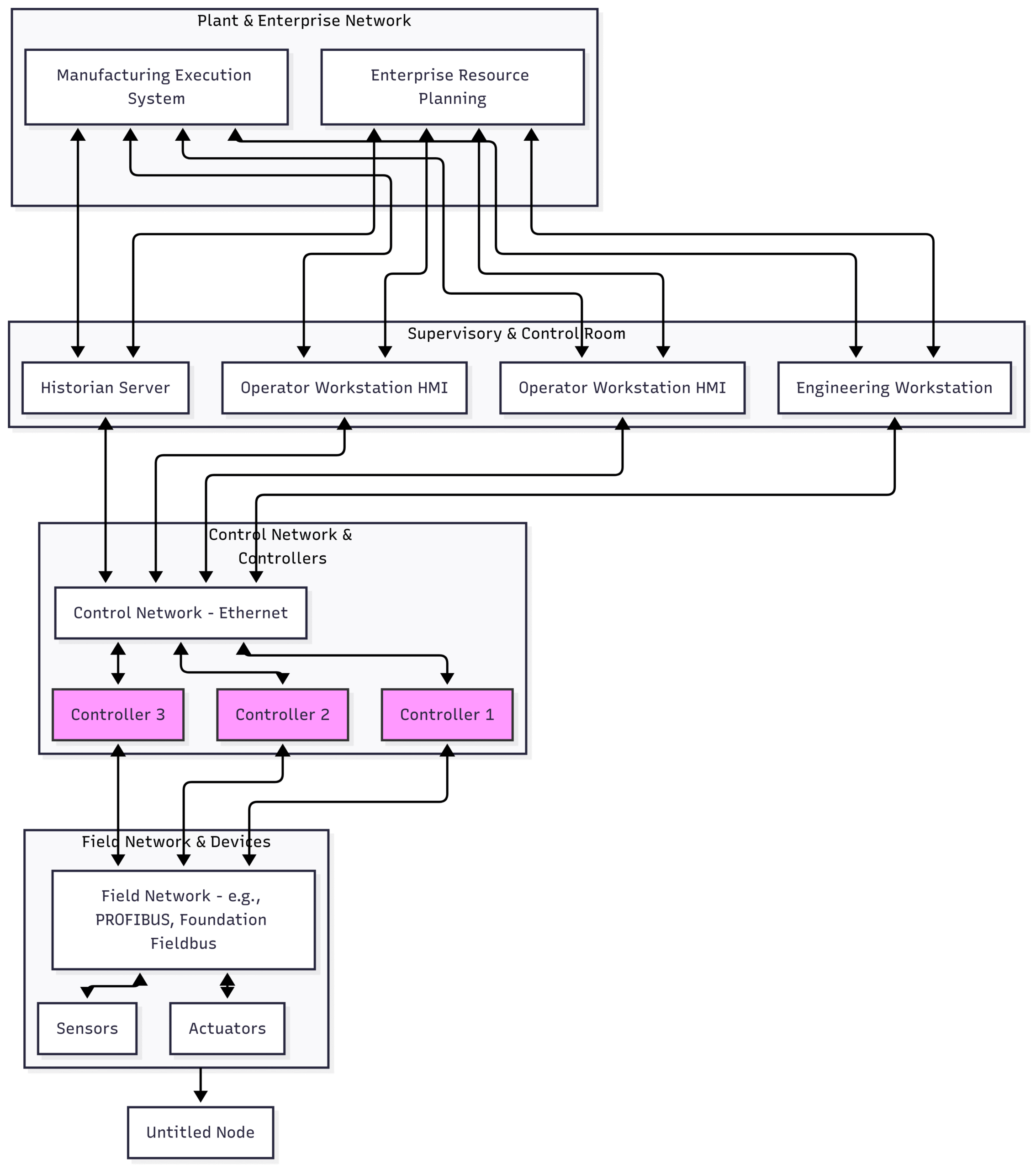
In this architecture, the critical CPUs reside within Controllers 1, 2, and 3, executing the real-time process control.
The CPU’s Mandate:
The CPU in a general-purpose computer (like a desktop PC) is a jack-of-all-trades, juggling web Browse, spreadsheets, and video streaming. A DCS CPU, however, is a highly specialized master of a few critical domains. Its primary mandate is determinism—the ability to execute a specific set of tasks predictably and on time, every single time, with no exceptions. A missed deadline in an office application is an inconvenience; a missed deadline in a chemical reactor’s control loop could be catastrophic.
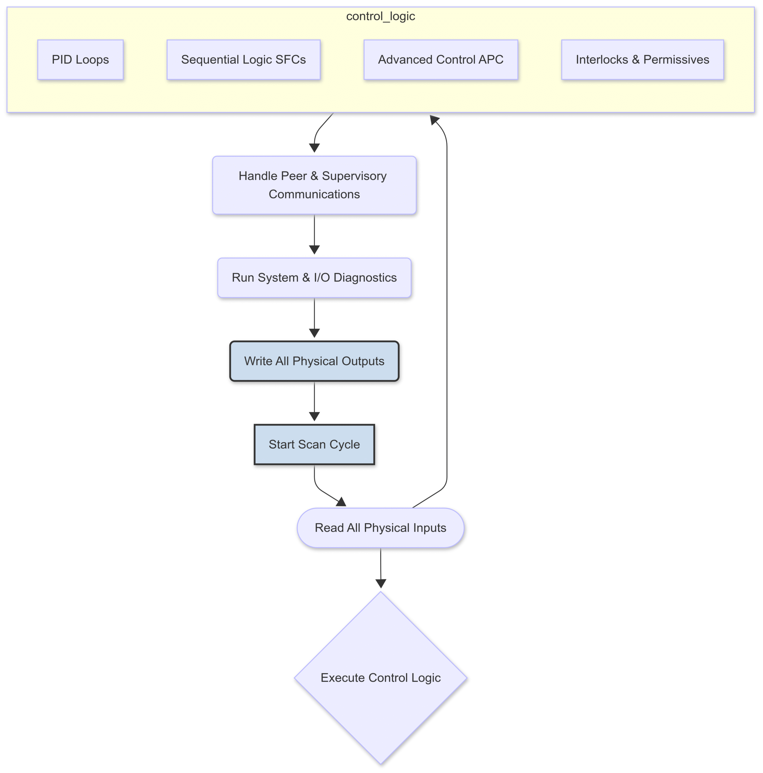
The CPU’s workload can be broken down into four main responsibilities, which are typically executed in a continuous loop known as the scan cycle.
1. Real-Time Control Loop Execution
This is the CPU’s most important job. It involves continuously solving the mathematical equations that govern the process. The most common of these is the Proportional-Integral-Derivative (PID) control algorithm.
The classic PID algorithm is represented as:
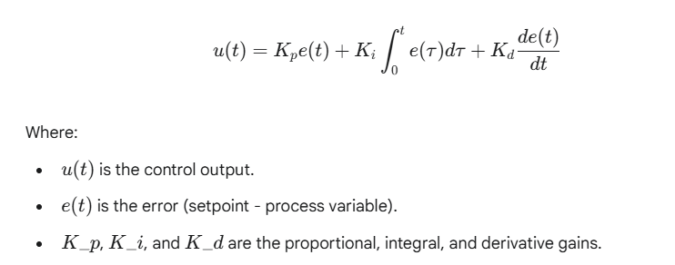
The CPU must calculate this, and often thousands of other simple and complex algorithms, during each scan. The time it takes to complete one full cycle of reading inputs, executing all logic, and writing outputs is the scan time or cycle time. A more powerful CPU can execute more logic in less time, enabling a faster scan cycle. This is critical for processes that change rapidly, as it allows the controller to react more quickly to disturbances, resulting in tighter control, higher product quality, and improved stability.
2. I/O Processing and Communication
A modern DCS controller can be connected to thousands of individual I/O points. The CPU is responsible for:
Reading Inputs: Systematically collecting data from all connected sensors via I/O modules.
Writing Outputs: Sending command signals to all connected actuators.
Managing Fieldbus Protocols: Handling the complex communication and timing requirements of digital fieldbuses like Foundation Fieldbus, PROFIBUS, or HART. This isn’t just data transfer; it involves scheduling, diagnostics, and parameterization of smart devices in the field.
3. Supervisory and Advanced Process Control (APC)
Beyond basic loops, the CPU executes higher-level logic:
Interlocking: Safety logic that prevents dangerous conditions (e.g., preventing a valve from opening unless a pump is running).
Sequential Function Charts (SFCs): Step-by-step logic used for batch processes or startup/shutdown sequences.
Advanced Process Control (APC): These are computationally intensive models, such as Model Predictive Control (MPC), that predict how a process will behave in the future and optimize multiple variables simultaneously. Running APC requires significant floating-point calculation power.
4. System Diagnostics and Redundancy Management
Reliability is paramount. The DCS CPU is constantly performing self-checks on its own hardware, its memory, its power supply, and its communication links. In a redundant controller pair (a primary and a backup), the CPUs are in constant communication. They must flawlessly manage the health status of each other so that if the primary CPU fails, the backup can take over control in a single scan cycle without any disruption to the process—a procedure known as a bumpless transfer.
This diagram illustrates the CPU’s tasks within a single, continuous scan cycle:
Decoding the Specs: What Matters in a DCS CPU?
When looking at a CPU’s specifications, it’s easy to get lost in a sea of numbers. For a DCS application, some metrics are far more important than others.
Clock Speed vs. IPC (Instructions Per Cycle)
For years, clock speed (measured in Gigahertz, GHz) was the primary marketing metric for CPU performance. While a higher clock speed means the CPU’s internal clock is ticking faster, it doesn’t tell the whole story. A more crucial metric is IPC (Instructions Per Cycle), which measures how much actual work the CPU can accomplish in each clock tick.
Modern CPU architectures have dramatically improved IPC. This means a newer 3.0 GHz CPU can often outperform an older 4.0 GHz CPU because it accomplishes more with each cycle.
Analogy: Think of two factory workers. Worker A can move their hands very fast (high clock speed), but can only carry one box at a time. Worker B moves their hands slightly slower (lower clock speed) but can carry four boxes at once (high IPC). Worker B will get the job done much faster.
For DCS applications, a balance is key, but improvements in IPC and architecture from reputable manufacturers (like Intel or AMD, whose processors are often the basis for DCS controllers) are generally more impactful than raw clock speed alone.
The Multi-Core Revolution in Industrial Control
Perhaps the single most important advancement in CPU technology for DCS has been the move to multi-core processors. Instead of one powerful processing core, a CPU now has two, four, or even more cores on a single chip. This is a perfect match for the multitasking nature of a DCS controller.
DCS vendors don’t just use these cores to run things faster in parallel as a desktop PC might. They use a sophisticated strategy called core allocation or core affinity to enhance determinism and reliability. A core is dedicated to performing a specific type of task, preventing lower-priority tasks from interfering with high-priority ones.
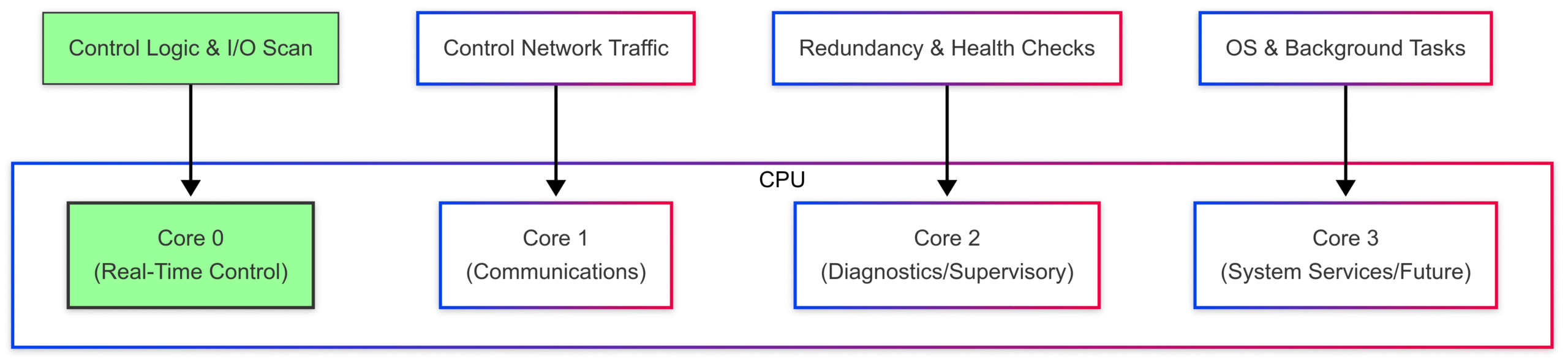
A typical allocation strategy might look like this:
Core 0 (The Real-Time Core): This core is exclusively dedicated to the highest priority task: executing the deterministic control loops (PID, etc.). No other operating system tasks or communication processes are allowed to run on this core. This guarantees the scan time is predictable.
Core 1 (Communications Core): This core handles all network traffic—communicating with operator stations, the engineering workstation, and peer controllers. This offloads the heavy work of network packet processing from the control core.
Core 2 (Supervisory & Diagnostics Core): This core runs lower-priority background tasks, such as complex diagnostics, managing redundancy, and executing non-critical supervisory logic.
Core 3 (Utility/Future Core): This core might be reserved for system services, future applications like integrated AI analytics, or simply left as overhead to ensure the system is never strained.
This partitioning is a cornerstone of modern DCS design, providing both high performance and rock-solid determinism.
Cache Size and Memory Management
Cache is a small amount of super-fast memory located directly on the CPU chip. It stores frequently used data and instructions, so the CPU doesn’t have to wait for the much slower main system memory (RAM).
L1 Cache: Smallest and fastest, dedicated to a single core.
L2 Cache: Larger and slightly slower, often also dedicated to a single core.
L3 Cache: Largest and slowest of the three, but still incredibly fast compared to RAM. It is typically shared among all cores.
For a DCS, a large and efficient cache is vital. When the CPU executes the same control loops over and over again every few milliseconds, the ability to keep that logic in the L1 or L2 cache dramatically reduces latency and helps maintain a consistent, deterministic scan time.
Future-Proofing Your Plant: Choosing the Right Processing Power
You don’t buy a DCS CPU off the shelf at a computer store. You select a controller platform from a DCS vendor (like Emerson, Honeywell, Siemens, ABB, or Yokogawa) that has a specific, validated CPU at its heart. The key is to choose a platform with the right amount of processing power for your needs—both today and tomorrow.
Analyzing Your Process Requirements
Sizing a controller’s CPU requires a thorough analysis of the application:
I/O Count: How many sensors and actuators will this controller manage? More I/O means more processing overhead.
Loop Count and Complexity: Is it 100 simple PID loops or 20 complex, cascaded loops with advanced algorithms?
Required Scan Time: A fast chemical reaction may require a 50ms scan time, while a slow tank level control might be fine with a 500ms scan. Faster scan times demand more CPU power.
Communication Load: Will the controller be communicating extensively with other systems, PLCs, or enterprise networks?
APC & Advanced Logic: The use of computationally heavy APC or complex sequential logic significantly increases CPU demand.
The Concept of “CPU Load”
DCS vendors provide engineering tools that can estimate the projected CPU load based on the configuration. This “load” is a percentage of the CPU’s total capacity being used during a scan cycle.
A critical best practice is to design a system so that the controller’s CPU load at commissioning is no more than 50-60%. This may seem wasteful, but it’s essential for two reasons:
Handling Process Upsets: During a major plant upset, the controller may have to process a surge of alarms and execute emergency logic. The extra headroom ensures it can perform under pressure without becoming overloaded.
Future Expansion: Plants are not static. Over the 15-20 year lifespan of a DCS, processes are optimized, new units are added, and more advanced control strategies are implemented. The reserved CPU capacity allows for this growth without requiring a costly and disruptive “rip and replace” of the controller hardware.
Under-specifying a CPU is a classic case of being “penny wise and pound foolish.” The small initial cost savings can lead to major performance limitations, production bottlenecks, and significant future upgrade costs down the road.
On the Horizon: Edge Computing, AI, and System-on-a-Chip (SoC)
The world of industrial control is continuously evolving, and CPU technology is at the forefront of this change. Several trends are shaping the future:
Edge Computing: The line between the controller (Level 1) and supervisory systems (Level 2) is blurring. New “edge” devices are emerging that combine the rugged, deterministic control of a DCS with powerful computational capabilities for running analytics, machine learning models, and other IT-centric applications right at the machine level. This requires CPUs with a mix of real-time and general-purpose cores.
AI and Machine Learning: CPUs are now being designed with integrated AI/ML accelerators (e.g., Tensor Processing Units or Neural Processing Units). In the future, DCS controllers will use these to run predictive maintenance algorithms locally, detect process anomalies that a human might miss, and self-optimize control parameters in real-time.
System-on-a-Chip (SoC): The trend is toward greater integration. SoCs combine CPU cores, GPU cores (for graphics/parallel processing), memory, I/O controllers, and networking hardware all onto a single piece of silicon. This leads to smaller, more power-efficient, and often more powerful and cost-effective controllers.
Conclusion:
The CPU in a Distributed Control System is far more than a simple calculator. It is a highly specialized engine of determinism, tasked with the flawless and timely execution of the logic that ensures a plant runs safely, efficiently, and reliably. Its performance, defined not just by clock speed but by its modern architecture, multi-core allocation strategy, and efficient cache, is the ultimate foundation of process control.
By understanding the critical role of the CPU, engineers and managers can make more informed decisions when designing, upgrading, and maintaining their control systems. Investing in adequate, future-proofed processing power is an investment in the stability, profitability, and longevity of the entire industrial operation. It is the unseen heart that keeps the pulse of modern industry beating strong.