
1. Introduction
Temperature is one of the most commonly measured physical parameters in various industrial, scientific, and domestic applications. Accurate and reliable temperature measurement is essential for the control and monitoring of many processes. One of the most widely used temperature sensing devices is the thermocouple. Known for its simplicity, durability, wide temperature range, and fast response, thermocouples are extensively used in industries like oil and gas, power plants, chemical plants, manufacturing, and aerospace.
A thermocouple operates based on a well-established physical principle known as the Seebeck effect, discovered in the early 19th century. This document presents a detailed explanation of the thermocouple’s working principle, its underlying physical laws, construction, types, characteristics, advantages, and limitations.
2. Basic Principle – The Seebeck Effect
The thermocouple is based on the Seebeck effect, named after German physicist Thomas Johann Seebeck who discovered it in 1821. The Seebeck effect refers to the generation of an electromotive force (EMF) or voltage when two different conductive materials are joined at two junctions and maintained at different temperatures.
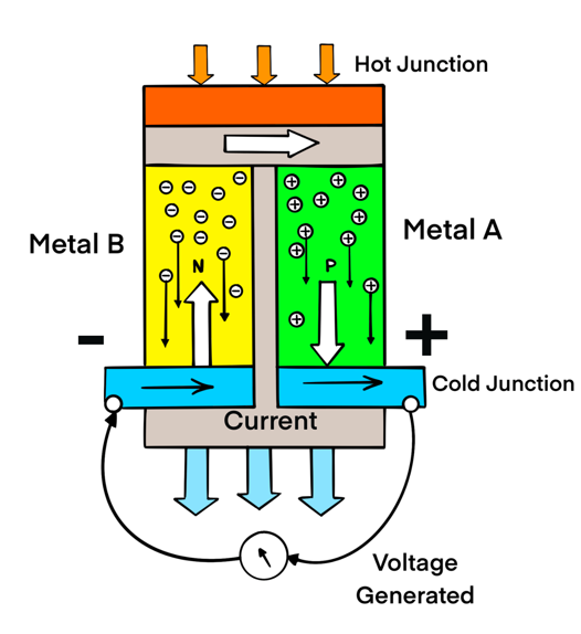
2.1 How the Seebeck Effect Works
When two dissimilar metals or alloys (let’s say metal A and metal B) are connected together to form a closed loop, and the two junctions are maintained at different temperatures:
-
A voltage is generated in the circuit.
-
This voltage is approximately proportional to the temperature difference between the two junctions.
-
The current flows due to the migration of charge carriers (electrons or holes) in response to the thermal gradient.
This EMF is known as the Seebeck voltage and is given by:
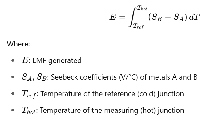
The Seebeck coefficient varies with material and temperature, making the choice of thermocouple materials critical for accuracy.
3. Thermocouple Construction
A thermocouple is made by joining two wires of dissimilar metals at one end to form the measuring junction (hot junction). The other ends of the wires are connected to a measuring device (like a voltmeter or temperature transmitter), which is kept at a known reference temperature (cold junction).
3.1 Components of a Thermocouple System
-
Hot Junction (Measuring Junction):
-
Located at the point where temperature needs to be measured.
-
The junction of two dissimilar metals is exposed to the process environment.
-
-
-
Cold Junction (Reference Junction):
-
Located at a known and stable reference temperature.
-
Typically compensated electronically using cold-junction compensation (CJC) circuits.
-
-
-
Thermocouple Wires:
-
Made of specified alloys (e.g., chromel, alumel).
-
Must be homogeneous and of high purity for consistent performance.
-
-
-
Protective Sheath (optional):
-
Protects the thermocouple from chemical, mechanical, or environmental damage.
-
4. Cold Junction Compensation (CJC)
The thermocouple measures temperature difference, not absolute temperature. The EMF generated depends on both the hot junction and the cold junction temperatures. To obtain the actual temperature at the hot junction, the temperature at the cold junction must be known or compensated.
4.1 Methods of Cold Junction Compensation
-
Ice Bath Reference: Traditional method using an ice-water bath at 0°C.
-
-
Electronic Compensation: Modern thermocouple transmitters or data acquisition systems include a built-in temperature sensor (like RTD or thermistor) to measure the ambient (cold junction) temperature and apply mathematical correction.
5. Types of Thermocouples
Thermocouples are classified based on the materials used. The most common types are standardized by ANSI (American National Standards Institute) and IEC. Some widely used types include:
| Type | Material Combination | Temperature Range (°C) | Sensitivity (mV/°C) | Applications |
|---|---|---|---|---|
| K | Chromel (Ni-Cr) / Alumel (Ni-Al) | -200 to 1250 | ~41 µV/°C | General purpose, oxidizing |
| J | Iron / Constantan | -40 to 750 | ~55 µV/°C | Reducing environments |
| T | Copper / Constantan | -200 to 350 | ~43 µV/°C | Low-temperature, cryogenics |
| E | Chromel / Constantan | -200 to 900 | ~68 µV/°C | High sensitivity applications |
| N | Nicrosil / Nisil | -200 to 1300 | ~39 µV/°C | High stability, newer type |
| R/S | Pt13Rh / Pt (R), Pt10Rh / Pt (S) | 0 to 1600 | ~10 µV/°C | High-temperature, inert env. |
| B | Pt30Rh / Pt6Rh | 0 to 1800 | ~6 µV/°C | Glass industry, furnaces |
6. Working Example
Let’s understand how a K-type thermocouple works:
-
Materials: Chromel (positive) and Alumel (negative)
-
Measuring junction: Exposed to a furnace at 800°C
-
Reference junction: At 25°C with CJC circuit
-
Output EMF: For the 775°C difference, the thermocouple generates approx. 33.25 mV
-
The EMF is measured by the connected device, and the actual hot junction temperature is displayed using calibration tables or linearization functions.
7. Characteristics of Thermocouples
7.1 Advantages
-
Wide temperature range: -200°C to +1800°C
-
Durable and robust: Can withstand harsh environments
-
Fast response: Especially in small-diameter probes
Simple construction
Self-powered: No external excitation required
7.2 Limitations
-
Non-linear output: Requires linearization
-
Cold junction compensation needed
-
Susceptible to electrical noise
-
Limited accuracy compared to RTDs
-
Deterioration over time: Especially at high temperatures
8. Factors Affecting Thermocouple Accuracy
Several factors influence the performance and accuracy of a thermocouple:
-
Homogeneity of materials
-
Reference junction stability
-
Thermoelectric EMF drift due to aging
-
Chemical contamination
-
Thermal cycling
-
Proper extension cable usage
It’s essential to use thermocouple-grade extension wires to avoid introducing unwanted EMFs.
9. Applications of Thermocouples
Thermocouples are used in a broad range of industries due to their versatility:
9.1 Industrial Applications
-
Power plants (boilers, turbines)
-
Oil and gas (furnaces, flare stacks)
-
Chemical and petrochemical plants
-
Steel and metal foundries
-
Cement kilns
-
Refineries
9.2 Scientific Applications
-
Laboratory testing
-
Aerospace and satellite temperature monitoring
9.3 Consumer and Commercial Use
-
Gas appliances
-
HVAC systems
-
Automotive sensors (e.g., exhaust gas temp)
-
Home ovens and heaters
10. Comparison with Other Temperature Sensors
| Feature | Thermocouple | RTD | Thermistor |
|---|---|---|---|
| Range | -200°C to 1800°C | -200°C to 650°C | -100°C to 150°C |
| Accuracy | Medium | High | Very high (limited) |
| Cost | Low to Medium | Medium to High | Low |
| Linearity | Poor | Good | Poor |
| Ruggedness | Excellent | Moderate | Poor |
| Response Time | Fast | Slow | Fast |
11. Conclusion
The thermocouple is a cornerstone of industrial and scientific temperature measurement, offering durability, simplicity, and broad applicability. Based on the Seebeck effect, its operation involves the generation of a thermoelectric voltage corresponding to a temperature difference between two junctions of dissimilar metals.
While not the most accurate device, thermocouples offer exceptional performance in environments where robustness, fast response, and wide temperature range are more critical than precision. Proper material selection, cold junction compensation, and adherence to best installation practices ensure reliable thermocouple performance across its lifetime.
Understanding the working principle and characteristics of thermocouples allows engineers and technicians to make informed choices in sensor selection, installation, and troubleshooting in various process control and instrumentation systems.