

1. Introduction to RTD
RTD stands for Resistance Temperature Detector. It is a temperature sensor that measures temperature by correlating the resistance of the RTD element with temperature. RTDs are widely used in industrial, laboratory, and commercial applications due to their accuracy, stability, repeatability, and linearity.
An RTD relies on the predictable change in the electrical resistance of metals with temperature. As the temperature increases, the resistance of the metal also increases in a known and repeatable way, making it suitable for precise temperature measurement.
2. Fundamental Principle of RTD
The RTD is based on the principle of electrical resistance of metals:
“The resistance of a pure metal increases with an increase in temperature.”
This characteristic is defined mathematically using the temperature coefficient of resistance (TCR).
Basic Relationship:

3. RTD Element Materials
RTDs are typically made using pure metals with stable and repeatable resistance-temperature characteristics. The most common materials used are:
Platinum (Pt)
Most widely used material
Chemically stable and corrosion-resistant
High accuracy and repeatability
Standard RTDs are often called Pt100 (100 ohms at 0°C)
Nickel (Ni)
Less expensive than platinum
More nonlinear response
Limited temperature range
Copper (Cu)
Excellent linearity
Limited temperature range
Susceptible to oxidation and corrosion
Among these, platinum RTDs are the industry standard, especially in industrial process control, due to their superior properties.
4. Temperature Coefficient of Resistance (α)
The temperature coefficient of resistance α\alpha is a material-specific constant that indicates how much the resistance of the material changes per degree Celsius.
For example, for platinum:
α≈0.00385 Ω/Ω/°C
This means a platinum wire of 100 Ω at 0°C will have approximately:
138.5 Ω at 100°C
119.25 Ω at 50°C
This predictable behavior allows accurate temperature measurement.
5. RTD Configuration Types
RTD Wire Configurations
To measure the resistance accurately and eliminate errors due to lead wire resistance, RTDs are typically wired in one of the following ways:
1. Two-wire RTD
Simplest configuration
One wire at each end of the RTD element
Lead wire resistance adds to the sensor resistance (error)
2. Three-wire RTD
Most common industrial configuration
Two wires on one end, one on the other
Assumes lead wire resistance is equal
Bridge circuit cancels out lead wire resistance
Offers a good balance of cost and accuracy
3. Four-wire RTD
Most accurate configuration
Completely eliminates the effect of lead wire resistance
Used in laboratory and precision measurements
6. RTD Working Circuit
To measure temperature using an RTD, the change in resistance must be detected accurately. There are two typical methods:
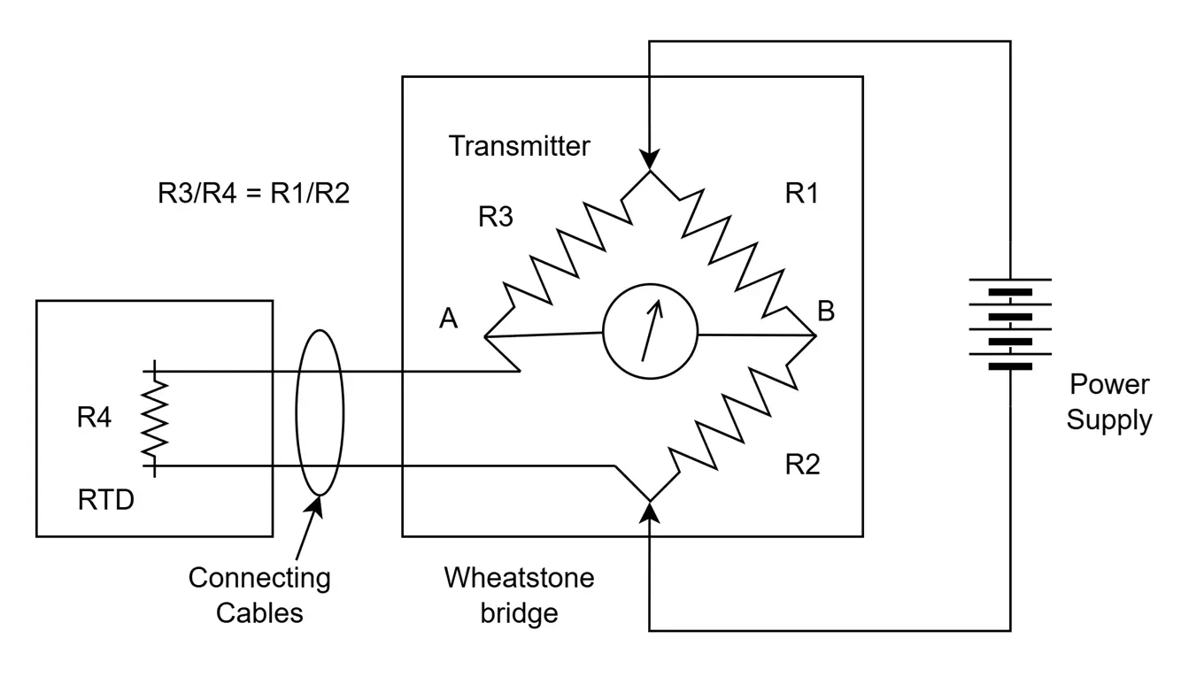
a. Wheatstone Bridge Circuit
A Wheatstone bridge is used to detect small changes in resistance.
The RTD forms one arm of the bridge.
As temperature changes, the resistance of the RTD changes.
This causes an imbalance in the bridge, generating a differential voltage.
This voltage is amplified and calibrated to display temperature.
b. Constant Current Source Method
A precise current (usually in the range of 1 mA) is passed through the RTD.
The voltage drop across the RTD is measured using Ohm’s law:
V=I⋅RV
As resistance changes with temperature, voltage changes accordingly.
This voltage is then used to calculate the temperature.
7. RTD Accuracy, Stability, and Linearity
Accuracy
RTDs are known for their high accuracy compared to thermocouples and thermistors. A typical Class A Pt100 RTD has an accuracy of ±0.15°C at 0°C.
Linearity
Platinum RTDs are nearly linear over a wide temperature range. However, for very precise applications, calibration tables or polynomial equations are used to account for slight non-linearity.
Stability
Platinum RTDs are extremely stable over time. They show very little drift even after years of operation, making them ideal for applications where long-term accuracy is critical.
8. RTD Standards
RTDs are manufactured in accordance with international standards such as:
IEC 60751 (International Standard)
Nominal resistance (e.g., 100 Ω at 0°C)
Tolerance classes (A, B, AA)
Temperature coefficient (usually 0.00385/°C for industrial RTDs)
Tolerance Classes:
Class AA: ±(0.1 + 0.0017 × |t|) °C
Class A: ±(0.15 + 0.002 × |t|) °C
Class B: ±(0.3 + 0.005 × |t|) °C
The higher the class, the better the accuracy.
9. RTD Response Time
The response time of an RTD depends on:
Element size and material
Sheath and insulation
Medium (air, liquid, or gas)
Installation (immersed, surface-mounted)
Generally, RTDs have a slower response time than thermocouples due to their construction and mass. However, for applications where speed is not critical, RTDs are preferred for their accuracy.
10. Applications of RTD
RTDs are used in many industrial, scientific, and commercial applications due to their reliability and accuracy.
Industrial Applications
Power plants
Refineries
Chemical industries
Food and beverage
Pharmaceutical processing
HVAC systems
Scientific Applications
Laboratories
Environmental monitoring
Meteorological instruments
Consumer Applications
Appliances
Air conditioners
Water heaters
11. Advantages of RTDs
High accuracy and precision
Excellent stability over time
Wide temperature range (typically −200°C to +600°C)
Repeatability: consistent readings over multiple cycles
Predictable and nearly linear output
Long-term reliability, especially in controlled environments
12. Limitations of RTDs
Higher cost compared to thermocouples and thermistors
Slower response time
Sensitivity to mechanical shock and vibration
Self-heating due to excitation current (must be minimized)
Requires careful lead wire compensation (especially for 2-wire)
13. RTD vs. Thermocouple vs. Thermistor
| Feature | RTD | Thermocouple | Thermistor |
|---|---|---|---|
| Sensing Element | Metal (e.g., platinum) | Dissimilar metals junction | Semiconductor |
| Accuracy | High | Moderate | High |
| Stability | Excellent | Fair | Poor over time |
| Linearity | Good | Poor | Poor |
| Temperature Range | −200 to +600°C | −200 to +1800°C | −100 to +150°C |
| Response Time | Slow | Fast | Very fast |
| Cost | Moderate to high | Low to moderate | Low |
14. RTD Calibration
RTDs can be calibrated against standard temperature references like ice baths (0°C), boiling water (100°C), or precision temperature baths. In industrial applications, smart transmitters with digital compensation are used to linearize and correct RTD outputs.
Calibration ensures:
Accuracy within specified tolerances
Detection of drift or damage
Compliance with quality systems (e.g., ISO 9001, FDA)
Conclusion
RTDs are highly accurate, stable, and reliable temperature sensors based on the principle that the resistance of a metal changes predictably with temperature. Platinum RTDs (especially Pt100) are the most widely used type due to their linear behavior and excellent long-term stability. Despite being more expensive than thermocouples or thermistors, RTDs offer superior performance in applications where precision and reliability are critical.
Their design, construction, and method of resistance measurement (2-wire, 3-wire, 4-wire) can be tailored to match the specific needs of industrial, laboratory, or commercial environments.