
The Liquefied Natural Gas Plant Process Explained
Liquefied Natural Gas (LNG) is a cornerstone of the modern global energy landscape. It’s the key that unlocks the ability to transport vast quantities of natural gas across oceans, connecting energy-rich regions with markets thousands of miles away. But how is this incredible feat accomplished? How do you take a gas from a reservoir deep within the earth and transform it into a transportable liquid?
The answer lies within the sophisticated and technologically advanced world of the LNG plant. These massive industrial complexes are marvels of modern engineering, designed to purify and chill natural gas to cryogenic temperatures, reducing its volume by over 600 times. This drastic reduction in volume is what makes long-distance shipping economically viable.
This comprehensive guide will walk you through the entire LNG plant process, from the moment the feed gas enters the facility to the point where the super-cooled LNG is loaded onto a specialized carrier. We’ll explore the critical stages of pre-treatment, the heart of the plant—liquefaction—and the final steps of storage and loading. Get ready for a journey into a world of extreme cold and high technology.
Stage 1: Gas Reception and Pre-Treatment
Before the liquefaction process can begin, the raw natural gas, known as feed gas, must be thoroughly cleaned. Natural gas straight from the reservoir contains various impurities that can freeze at the cryogenic temperatures required for liquefaction, causing blockages, damaging equipment, and compromising safety. The pre-treatment stage is designed to systematically remove these undesirable components.
Inlet Reception
The process begins at the inlet reception facilities. Here, the feed gas arrives from pipelines and its pressure, temperature, and flow rate are measured. The first step is often slug catching and separation, where any free liquids (like water and hydrocarbon condensates) and solid particles are removed from the gas stream.
Acid Gas Removal (AGR)
The most significant impurities are acid gases, primarily carbon dioxide () and hydrogen sulfide ().
Carbon Dioxide (): This is the main culprit for freezing. will solidify at LNG temperatures, forming a dry ice-like substance that can plug heat exchangers and other critical equipment. LNG specifications typically require levels to be below 50 parts per million (ppm).
Hydrogen Sulfide (): This compound is highly corrosive and toxic. Removing it is crucial for safety, environmental compliance, and protecting the integrity of the plant’s equipment. Gas with significant is called “sour gas,” while gas with very little is “sweet gas.”
The most common method for acid gas removal is amine treating. In this process, the feed gas is passed through a large absorption tower where it comes into contact with a flowing solution of amines (e.g., monoethanolamine – MEA, or methyldiethanolamine – MDEA). The amine solution selectively absorbs the and . The “rich” amine solution, now carrying the acid gases, is then heated in a separate regeneration column, which strips the acid gases out. The “lean,” regenerated amine is cooled and recycled back to the absorption tower, creating a continuous, closed-loop system. The stripped acid gases are then routed for further processing, often to a Sulfur Recovery Unit (SRU).
Dehydration – Getting Every Last Drop of Water
Even after the initial separation, the gas is still saturated with water vapor. Water () would freeze into ice, causing severe blockages. Therefore, the gas must be dehydrated to an extremely low level, typically less than 0.1 ppm.
This is accomplished using molecular sieve beds. These are large vessels filled with a solid adsorbent material, a type of zeolite, with microscopic pores of a precise and uniform size. These pores are small enough to trap water molecules while allowing the larger methane molecules to pass through unaffected. Typically, two or more beds are used in parallel. While one bed is actively dehydrating the main gas stream, the other is being regenerated. Regeneration involves passing a hot, dry stream of gas (often a slipstream of the product gas) through the saturated bed to drive off the captured water. This cycle ensures a continuous and uninterrupted dehydration process.
Mercury and Heavy Hydrocarbon Removal
Mercury (Hg): Although present in trace amounts (parts per billion), mercury is extremely detrimental. It can cause catastrophic corrosion, specifically liquid metal embrittlement, in the aluminum heat exchangers used in the cryogenic section. Mercury is removed by passing the gas through a non-regenerable adsorbent bed, typically sulfur-impregnated carbon, which captures the mercury.
Heavy Hydrocarbons (HHCs): Components like benzene, toluene, ethane, propane, and butane (collectively known as C5+ or Natural Gas Liquids – NGLs) have higher freezing points than methane. They can freeze and foul the cryogenic heat exchangers. These are removed in a scrub column or fractionation unit. This process cools the gas stream enough to condense out the heavier hydrocarbons, which are then separated. These NGLs are valuable byproducts and are often processed and sold separately.
After passing through all these pre-treatment steps, the natural gas is clean, dry, and ready for the main event: liquefaction.
Stage 2: Liquefaction
Liquefaction is the most technologically complex and energy-intensive part of the entire LNG process. This is where the magic happens, chilling the clean natural gas from ambient temperature down to approximately -162°C (-260°F). At this temperature, it transitions from a gas to a liquid, becoming LNG.
The core of the liquefaction process is a massive refrigeration cycle, similar in principle to a home refrigerator but on an unimaginably larger scale and operating at far lower temperatures. The unit that contains the key liquefaction equipment (compressors, heat exchangers, etc.) is called an LNG train. Modern LNG plants often have multiple trains operating in parallel to achieve their enormous production capacities.
There are several competing liquefaction technologies, but most fall into one of three main categories.
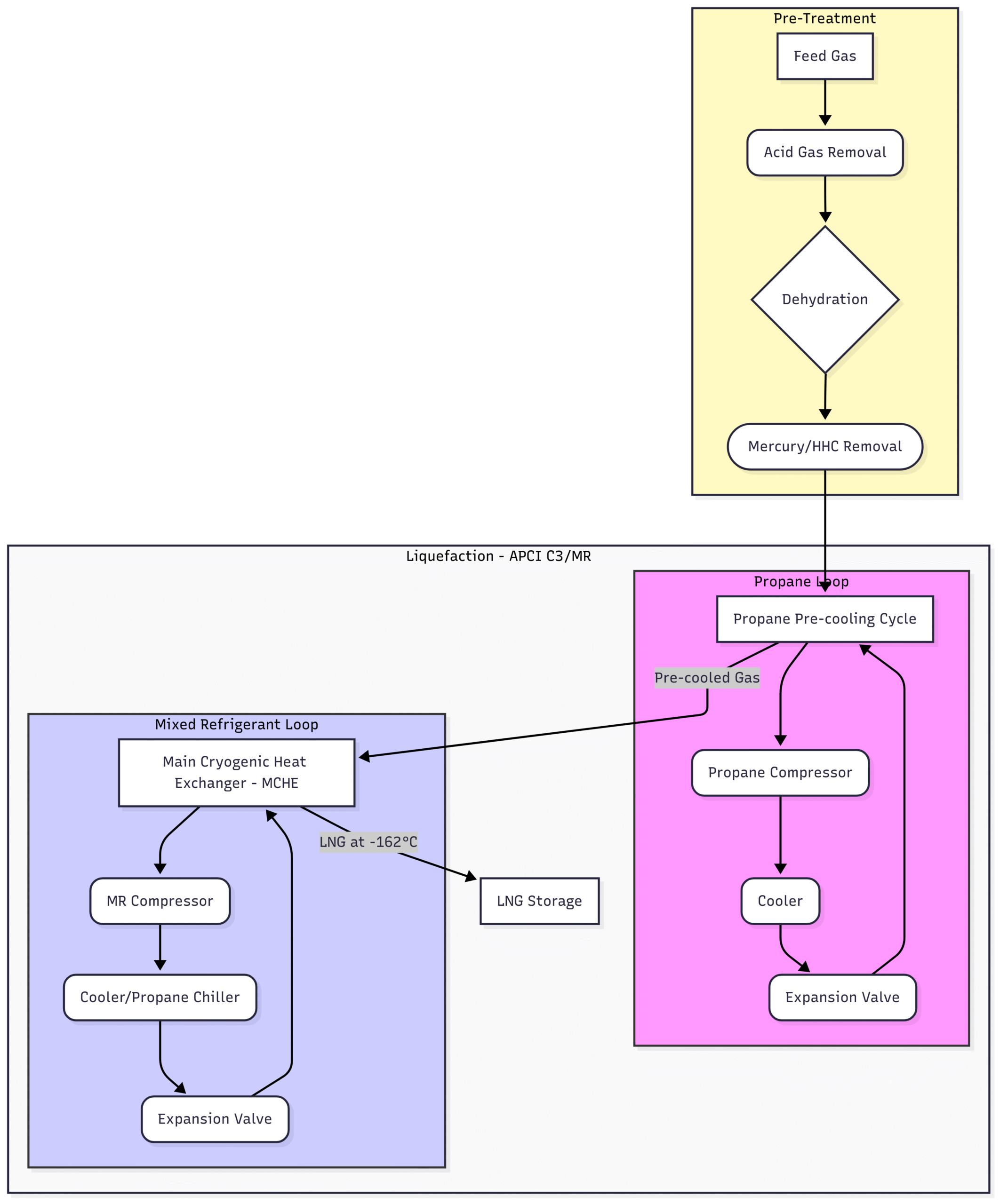
APCI C3/MR™ Process (Propane Pre-cooled Mixed Refrigerant)
The APCI C3/MR™ process is the most widely used technology in the LNG industry, accounting for a significant portion of global production. It uses two main refrigeration cycles in series:
Propane Pre-cooling Cycle: The treated natural gas first enters a series of heat exchangers where it is pre-cooled to about -35°C (-31°F) using pure propane as the refrigerant. The propane is compressed, cooled, and expanded in a closed loop to provide the initial stage of cooling.
Mixed Refrigerant (MR) Cycle: The pre-cooled gas then enters the Main Cryogenic Heat Exchanger (MCHE). This is a massive, often spiral-wound, heat exchanger. Here, the gas is further cooled and liquefied by a mixed refrigerant, which is a carefully blended cocktail of nitrogen, methane, ethane, and propane. This mixture is compressed and then cooled by the propane cycle before being expanded. The key advantage of a mixed refrigerant is that it evaporates over a wide range of temperatures, allowing for a very efficient cooling curve that closely matches the cooling curve of the natural gas. This thermodynamic efficiency is what makes the process so popular.
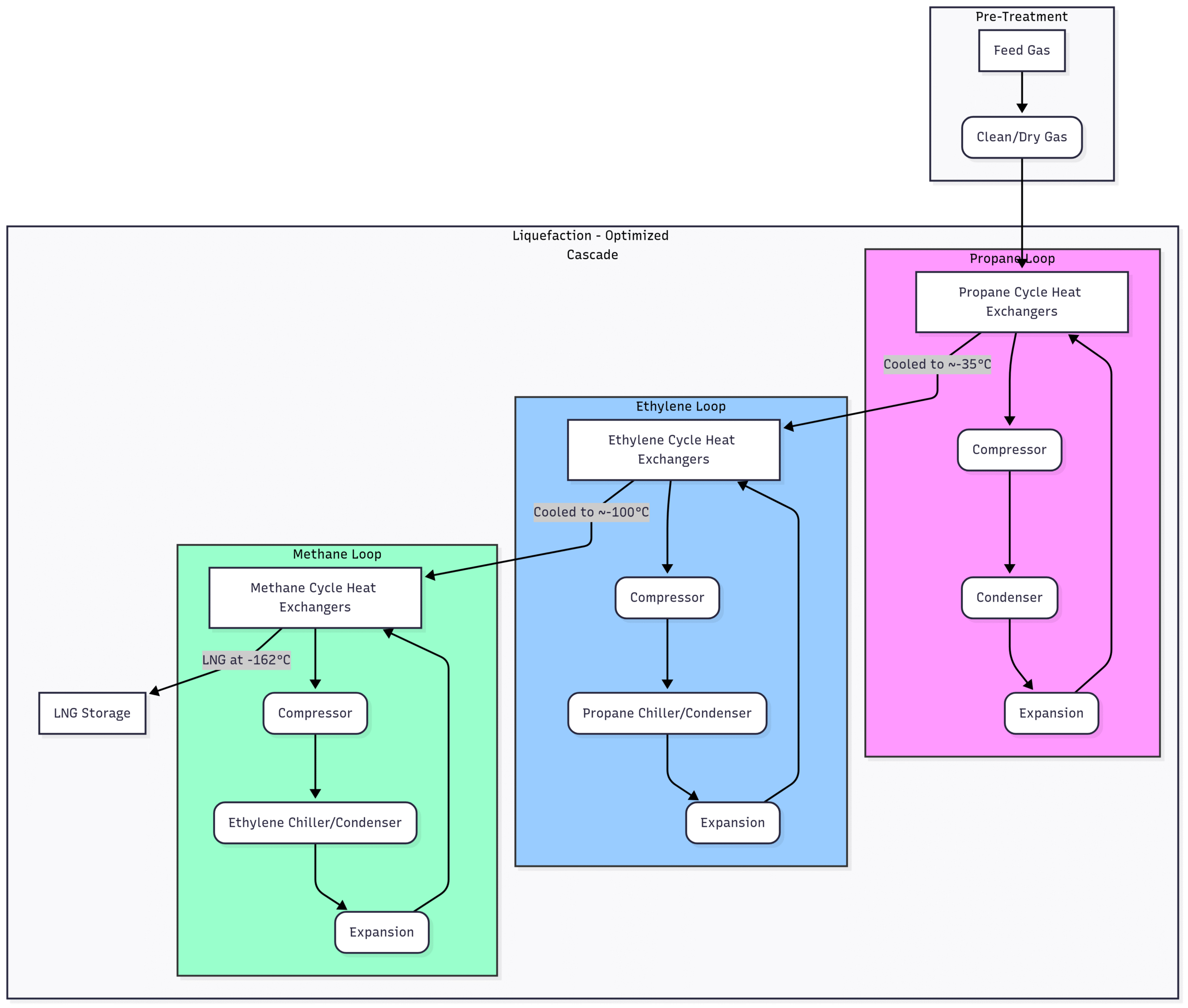
ConocoPhillips Optimized Cascade® Process
The Cascade process is another leading technology, known for its operational simplicity and robustness. Instead of using a mixed refrigerant, it uses a series of three progressively colder, pure refrigerant cycles in a “cascade.”
Propane Cycle: Similar to the APCI process, a closed-loop propane cycle provides the initial cooling, chilling the natural gas down to around -35°C.
Ethylene Cycle: The gas then moves to a second set of heat exchangers where it is cooled further by an ethylene (or ethane) refrigeration loop, taking the temperature down to approximately -100°C.
Methane Cycle: Finally, a methane refrigeration loop provides the final deep chilling, cooling the gas to its liquefaction point of -162°C.
Each refrigerant is compressed and condensed in its own closed loop. The propane cycle is used to condense the ethylene refrigerant, and the ethylene cycle is used to condense the methane refrigerant. While potentially less thermodynamically efficient on paper than the best MR processes, its use of pure refrigerants makes it easier to operate and start up.
Linde Mixed Fluid Cascade (MFC®) Process
The Linde MFC® process, also known as the Statoil/Linde process, combines features of both the cascade and mixed refrigerant technologies. It uses three mixed refrigerant loops instead of pure component loops.
Pre-cooling Cycle: Uses a mixed refrigerant of propane and butane to cool the natural gas.
Sub-cooling Cycle: Uses a mixed refrigerant of nitrogen and methane to provide the next stage of cooling.
Liquefaction Cycle: Uses a final mixed refrigerant of nitrogen, methane, and ethane for the deep chilling and liquefaction.
This approach aims to capture the high efficiency of mixed refrigerant cooling at each temperature stage, providing excellent overall plant efficiency. It often utilizes proprietary plate-fin heat exchangers developed by Linde.
Stage 3: LNG Storage – Keeping it Cool and Contained
Once liquefied, the LNG must be stored safely at its cryogenic temperature until a ship arrives for loading. This requires some of the most impressive structures in the energy industry: full-containment LNG storage tanks.
These tanks are essentially giant thermos bottles. They typically consist of:
Inner Tank: An inner tank made of a cryogenic material, usually 9% nickel steel, which can withstand the extreme cold without becoming brittle. This tank is in direct contact with the LNG.
Insulation: A thick layer of insulation, such as expanded perlite, is packed between the inner and outer tanks to minimize heat leak from the surroundings.
Outer Tank: A robust outer tank made of pre-stressed concrete, designed to withstand external impacts and contain the entire liquid volume in the unlikely event of an inner tank leak.
Vapor Barrier: A carbon steel liner is often attached to the inner wall of the concrete tank to ensure vapor tightness.
Boil-Off Gas (BOG) Management
Despite the heavy insulation, some heat will inevitably leak into the tank, causing a small amount of LNG to vaporize back into a gas. This is called Boil-Off Gas (BOG). Managing BOG is a critical aspect of LNG storage and shipping. BOG increases the pressure inside the tank, which must be controlled. In a modern LNG plant, this BOG is not wasted or flared. It is collected, re-compressed, and typically used as fuel gas for the gas turbines that drive the refrigerant compressors, improving the overall efficiency of the plant.
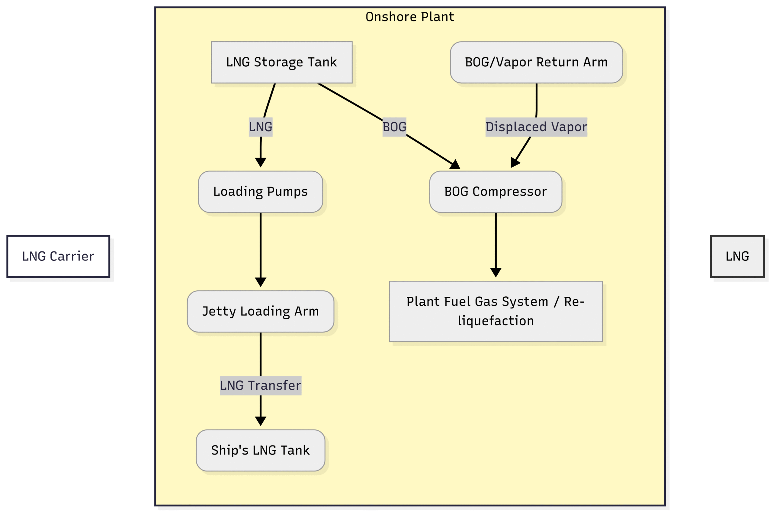
Stage 4: LNG Loading
The final step in the LNG plant process is loading the product onto specialized LNG carriers. These ships are also equipped with insulated, cryogenic tanks similar in principle to the onshore storage tanks.
The loading process is conducted at a dedicated jetty.
Loading Arms: LNG is transferred from the storage tanks to the ship via articulated, insulated loading arms. These are complex pieces of machinery with multiple swivels to allow them to move with the ship as it shifts with tides and loading.
Vapor Return: As the ship’s tanks are filled with cold LNG, the warmer vapor already inside them is displaced. This vapor is sent back to the shore via a separate vapor return arm. This returned vapor is managed along with the storage tank BOG, typically being used as fuel or re-liquefied.
Safety Systems: The entire loading process is monitored by sophisticated control systems. Emergency Shutdown (ESD) systems can automatically stop the flow and disconnect the arms in seconds if any problem is detected, such as a leak or excessive ship movement.
Once loading is complete, the carrier is ready to set sail, transporting the energy across the globe to regasification terminals where the LNG will be converted back into a gas and sent to consumers.
Conclusion:
The liquefied natural gas plant process is a remarkable symphony of chemical, mechanical, and cryogenic engineering. From the meticulous purification of the feed gas to the intense cold of the liquefaction cycle and the robust design of the storage and loading systems, every step is optimized for efficiency, reliability, and above all, safety.
As the world continues to seek cleaner and more flexible energy sources, the role of LNG is set to expand. Understanding the intricate process that transforms natural gas into a globally traded commodity reveals the incredible ingenuity required to power our modern world. The journey from gas field to LNG carrier is a cold, complex, and critically important one, ensuring that clean-burning natural gas can reach every corner of the planet.
Fabulous – many thanks!
Detailed, yet easy enough to understand. Thanks for the Knowledge!