
Understanding DCS Power Supply Requirements (UPS & Non-UPS)
A Distributed Control System (DCS) acts as the central nervous system for many critical industrial processes, from oil and gas refineries to power generation plants and chemical processing facilities. These sophisticated systems rely on a network of controllers, sensors, actuators, and human-machine interfaces (HMIs) working in concert to monitor and manage complex operations in real time. Ensuring the continuous and reliable operation of a DCS is paramount, as any disruption can lead to significant financial losses, safety hazards, and environmental consequences.
One of the most fundamental yet often overlooked aspects of a robust DCS infrastructure is its power supply system. Just like the human brain needs a constant flow of energy to function, a DCS requires a stable and dependable power source to perform its vital tasks. Understanding the power supply requirements for a DCS, particularly the roles of Uninterruptible Power Supplies (UPS) and Non-UPS power, is crucial for system designers, engineers, and maintenance personnel.
This comprehensive blog post will delve into the intricacies of DCS power supply requirements, exploring the necessity of both UPS and Non-UPS power, their specific applications within the system, redundancy considerations, and best practices for ensuring a reliable and resilient DCS operation. We will also utilize Mermaid block diagrams to provide clear visual representations of typical DCS power architectures.
The Critical Role of Reliable Power in DCS Operation
Imagine a scenario where the power to a refinery’s control system suddenly goes down. Valves could freeze in their current positions, critical monitoring systems would cease to function, and the entire process could grind to a halt, potentially leading to dangerous situations. This highlights why a well-designed power supply system is not just a convenience but an absolute necessity for a DCS.
A reliable power supply ensures:
Continuous Operation: Prevents process disruptions and downtime, maximizing productivity and minimizing financial losses.
Data Integrity: Safeguards critical process data from corruption or loss during power fluctuations or outages.
Operator Safety: Ensures that safety-critical functions, alarms, and emergency shutdown systems remain operational in all circumstances.
Equipment Protection: Protects sensitive electronic components within the DCS from damage caused by power surges, sags, or noise.
Controlled Shutdowns: Enables safe and orderly shutdown procedures in the event of a prolonged power failure, minimizing risks to personnel and equipment.
To achieve this level of reliability, DCS power systems typically employ a combination of power sources, including the main AC power supply, UPS systems, and sometimes DC power sources. Understanding when and where to utilize each of these is key to designing an effective power infrastructure.
Understanding Non-UPS Power in a DCS
Non-UPS power refers to the direct supply of AC power from the main electrical grid or a dedicated power distribution system within the industrial facility. This is the primary source of power for many components within a DCS that are either less critical for immediate safety and control during brief power interruptions or have their own internal power conditioning.
Components often powered by Non-UPS sources in a DCS include:
Engineering Workstations: These are typically used for system configuration, software development, and historical data analysis. While important, temporary loss of power to these workstations generally doesn’t directly impact the real-time control of the process.
Historian Servers: These servers store large amounts of process data. While data loss during a power outage is undesirable, a UPS might not be economically justifiable for extended backup, especially if the critical control functions are protected.
Network Infrastructure (Non-Critical): Some less critical network switches or communication devices might be powered by Non-UPS sources. However, core network components essential for controller communication are usually backed up by UPS.
Building and Infrastructure Systems: Lighting, HVAC, and other building-related systems within the control room are typically powered by Non-UPS sources.
Advantages of using Non-UPS power:
Cost-Effective: Direct connection to the main power supply is generally less expensive than implementing and maintaining UPS systems.
Simplicity: The power distribution is straightforward, without the added complexity of battery backups and power inverters.
Limitations of Non-UPS power:
Susceptibility to Power Disturbances: Directly connected equipment is vulnerable to power outages, sags, surges, and noise from the electrical grid.
No Backup Power: In the event of a power failure, equipment powered by Non-UPS will immediately lose power.
Mermaid Block Diagram: Non-UPS Power Distribution
To visualize a basic Non-UPS power distribution within a DCS, consider the following block diagram:
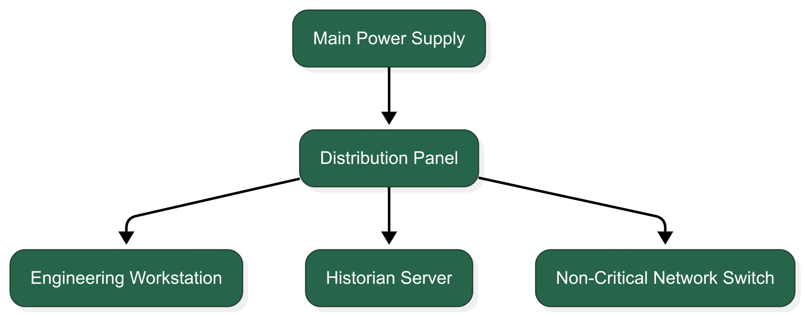
Explanation of the Diagram:
A (Main Power Supply): Represents the primary source of AC power.
B (Distribution Panel): Distributes the power to various loads.
C (Engineering Workstation): An example of a component often powered by Non-UPS.
D (Historian Server): Another component that might be on Non-UPS power.
E (Non-Critical Network Switch): A less critical network device powered directly.
This diagram illustrates a simple scenario where certain DCS components receive power directly from the main supply without any backup.
The Indispensable Role of UPS Power in a DCS
An Uninterruptible Power Supply (UPS) is a critical component in a DCS power system designed to provide a continuous and stable supply of electrical power to essential equipment during power outages, voltage fluctuations, and other power disturbances. A UPS typically consists of batteries, a rectifier (to convert AC to DC for charging the batteries), and an inverter (to convert DC back to AC to power the connected equipment).
Key functions of a UPS in a DCS:
Backup Power: Provides immediate power from its batteries when the main AC power fails, ensuring uninterrupted operation of critical components for a определенное время (predetermined time).
Power Conditioning: Filters out noise, stabilizes voltage levels, and protects sensitive electronic equipment from surges and sags, improving their lifespan and reliability.
Ride-Through Capability: Can often bridge brief power interruptions or sags without switching to battery power, preventing minor disturbances from affecting the DCS.
Controlled Shutdown: In the event of a prolonged power outage, the UPS allows for a controlled and orderly shutdown of the DCS, preventing data loss and equipment damage.
Critical DCS components that MUST be powered by UPS:
Process Controllers: These are the “brains” of the DCS, executing control algorithms and communicating with field devices. Any interruption to their power supply can lead to loss of control and potentially unsafe conditions.
Input/Output (I/O) Modules: These modules interface with sensors and actuators in the field. Loss of power to I/O modules would sever the DCS’s connection to the process.
Critical Network Infrastructure: Core network switches and communication buses that facilitate real-time data exchange between controllers, I/O modules, and HMIs are vital and must be UPS-protected.
Human-Machine Interfaces (HMIs): Operator consoles and displays provide the primary interface for monitoring and controlling the process. Their continuous operation is essential for situational awareness and timely intervention.
Safety Instrumented Systems (SIS): These independent systems are designed to automatically take the process to a safe state in case of critical failures. Their power supply must be highly reliable and is almost always backed up by a dedicated UPS.
Emergency Shutdown (ESD) Systems: Similar to SIS, ESD systems require uninterrupted power to perform their critical safety functions.
Mermaid Block Diagram: UPS Integration in DCS Power Distribution
Here’s a Mermaid block diagram illustrating how a UPS is typically integrated into a DCS power system to protect critical components:
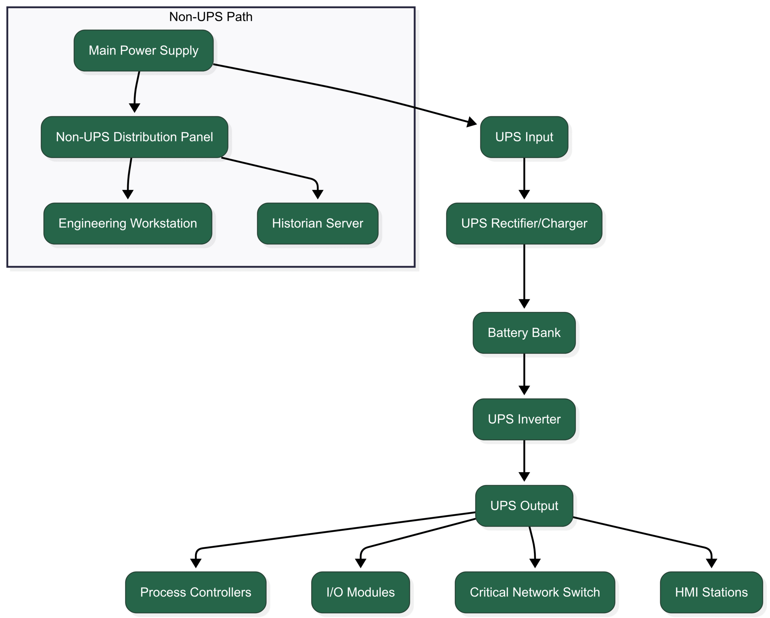
Explanation of the Diagram:
A (Main Power Supply): The primary AC power source.
B (UPS Input): The AC input to the UPS system.
C (UPS Rectifier/Charger): Converts AC to DC to charge the battery bank.
D (Battery Bank): Stores energy to provide backup power.
E (UPS Inverter): Converts DC from the batteries back to AC for the protected load.
F (UPS Output): The conditioned and backed-up AC power from the UPS.
G (Process Controllers), H (I/O Modules), I (Critical Network Switch), J (HMI Stations): Examples of critical DCS components powered by the UPS.
Subgraph (Non-UPS Path): Illustrates components powered directly from the main supply through a separate distribution panel.
K (Non-UPS Distribution Panel): Distributes Non-UPS power.
L (Engineering Workstation), M (Historian Server): Examples of Non-UPS powered components.
This diagram clearly shows how the UPS acts as an intermediary between the main power supply and the most critical elements of the DCS, ensuring a clean and uninterrupted power flow.
Redundancy in DCS Power Supply Systems
For highly critical applications where even brief power interruptions can have severe consequences, redundancy in the power supply system is often implemented. This involves having backup power sources and distribution paths to ensure that a single point of failure does not lead to a complete loss of power to critical components.
Common redundancy strategies in DCS power systems include:
Redundant UPS Systems: Employing two or more UPS units in parallel or in a master/slave configuration. If one UPS fails, the other(s) can take over the load without interruption.
Dual Power Supplies in Critical Modules: Many critical DCS components, such as controllers and I/O modules, are designed with redundant internal power supplies. These can be powered from separate UPS feeds or even a combination of UPS and a highly reliable Non-UPS source.
Redundant Power Distribution Paths: Utilizing multiple power distribution panels and wiring pathways to critical equipment, fed from different power sources or UPS units.
Automatic Transfer Switches (ATS): These devices automatically switch the power source to a backup supply (e.g., from the main UPS to a secondary UPS or a generator) in the event of a failure in the primary source.
Mermaid Block Diagram: Redundant UPS Configuration
The following Mermaid diagram illustrates a simplified redundant UPS configuration for critical DCS components:
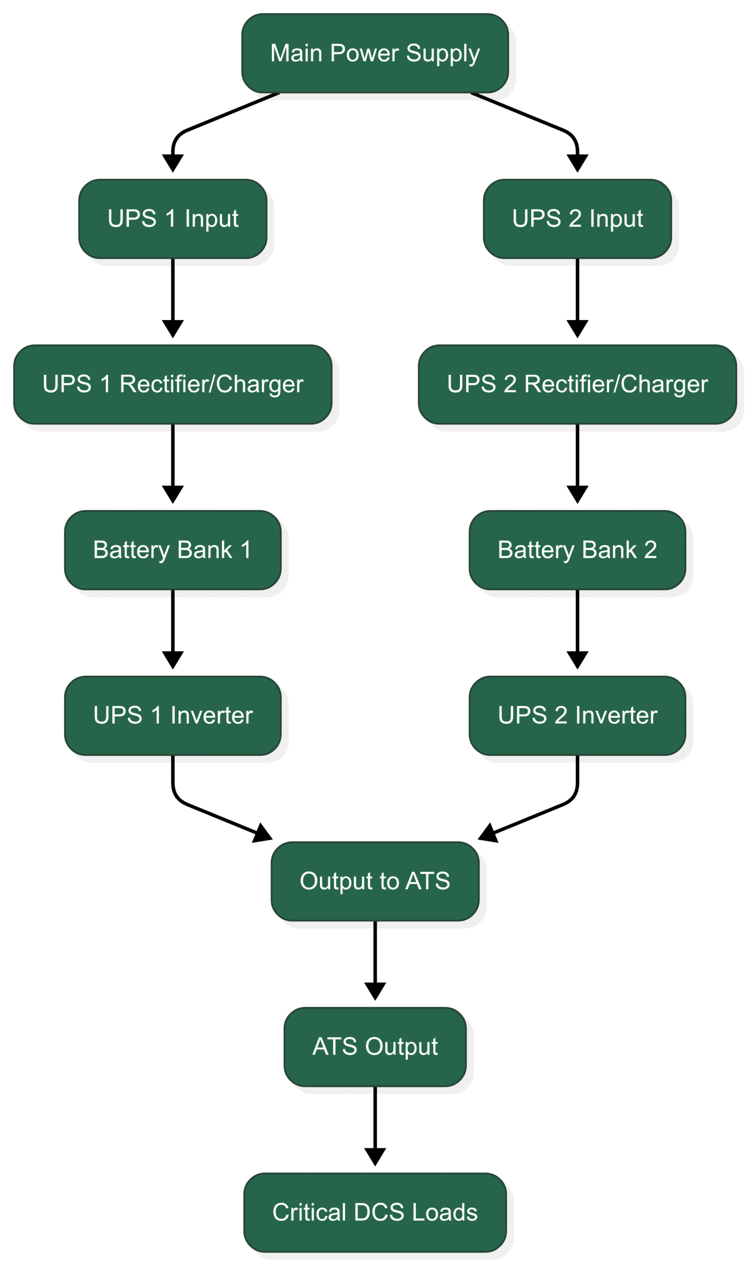
Explanation of the Diagram:
A (Main Power Supply): The primary power source.
B (UPS 1 Input), C (UPS 2 Input): Inputs to two redundant UPS systems.
D (UPS 1 Rectifier/Charger), E (UPS 2 Rectifier/Charger): Charging circuits for the respective UPS batteries.
F (Battery Bank 1), G (Battery Bank 2): Battery backups for each UPS.
H (UPS 1 Inverter), I (UPS 2 Inverter): Inverters converting DC to AC.
J (Output to ATS): Outputs from both UPS units connected to an Automatic Transfer Switch.
K (ATS Output): The output of the ATS, which selects the active power source.
L (Critical DCS Loads): The protected critical DCS components.
This setup ensures that if one UPS fails, the ATS will automatically switch to the other UPS, providing seamless power to the critical loads.
Best Practices for DCS Power Supply Systems
Designing and maintaining a reliable DCS power supply system requires careful consideration and adherence to best practices:
Thorough Load Analysis: Accurately determine the power requirements of all DCS components, including their peak and continuous power consumption.
Proper UPS Sizing: Select UPS systems with adequate capacity to support the connected load for the required backup time, considering future expansion.
Regular Battery Maintenance: Implement a strict maintenance schedule for UPS batteries, including regular inspections, testing, and timely replacement, as batteries are the most common point of failure in a UPS system.
Environmental Considerations: Ensure that UPS systems and batteries are installed in a clean, temperature-controlled environment to maximize their lifespan and performance.
Redundancy Where Necessary: Implement redundancy in power sources, UPS systems, and distribution paths for critical applications where downtime is unacceptable.
Proper Grounding and Wiring: Follow industry standards and best practices for grounding and wiring to minimize electrical noise and ensure safety.
Surge Protection: Install appropriate surge protection devices at the main power input and for sensitive electronic equipment to protect against voltage spikes.
Remote Monitoring and Alarms: Implement systems to monitor the status of UPS units and provide alerts in case of power failures, low battery levels, or other issues.
Regular Testing: Periodically test the UPS systems under load to verify their functionality and backup capabilities.
Documentation: Maintain detailed documentation of the DCS power system architecture, including wiring diagrams, equipment specifications, and maintenance procedures.
Compliance with Standards: Adhere to relevant industry standards and regulations related to electrical safety and power quality.
Conclusion: The Foundation of a Reliable DCS
The power supply system is the often-unseen but absolutely critical foundation upon which the reliable operation of a Distributed Control System rests. Understanding the distinct roles of UPS and Non-UPS power, implementing appropriate redundancy measures, and adhering to best practices in design, installation, and maintenance are essential for ensuring the continuous, safe, and efficient operation of industrial processes. By carefully considering the power requirements of each DCS component and implementing a robust power infrastructure, including strategically placed UPS systems for critical elements, organizations can significantly mitigate the risks associated with power disruptions and safeguard their valuable operations