
The Types and Importance of Grounding and Shielding in PLC Installations
In the heart of modern manufacturing, automation, and industrial processing lies a powerful and unassuming brain: the Programmable Logic Controller (PLC). These ruggedized computers are the workhorses that orchestrate complex machinery with incredible precision. But for a PLC to function reliably, its sensitive digital brain must be protected from the chaotic electrical environment of the factory floor. This is where two of the most critical, yet often misunderstood, concepts in industrial automation come into play: grounding and shielding.
Neglecting proper grounding and shielding is like building a skyscraper on a foundation of sand. It might stand for a while, but it’s destined for failure. Intermittent faults, phantom signal readings, and sudden system crashes can often be traced back to electrical noise that proper installation practices could have prevented. This comprehensive guide will delve into the types and profound importance of grounding and shielding in PLC installations, exploring everything from fundamental safety grounding to advanced signal protection techniques.
Understanding Electrical Noise:
Before we can appreciate the solution, we must first understand the problem. Industrial environments are electrically “loud.” The air is saturated with invisible energy fields that can wreak havoc on the low-voltage DC signals that PLCs rely on. This “electrical noise” is a broad term for unwanted electrical signals that superimpose themselves onto the desired signals. The primary culprits are:
-
Electromagnetic Interference (EMI): This is noise generated by the magnetic fields associated with large electrical currents. Think of motor starters, high-power cables, variable frequency drives (VFDs), solenoids, and welding equipment. When a motor kicks on, it creates a powerful magnetic field that can induce a voltage in any nearby wires, including sensitive PLC signal cables.
-
-
Radio Frequency Interference (RFI): This is a subset of EMI that occurs at higher frequencies. Sources include radio transmitters (like walkie-talkies), cellular devices, and the switching electronics found in VFDs and power supplies. RFI can couple into circuits and corrupt data, leading to communication errors and erratic PLC behavior.
-
-
Electrostatic Discharge (ESD): A sudden discharge of static electricity can create a high-voltage spike that can permanently damage the sensitive input/output (I/O) components of a PLC.
-
-
Power Line Disturbances: Fluctuations, surges, and sags in the main AC power supply can also couple into the PLC’s control circuits if not properly isolated.
When this noise infiltrates a PLC system, it can cause a range of problems, from minor glitches to catastrophic failures:
-
-
False Readings: A noise spike on an analog input cable can make the PLC think a tank level is higher than it is, causing an overflow.
-
-
Incorrect Commands: Noise on an output signal could cause a motor to start or stop at the wrong time.
-
-
Data Corruption: Communication between the PLC and other devices (like an HMI or another PLC) can become garbled.
-
-
System Halts: Severe noise can overwhelm the PLC’s processor, causing it to fault and shut down the entire process.
Grounding and shielding are the two primary weapons in our arsenal to combat this invisible enemy and ensure the integrity of our control systems.
The Foundation of Stability: Grounding (Earthing) 
Grounding, or earthing as it’s known in many parts of the world, is the practice of creating an intentional, low-impedance conductive path between electrical equipment and the earth itself. The Earth is considered to be at zero electrical potential and acts as a massive, stable reference point. Grounding serves two distinct but equally vital purposes: safety and signal integrity.
Safety Grounding (Body Earthing)
This is the most critical function of grounding and is mandated by electrical codes worldwide. Body earthing involves connecting all non-current-carrying metallic parts of an enclosure—like the PLC chassis, cabinet doors, and mounting panels—to the facility’s safety ground system.
Purpose: The primary goal is to protect people from electric shock. In the event of an internal fault where a “hot” wire accidentally touches the metal chassis, a proper safety ground provides a safe path for the fault current to flow to the earth. This massive flow of current will trip a circuit breaker or blow a fuse, immediately de-energizing the circuit and preventing the enclosure from becoming dangerously electrified. Without it, anyone touching the cabinet could become the path to the ground, resulting in severe injury or death.
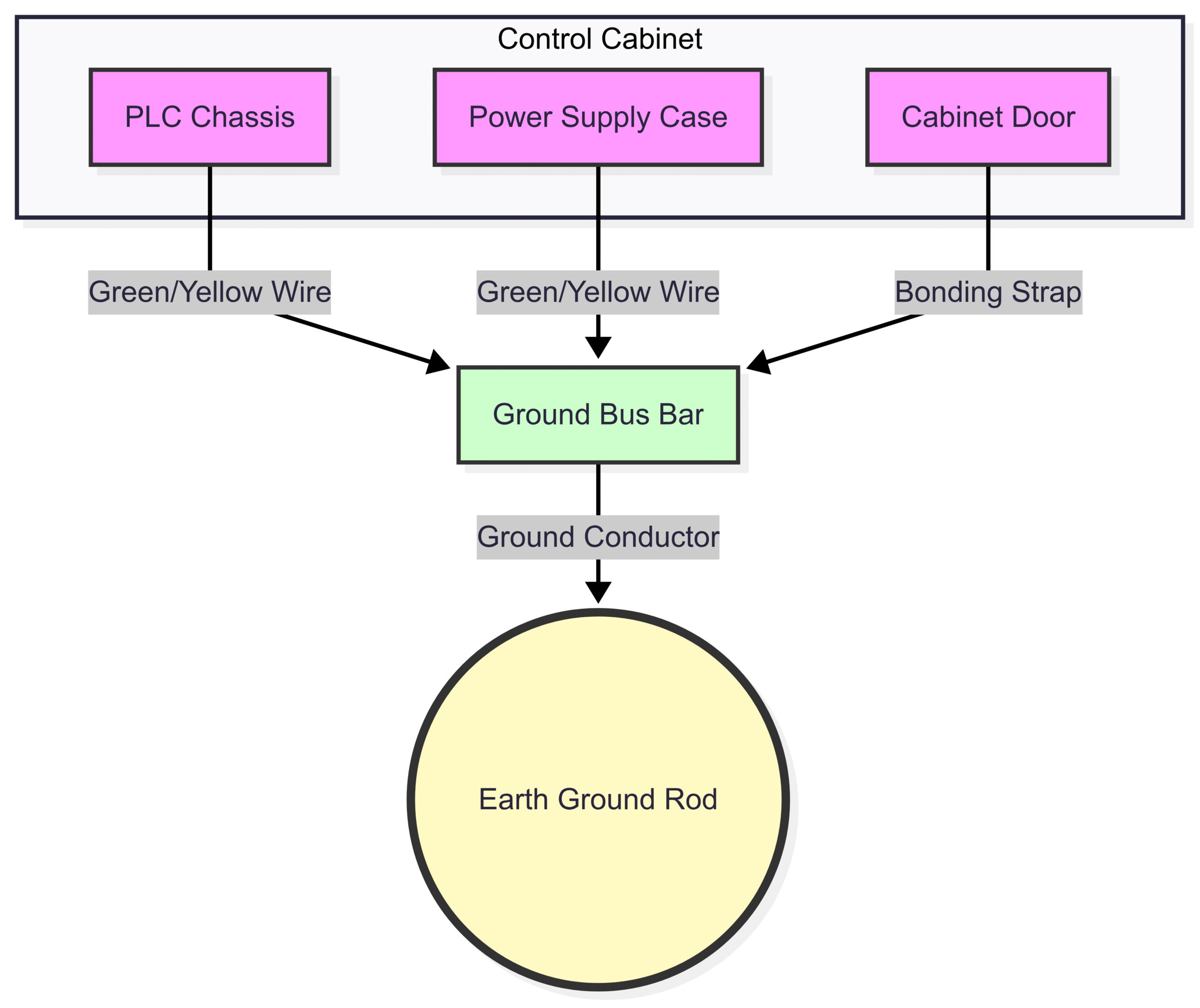
Diagram: A simple representation of safety grounding (body earthing), where all metallic components are tied to a common ground bus, which is then connected to the earth.
Signal Grounding (Signal Earthing)
While safety grounding protects people, signal grounding protects the process. The low-voltage DC signals used by PLC I/O (e.g., 4-20mA, 0-10V, 24VDC) need a stable and clean reference point to be measured against. This is the role of the signal ground. It provides the zero-volt reference plane for all control circuits.
Purpose: The main goal of signal grounding is to minimize the effects of electrical noise on the control signals. By providing a low-impedance path to the ground, it helps to drain away noise currents before they can disrupt the signal. However, if not done correctly, the signal ground system itself can become a source of noise. This is why understanding different grounding schemes is crucial.
Types of Grounding Systems in PLC Installations
There is no single “one-size-fits-all” grounding strategy. The best approach depends on the application, the types of signals involved, and the electrical environment. The overarching goal is to prevent ground loops—unwanted currents flowing between two points that are supposed to be at the same ground potential.
Single-Point Grounding
This is the most widely recommended grounding scheme for typical PLC systems, which operate at relatively low frequencies (DC to a few MHz). In a single-point grounding system, all signal grounds, power supply commons, and chassis grounds within a single cabinet are brought to a single, common point, which is then connected to the main facility ground.
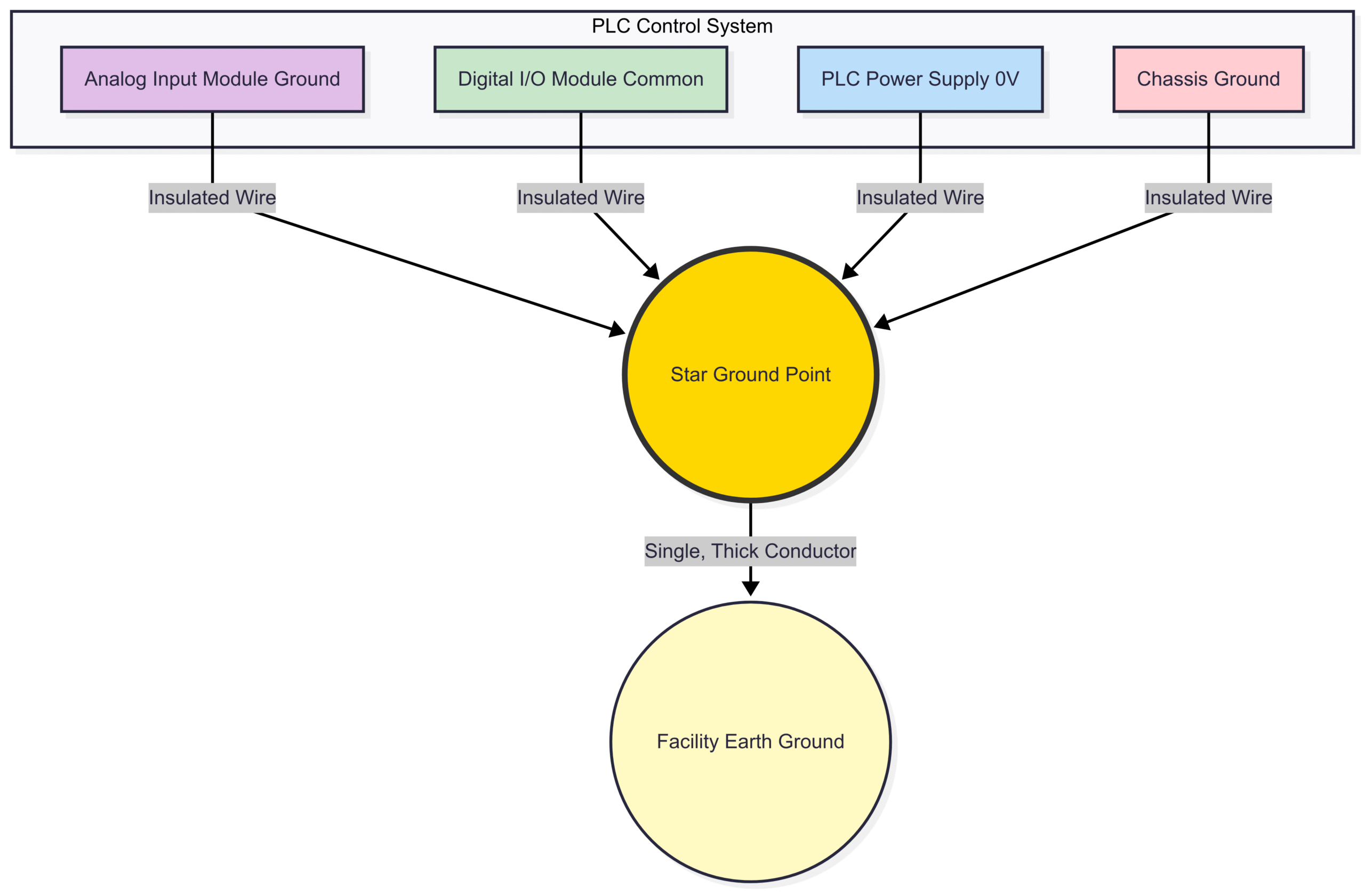
Diagram: A Single-Point Grounding scheme where all ground connections from different parts of the system are brought to one central point (the Star Ground Point) before being connected to the main earth ground. This prevents ground loop currents from flowing between the different subsystems.
The primary advantage of this method is that it eliminates potential differences between the ground references of different devices in the cabinet, thus preventing noise currents from flowing between them. A popular implementation of this is Star Grounding, where the connections radiate from the central point like the rays of a star.
Multi-Point Grounding
In multi-point grounding, system components are grounded directly to the nearest available chassis or ground plane. This method is generally used for very high-frequency (RF) systems where wire lengths become critical. At high frequencies, even a short ground wire can have significant impedance, making a single-point system ineffective.
For most PLC applications, multi-point grounding is not recommended for signal grounds as it is highly susceptible to creating low-frequency ground loops. These loops can act like antennas, picking up EMI from the environment.
Grounding Best Practices
-
Separate Your Grounds: While all grounds ultimately connect to the earth, keep them separate until the final star point. Have a dedicated bus bar for safety grounds (chassis), another for “noisy” DC commons (from solenoids, relays), and a third for “clean” analog signal grounds.
-
Use Thick, Short Wires: Ground conductors should have the lowest possible impedance. This is achieved by using thick-gauge wire (as thick as or thicker than the power conductors) and keeping the length as short as physically possible.
-
Use Braided Straps: For bonding cabinet doors and backplanes, use flat, braided straps. They have lower impedance at higher frequencies than round wires of the same cross-sectional area.
-
Clean Your Connections: Ensure all ground connections are to bare metal. Scrape away any paint, coatings, or oxidation to ensure a solid, low-resistance connection. Apply an anti-oxidant compound to prevent future corrosion.
-
Never Use the Safety Ground as a Signal Return: The safety ground conductor is for fault currents only. It is often electrically noisy and should never be used as the return path for any control or communication signal.
The First Line of Defense: Shielding 
If grounding is the foundation, shielding is the fortress wall. A shield is a metallic layer surrounding a signal conductor or a group of conductors within a cable. It acts like an interceptor, capturing electrical noise (EMI and RFI) and diverting it harmlessly to the ground before it can reach the signal wires inside.
For PLC systems, using shielded cable for all analog signals (e.g., 4-20mA, 0-10V, RTD, thermocouple) and high-speed communication lines (e.g., Ethernet/IP, Profibus) is non-negotiable for a reliable installation.
How Shielding Works
The shield works on the principle of the Faraday cage. An external electrical field will cause charges to rearrange on the surface of the conductive shield, creating an opposing field that cancels the external field’s effect on the interior conductors. For this to work effectively, the captured noise energy must have a path to drain away, which is provided by the ground connection.
Types of Shields
-
Foil Shield: Consists of a thin layer of aluminum foil, typically bonded to a polyester backing for strength. It provides 100% coverage and is excellent at blocking high-frequency RFI. It is usually paired with a bare drain wire for terminating the shield.
-
Braided Shield: A woven mesh of tinned copper wires. It provides excellent structural integrity and is more effective than foil at blocking lower-frequency EMI. Coverage is typically 70-95%.
-
Combination Shield: The best of both worlds, using both a foil and a braid shield. This provides maximum protection across a wide range of frequencies and is the preferred choice for cables running through extremely noisy environments.
The Golden Rule of Shielding: Ground at ONE End Only
This is perhaps the most critical and most frequently violated rule in PLC wiring. For low-frequency signals, which encompass the vast majority of PLC analog I/O, the cable shield should be connected to the ground at only one end. Typically, this connection is made at the PLC or source end. The other end of the shield (at the field device/sensor) should be cut back, insulated with heat shrink, and left floating (unconnected).
Why? Connecting the shield at both ends creates a ground loop. Because the ground potential at the PLC cabinet and the ground potential at the field sensor are rarely identical, a small voltage difference will exist. This voltage difference will drive a current through the low-resistance path of the shield. This current flowing through the shield creates its own magnetic field, which induces noise directly onto the signal wires it was meant to protect, completely defeating its purpose.
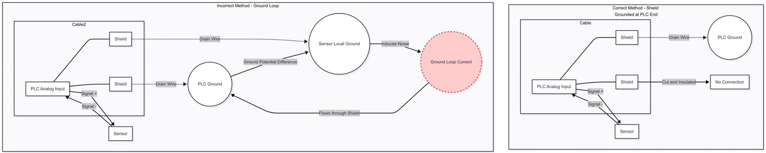
Diagram: Illustrating the correct and incorrect way to terminate a cable shield. Grounding at only one end (top) prevents noise-inducing ground loops, while grounding at both ends (bottom) creates a path for ground loop current to flow, contaminating the signal.
Exception: The “ground at one end” rule applies to low-frequency signals. For very high-frequency data communications (hundreds of MHz or GHz), grounding the shield at both ends is often recommended to provide a continuous, low-impedance path to the ground for RF energy. However, for standard PLC analog and digital I/O, always follow the one-end rule.
Integrating Grounding and Shielding: A Holistic Approach
Grounding and shielding are not separate tasks; they are two parts of a single, integrated system for noise immunity.
-
Shielding is the first line of defense that stops noise from reaching the signal wires.
-
Grounding is the system that safely drains that captured noise away.
A shield that isn’t properly grounded is just a floating antenna. A grounding system without shielded cables leaves the signals exposed. A successful installation requires careful planning of both. Signal wires must be routed away from high-power AC lines. Where they must cross, they should do so at a 90-degree angle to minimize magnetic coupling. The entire system—from the cabinet’s single-point ground to the termination of each individual shield drain wire—must be executed with precision.
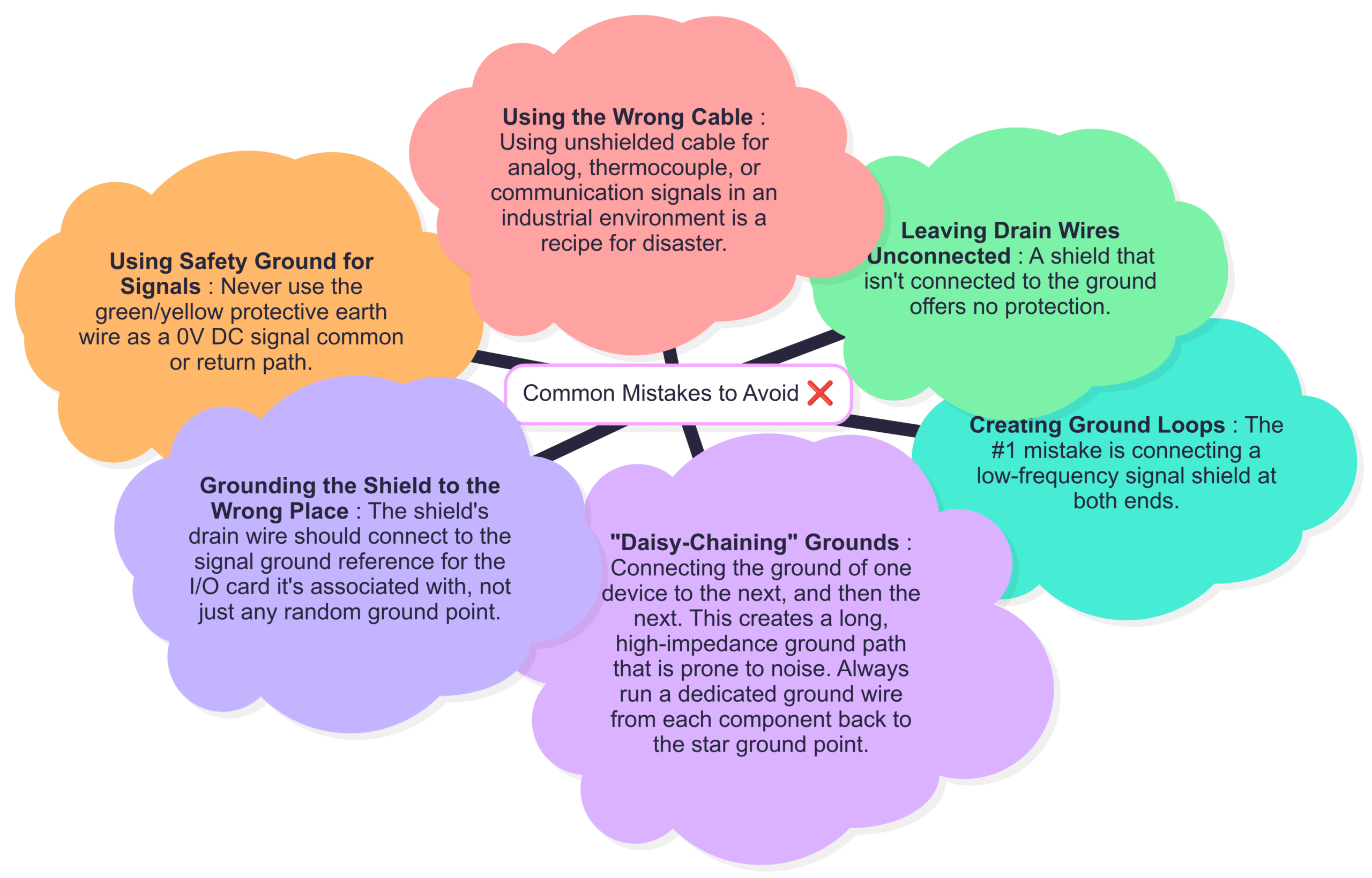
Common Mistakes to Avoid 
-
Creating Ground Loops: The #1 mistake is connecting a low-frequency signal shield at both ends.
-
Using Safety Ground for Signals: Never use the green/yellow protective earth wire as a 0V DC signal common or return path.
-
“Daisy-Chaining” Grounds: Connecting the ground of one device to the next, and then the next. This creates a long, high-impedance ground path that is prone to noise. Always run a dedicated ground wire from each component back to the star ground point.
-
Leaving Drain Wires Unconnected: A shield that isn’t connected to the ground offers no protection.
-
Grounding the Shield to the Wrong Place: The shield’s drain wire should connect to the signal ground reference for the I/O card it’s associated with, not just any random ground point.
-
Using the Wrong Cable: Using unshielded cable for analog, thermocouple, or communication signals in an industrial environment is a recipe for disaster.
Conclusion: An Investment in Reliability
In the complex world of industrial automation, it’s the fundamentals that ensure success. Proper grounding and shielding are not optional extras; they are foundational requirements for a safe, reliable, and robust PLC installation. The initial time and effort spent planning a grounding strategy, selecting the correct shielded cables, and meticulously terminating every connection will pay for itself a hundred times over in reduced downtime, consistent performance, and easier troubleshooting.
By understanding the roles of body earthing for safety and signal earthing for noise immunity—and by implementing a disciplined approach to shielding—you can build a control system that is resilient to the invisible enemy of electrical noise and will operate reliably for years to come.