
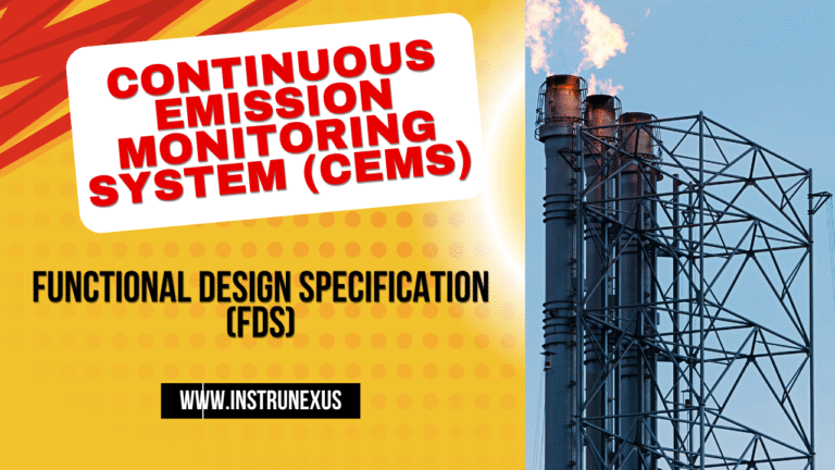
The Ultimate Guide to Functional Design Specification for Continuous Emission Monitoring Systems (CEMS)
In the landscape of modern industry, the imperative to operate sustainably and responsibly has never been more pronounced. At the heart of this responsibility lies the precise measurement and control of industrial emissions. For facilities that release potentially harmful pollutants into the atmosphere, a Continuous Emission Monitoring System (CEMS) is not just a piece of equipment; it is the cornerstone of environmental compliance, operational efficiency, and corporate stewardship. However, the path to a successful CEMS implementation is paved with meticulous planning, and the foundational document for this journey is the Functional Design Specification (FDS).
An FDS for a CEMS is the master blueprint that translates regulatory requirements and process needs into a concrete engineering reality. It defines every facet of the system—from the gas sample probe in the stack to the final report on a regulator’s desk. Without a robust FDS, projects are prone to scope creep, budget overruns, and the ultimate risk of non-compliance.
This guide will provide an in-depth exploration of the critical elements within a CEMS Functional Design Specification, focusing specifically on the measurement of toxic emissions. We will dissect the system’s architecture, functional requirements, performance benchmarks, and data management protocols. Whether you are an environmental manager, a plant engineer, a compliance officer, or a systems integrator, this article will serve as your comprehensive resource for developing an FDS that ensures your CEMS is accurate, reliable, and fully compliant from day one.
Section 1: Defining the Purpose and Scope of a CEMS FDS
Before a single component is ordered or a line of code is written, the purpose and scope of the CEMS must be unequivocally defined within the FDS. This initial stage is crucial for aligning all stakeholders—including plant management, engineering teams, CEMS vendors, and regulatory bodies—on a common set of objectives and boundaries.
The Purpose of a CEMS Functional Design Specification
The FDS serves several fundamental purposes:
A Single Source of Truth: It acts as the definitive document that outlines all technical and functional requirements. This eliminates ambiguity and provides a clear reference point for all project participants, preventing misunderstandings that can lead to costly rework.
A Blueprint for Design and Engineering: The FDS provides the CEMS vendor and system integrators with the precise specifications needed to design, build, and configure the system correctly. It details everything from the choice of analyzer technology to the layout of the user interface.
A Basis for Bidding and Procurement: A detailed FDS allows for accurate and competitive bidding from vendors. When all suppliers are bidding on the same well-defined scope, comparisons are more straightforward, ensuring the facility procures a system that truly meets its needs.
A Benchmark for Validation and Testing: The FDS establishes the specific performance criteria the CEMS must meet. These criteria form the basis for the Factory Acceptance Test (FAT) and the Site Acceptance Test (SAT), providing objective measures for system acceptance.
Defining the Scope of the CEMS
The scope section of the FDS draws the boundaries for the project. It should explicitly detail:
Monitored Sources: Identify the specific industrial processes and emission points (e.g., “Boiler Unit 2 Stack,” “Incinerator Main Stack”) that will be monitored.
Target Pollutants: List every chemical compound and parameter to be measured. For toxic emission monitoring, this is paramount. The list could include:
Criteria Pollutants: Sulfur Dioxide (), Nitrogen Oxides (), Carbon Monoxide ().
Greenhouse Gases: Carbon Dioxide (), Methane ().
Diluent Gases: Oxygen () for correcting concentrations to a standard reference.
Toxic Compounds: Hydrogen Chloride (), Hydrogen Fluoride (), Ammonia (), Mercury (), and Volatile Organic Compounds (VOCs).
System Boundaries: Clearly state the physical and functional limits of the CEMS supply. A typical boundary starts at the sample extraction probe in the stack and ends with the data output from the Data Acquisition and Handling System (DAHS). This includes all interconnecting hardware, software, and utilities.
Applicable Regulations: Cite the specific local, national, and international regulations that govern the CEMS. This includes standards like the U.S. Environmental Protection Agency (EPA) 40 CFR Part 60 and Part 75, or relevant European standards (e.g., EN 14181). These regulations dictate measurement methods, performance specifications, and reporting formats.
By meticulously defining the purpose and scope, the FDS creates a solid foundation, ensuring that the final CEMS installation is fit-for-purpose and meets all operational and regulatory obligations.
Section 2: CEMS System Architecture and Core Components
With the scope defined, the FDS must detail the system’s architecture. The choice of CEMS technology is one of the most critical decisions, as it directly impacts accuracy, maintenance, and long-term cost of ownership, especially when dealing with reactive and corrosive toxic gases.
Choosing the Right CEMS Technology
CEMS technologies are broadly categorized into two types: Extractive and In-Situ.
Extractive CEMS: This is the most prevalent architecture. It involves extracting a sample of the flue gas from the stack, transporting it through a heated sample line, and conditioning it before analysis.
Hot-Wet Extractive: The sample is maintained at a high temperature (above the dew point of the gas stream) all the way to the analyzers. This keeps the gas in its original state, which is crucial for measuring water-soluble gases like and that would otherwise be lost in condensation.
Cold-Dry (Dilution or Full) Extractive: The sample is extracted and then cooled to remove moisture before being sent to the analyzers. While simpler for some gases, this method is generally unsuitable for water-soluble toxic compounds. A dilution system uses a critical orifice to mix a small, precise amount of sample gas with a large volume of clean, dry instrument air, lowering the dew point and eliminating the need for moisture removal.
In-Situ CEMS: In this configuration, the analyzer is installed directly on or within the stack, measuring the gas in its native environment.
Path (Cross-Stack) Analyzers: A beam of light (e.g., infrared or ultraviolet) is sent across the stack duct to a receiver. The absorption of light by the target gases is used to determine their concentration.
Point Analyzers: A probe extends into the stack, and the analysis is performed at a single point within the gas stream.
For measuring a suite of toxic emissions, Hot-Wet Extractive CEMS is often the preferred choice due to its flexibility. It allows for the use of multiple, highly specific analyzers for different compounds and ensures that reactive and soluble gases like and are measured accurately.
Mermaid Block Diagram: Overall CEMS System Architecture (Hot-Wet Extractive)
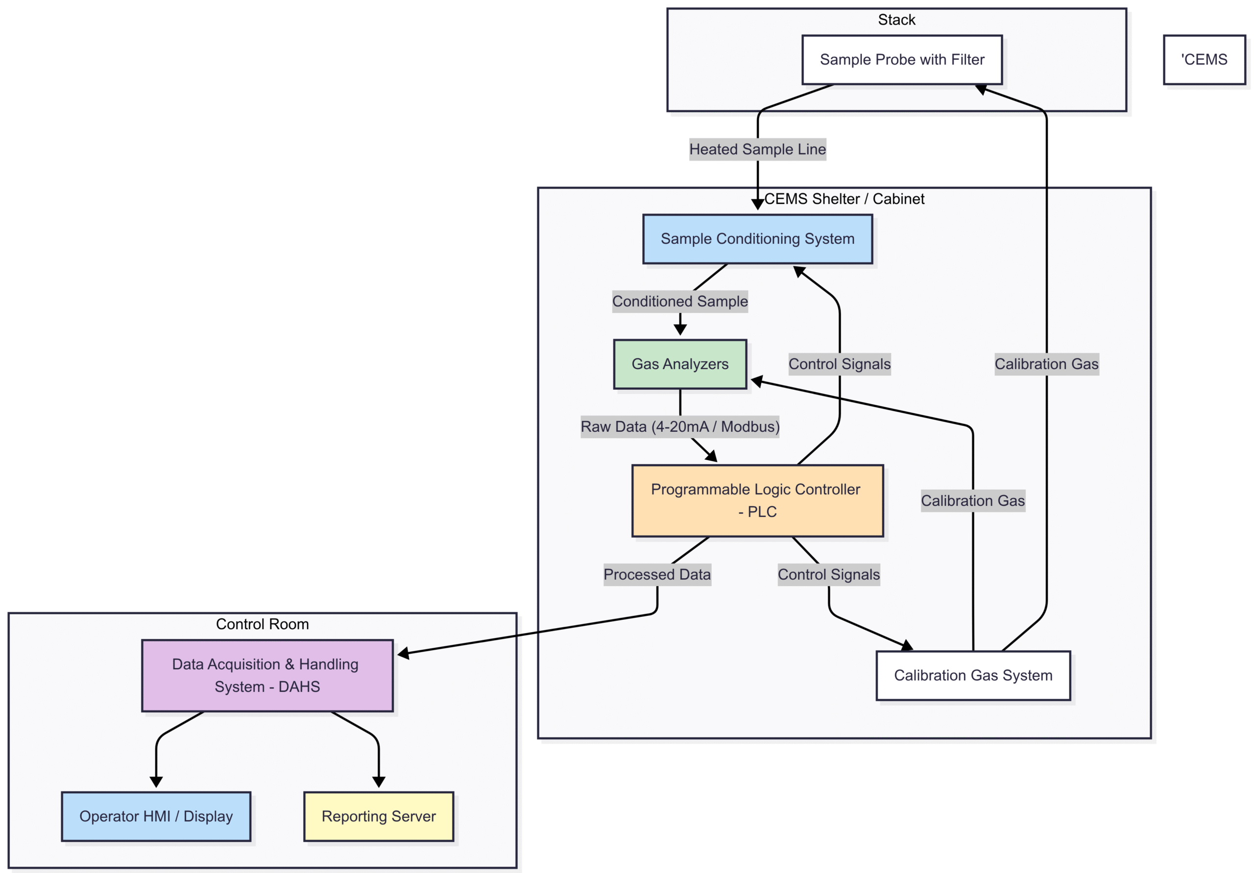
Breakdown of Core CEMS Components
The FDS must provide specifications for each critical component:
Sample Probe: This is the first point of contact with the flue gas. The FDS should specify the material (e.g., Hastelloy C-276 for corrosive environments), length to ensure a representative sample, and the type of filtration needed to remove particulate matter at the source.
Heated Sample Line: For a hot-wet system, this is a critical component. The FDS must define the required temperature (typically >180°C / 356°F), material (e.g., PFA Teflon tubing), and length. It must be electrically heated and temperature-controlled to prevent condensation and sample loss.
Sample Conditioning System (SCS): Even in a hot-wet system, some conditioning is required. This may include additional fine particulate filters or flow control elements. For a cold-dry system, this is a major subsystem involving chillers (coolers) and peristaltic pumps to remove condensate. The FDS must detail the performance requirements of the SCS.
Gas Analyzers: This is the heart of the CEMS. The FDS must specify the analytical principle for each measured gas to ensure specificity and avoid cross-interference. Common technologies include:
Non-Dispersive Infrared (NDIR): For , , .
Chemiluminescence: For .
Zirconia Oxide or Paramagnetic: For .
Tunable Diode Laser Absorption Spectroscopy (TDLAS): Highly specific and sensitive, ideal for toxic gases like , , and .
Cold Vapor Atomic Fluorescence Spectroscopy (CVAFS): For Mercury ().
Calibration Gas System: To meet regulatory requirements for daily checks and quality assurance, the CEMS must have an automated system for introducing certified calibration gases. The FDS should specify the gases required, their concentrations (zero and span points), and the control logic for automated calibration sequences.
Data Acquisition and Handling System (DAHS): The brain of the CEMS. It collects data, performs calculations, and generates reports. This will be discussed in more detail in a later section.
Section 3: Defining the Functional Requirements of a CEMS
This section of the FDS moves from the “what it is” to the “what it does.” It details the specific functions the CEMS must perform to meet operational and regulatory demands.
Measurement Requirements
This is the most fundamental set of requirements. The FDS must clearly state:
Measurement Ranges: For each pollutant, define the expected normal operating range and the maximum range the analyzer must be capable of measuring (e.g., : 0-15 ppm, : 0-200 mg/m³). This ensures the analyzer is accurate during normal operation but can also capture data during process upsets.
Units of Measurement: Specify the units for concentration (e.g., ppm, mg/Nm³) and mass emission rate (e.g., kg/hr, lbs/day). The “N” in mg/Nm³ signifies “Normalised” conditions (e.g., 0°C, 101.3 kPa, dry gas, reference level), and the FDS must define these conditions.
Calculations: The FDS must define all required calculations. This includes the formula for correcting measured concentrations to reference levels and the formula for converting concentrations into mass emission rates using flue gas flow data (which may come from a separate flow monitor).
Operational Requirements
A CEMS must operate reliably with minimal human intervention. The FDS should specify:
Availability/Uptime: Define the required system availability, typically >95% on a quarterly or annual basis, excluding scheduled maintenance.
Automation: The system must perform key quality assurance functions automatically, without operator intervention. This includes:
Daily Zero and Span Drifts Checks: The system should automatically inject zero gas (e.g., nitrogen) and a high-level span gas to check for calibration drift.
Probe Blowback/Purge: The sample probe must be periodically purged with compressed air or nitrogen to prevent clogging. The FDS should define the frequency and duration of these purges.
Alarming and Diagnostics: The FDS must list all conditions that should trigger an alarm. These include:
High emission exceedances (e.g., Level 1 and Level 2 alarms).
CEMS component malfunction (e.g., “Heated Line Temperature Low,” “Analyzer Fault,” “Calibration Gas Pressure Low”).
Maintenance alerts (e.g., “Filter Replacement Due”).
Communication failures.
User Interface (HMI): Define what operators need to see on the local HMI, such as real-time gas concentrations, system status, active alarms, and historical trends.
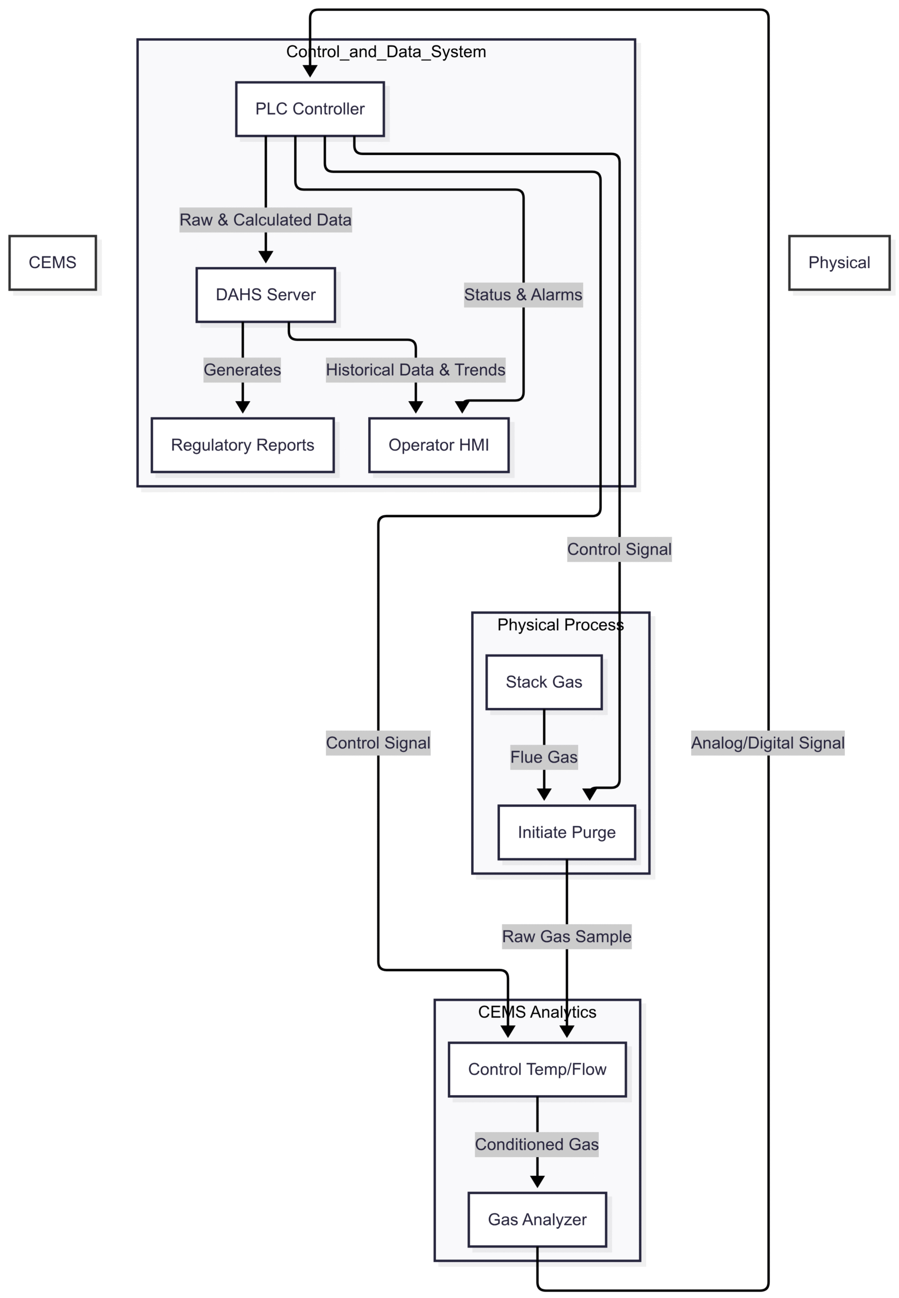
Diagram: CEMS Data and Control Flow
This diagram illustrates the logic loop within the CEMS, from physical measurement to control actions.
Data Acquisition and Reporting Requirements
Data Logging: Specify the primary averaging period for data collection (e.g., 1-minute averages).
Averaging: Define the required output averages for compliance reporting (e.g., 30-minute, 1-hour, 24-hour rolling averages).
Data Storage: State the data retention requirements (e.g., all 1-minute and calculated averages must be stored securely for at least 5 years).
Reporting: The FDS must detail the exact format of all required reports. This may involve providing a template of the report required by the local environmental agency, showing daily averages, exceedance events, and CEMS uptime statistics.
Section 4: Performance Specifications and Acceptance Criteria
This section is the litmus test for the CEMS. It defines “how good” the system needs to be and sets the objective criteria for formal acceptance. These specifications are typically derived directly from regulatory standards like the EPA Performance Specifications (PS).
Key Performance Indicators (KPIs)
The FDS must quantify the required performance:
Relative Accuracy (RA): This is the most critical performance metric. It measures the closeness of the CEMS measurements to a series of reference method tests conducted by an independent third party. The FDS will specify the maximum allowable RA, for example, “The Relative Accuracy as determined by a Relative Accuracy Test Audit (RATA) must be ≤ 7.5% of the reference method value” per EPA PS-2.
Calibration Drift: Measures the stability of the analyzer over time. The FDS will specify the maximum allowable drift for a 24-hour period (e.g., ≤ 2.5% of the span value) and a 7-day period.
Response Time: Defines how quickly the CEMS can detect and display a change in gas concentration, from the probe tip to the final DAHS output. A typical requirement might be ≤ 200 seconds to achieve 95% of a step change.
Linearity Check: Ensures the analyzer is accurate across its entire measurement range. The FDS will specify that the analyzer’s response to multiple calibration gases (e.g., at 0%, 20%, 40%, 60%, 80% of the span) must be within a certain tolerance (e.g., ≤ 5.0% of the span value).
System Bias: A check to ensure the CEMS does not have a systematic error (i.e., it doesn’t consistently read high or low). This is checked during the RATA and must be within a specified limit (e.g., ≤ 4.0% of the span).
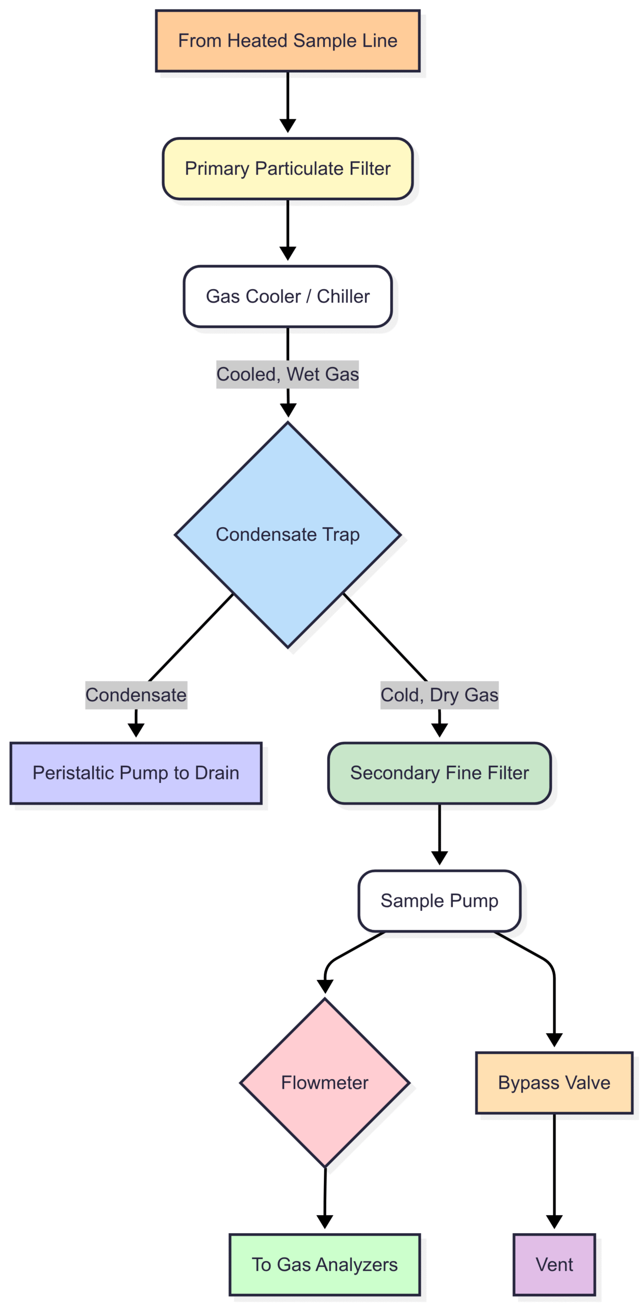
Mermaid Block Diagram: Sample Conditioning System (Cold-Dry Extractive)
While hot-wet is often preferred for toxics, a cold-dry system is common for other gases. Its complexity warrants a detailed diagram in an FDS.
Factory Acceptance Test (FAT) and Site Acceptance Test (SAT)
The FDS must outline the procedures for accepting the system.
Factory Acceptance Test (FAT): Performed at the vendor’s facility before shipment. The FDS should state that the FAT will include a full functional check of all hardware and software, a simulated run of all alarms, and a verification of the automated calibration sequence.
Site Acceptance Test (SAT): Performed after the CEMS is installed and commissioned on-site. The SAT is more comprehensive and includes:
Verification of all FDS functional requirements.
A successful 7-day calibration drift test.
A successful initial Relative Accuracy Test Audit (RATA) witnessed by relevant parties.
The system is not formally handed over until all SAT criteria specified in the FDS are met.
Section 5: Data Acquisition and Handling System (DAHS) in Detail
The DAHS (or DAS) is the central nervous system of the CEMS. The FDS must provide detailed specifications for its hardware, software, and functionality.
Core DAHS Functions
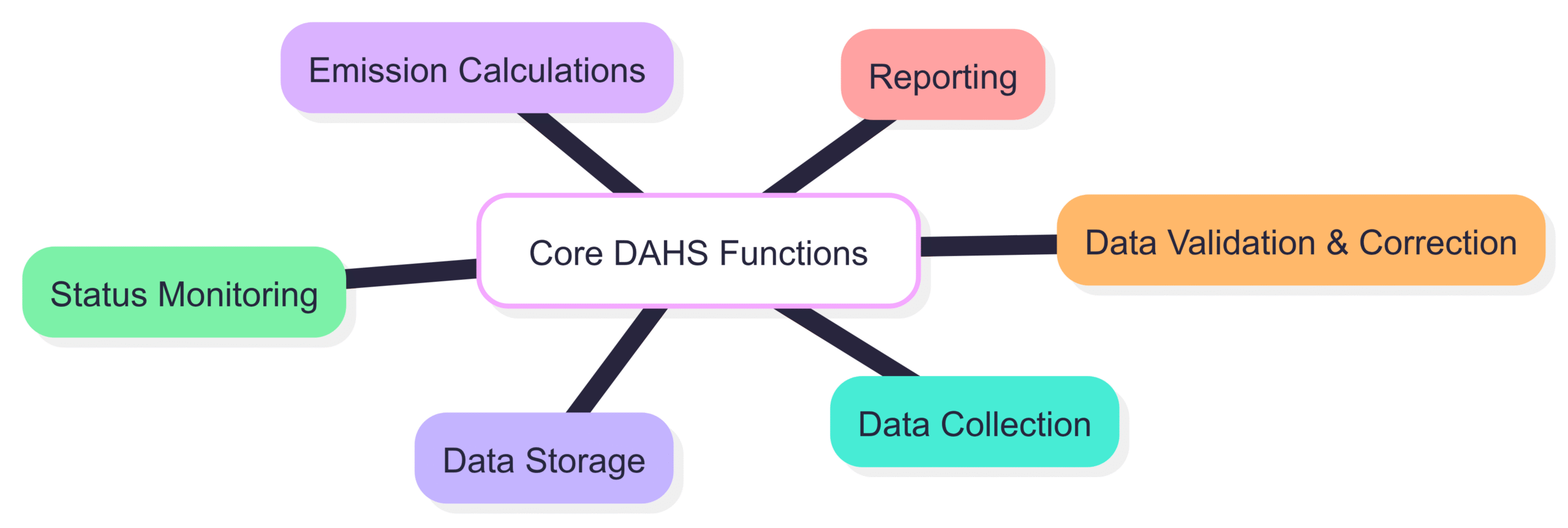
The FDS must mandate that the DAHS performs the following functions seamlessly:
Data Collection: Interface with all analyzers and process instruments (e.g., stack flow meter, temperature/pressure sensors) via specified protocols (e.g., Modbus, 4-20mA analog signals).
Data Validation & Correction: Perform real-time validation checks (e.g., is the data within a valid range?) and apply all necessary corrections (e.g., moisture, temperature, pressure, normalization).
Emission Calculations: Continuously calculate all required averages (e.g., 1-hour, 24-hour) and mass emission rates as defined in the functional requirements.
Status Monitoring: Monitor the health of the entire CEMS, flagging any maintenance needs or fault conditions.
Data Storage: Log and archive all raw and calculated data in a secure, tamper-proof database. The FDS should specify the database technology and backup procedures.
Reporting: Automatically generate all required environmental compliance reports in the exact format stipulated by the governing agency. It should also provide tools for ad-hoc report generation and data analysis.
Hardware and Software Specifications
Hardware: The FDS should specify the type of controller (e.g., a robust industrial PLC is often preferred over a standard PC for control reliability) and the server hardware for the DAHS software. It should also specify requirements for uninterruptible power supplies (UPS).
Software: The software must be robust, reliable, and secure. For many industries, compliance with data integrity standards like 21 CFR Part 11 is crucial. This requires features like secure user access control, audit trails that log all actions and changes, and electronic signatures.
Communication: Define all communication protocols. For example, the analyzers might communicate with the PLC via Modbus TCP/IP, and the PLC might send data to the plant’s Distributed Control System (DCS) via OPC (Open Platform Communications).
Section 6: Safety, Maintenance, and Documentation
A complete FDS also addresses the long-term operational aspects of the system.
Safety Requirements: This section details safety protocols for system operation and maintenance. It includes specifications for the safe storage and handling of high-pressure calibration gas cylinders, adherence to electrical safety codes (e.g., NEC, ATEX for hazardous areas), and lock-out/tag-out procedures.
Maintenance Requirements: To ensure the >95% uptime, the FDS must define the required preventive maintenance (PM) schedule. It should request that the vendor provide a detailed PM plan (daily, weekly, monthly, quarterly, and annual tasks) and a recommended spare parts list.
Documentation: The FDS must specify the full set of documentation to be delivered with the system. This comprehensive package should include:
The final (“as-built”) Functional Design Specification.
Detailed engineering drawings (P&ID, electrical schematics, cabinet layouts).
Operation and Maintenance (O&M) manuals for all components.
Software manuals and license information.
Calibration procedures and certificates for all analyzers and gases.
FAT and SAT reports.
Conclusion
A Continuous Emission Monitoring System is a significant investment and a critical asset for ensuring environmental compliance. Its success or failure is often determined long before the hardware arrives on site. A comprehensive, detailed, and well-written Functional Design Specification is the single most important factor in a successful CEMS project.
By meticulously defining the system’s scope, architecture, functional requirements, performance specifications, and data handling protocols, the FDS serves as the guiding star for all stakeholders. It mitigates risk, ensures regulatory adherence, and provides a clear roadmap for delivering a system that is reliable, accurate, and defensible. Investing the time and expertise to create a robust FDS is not just good engineering practice; it is the foundation of long-term environmental and operational excellence.
If you are embarking on a CEMS project, ensure it starts on the right foundation. Contact our CEMS experts today to help you develop a Functional Design Specification that guarantees success.