
Understanding Functional Safety
This application translates the complex IEC 61511 standard into an accessible, interactive experience. Explore the core principles of functional safety, understand how risk is quantified, and use the interactive tool to determine Safety Integrity Levels (SIL) for your own scenarios. Start by exploring the foundational concepts below.
Safety Instrumented System (SIS)
An independent layer of protection.
Safety Instrumented Function (SIF)
A specific protective action.
Safety Integrity Level (SIL)
A measure of reliability.
SIL and Risk Reduction
The Risk Reduction Factor (RRF) is a key metric. It represents how much a SIF reduces the frequency of a hazardous event. This chart shows the minimum RRF required for each SIL level, illustrating the exponential increase in performance.
The Risk Assessment Framework
Before calculating a SIL, we must establish a framework for evaluating risk. This involves defining what level of risk is tolerable (the ALARP principle) and creating clear, consistent scales for the two dimensions of risk: the severity of the consequence and the likelihood of the event.
The ALARP Principle
Risk Dimensions
Interact with the tabs below to explore the defined categories for Consequence and Likelihood. These form the axes of the risk matrix.
Consequence Severity
Likelihood of Occurrence
Interactive SIL Calculator
Apply the risk framework using this tool. First, select the consequence and likelihood for your hazardous scenario. The tool will calculate the required SIL based on the pre-calibrated matrix. You can also interact directly with the matrix to see how different risk combinations map to SIL ratings.
1. Select Scenario Parameters
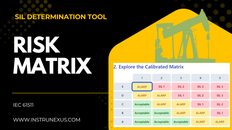
2. Explore the Calibrated Matrix
The IEC 61511 Safety Lifecycle
SIL determination is not an isolated activity; it's a critical, mandatory phase within a larger, systematic engineering process. The safety lifecycle provides a framework for managing a Safety Instrumented System from concept to decommissioning, ensuring that risks are controlled throughout.
Hazard and Risk Assessment
Identify potential hazards and analyze their risks using methods like Process Hazard Analysis (PHA) or HAZOP.
SIL Determination (This Application's Focus)
For each hazard requiring a SIF, determine the target SIL by comparing the unmitigated risk against tolerable risk criteria using a risk matrix.
Safety Requirements Specification (SRS)
Create a detailed design brief for the SIF, specifying the target SIL, functionality, response times, and testing requirements.
Design, Engineering, and SIL Verification
Design the SIF with specific components and perform calculations (SIL verification) to prove the design meets the target SIL.
Operation, Maintenance, and Testing
Operate the SIF, perform regular proof tests to detect hidden failures, and manage any modifications through a formal process.
A Comprehensive Guide to SIL Determination using a Risk Matrix in Accordance with IEC 61511
Section 1: Foundations of Functional Safety and the IEC 61511 Standard
The management of hazardous processes in industries such as oil and gas, chemical processing, and power generation demands a systematic and rigorous approach to safety. Functional safety represents a critical discipline within this domain, focusing on the active systems designed to prevent or mitigate catastrophic events. This section establishes the foundational principles, terminology, and regulatory context, primarily centered on the international standard IEC 61511, that govern the design and implementation of these vital safety systems.
1.1 Introduction to Functional Safety
Functional safety is the part of the overall safety of a system or piece of equipment that depends on that system or equipment operating correctly in response to its inputs. It is concerned with active safety measures that automatically bring a process to a safe state when predetermined conditions are violated, thereby preventing or mitigating hazardous events.
The cornerstone of functional safety is the international standard IEC 61508, which provides a generic framework for the functional safety of electrical, electronic, and programmable electronic (E/E/PE) safety-related systems. Recognizing that different industries have unique requirements, several sector-specific standards have been derived from this foundational document. For the process industry, the definitive standard is IEC 61511, titled “Functional safety – Safety instrumented systems for the process industry sector”. This standard is considered the benchmark and recognized good engineering practice for ensuring the safety of industrial processes through instrumentation. It provides a comprehensive methodology for the design, implementation, and maintenance of Safety Instrumented Systems (SIS) throughout their entire lifecycle.
1.2 Core Terminology: SIS, SIF, and the Process Hazard
A clear understanding of the core terminology is essential for navigating the requirements of IEC 61511.
-
Safety Instrumented System (SIS): An SIS is an engineered system used to implement one or more Safety Instrumented Functions. It is composed of a separate and independent combination of sensors, logic solvers, and final elements designed and managed to achieve a specified level of safety performance. The SIS acts as a critical layer of protection, independent of the basic process control system (BPCS).
-
-
Safety Instrumented Function (SIF): A SIF is a specific safety function implemented within the SIS to protect against a particular hazard. For example, a SIF might be designed to detect a high pressure in a vessel (sensor), process the logic that this condition is dangerous (logic solver), and automatically close an inlet valve to stop the flow (final element). Each SIF is assigned a target Safety Integrity Level (SIL) based on the amount of risk reduction it is required to provide.
-
-
Process Hazard Analysis (PHA): The journey of functional safety begins with a Process Hazard Analysis (PHA). This is a systematic effort to identify and analyze the significance of potential hazards associated with the processing of hazardous materials. Methodologies such as Hazard and Operability (HAZOP) studies are employed by multi-disciplinary teams to systematically scrutinize a process design and identify potential deviations from normal operation that could lead to hazardous events, often termed “Loss of Containment” (LOC) scenarios. The documented output from a PHA, which includes identified hazards, their causes, consequences, and existing safeguards, serves as the critical input for the SIL determination process.
1.3 The IEC 61511 Safety Lifecycle
The IEC 61511 standard is structured around a safety lifecycle, which provides a comprehensive and systematic engineering process for all activities involved in the implementation of an SIS, from initial concept to final decommissioning. SIL determination is a mandatory and distinct phase within this lifecycle, occurring after the initial hazard and risk assessment.
The lifecycle is not merely a technical checklist; it is a management framework designed to control and minimize systematic failures. While random hardware failures can be quantified and managed through probabilistic calculations, systematic failures—which arise from human error in specification, design, implementation, or maintenance—cannot. These failures are controlled by adhering to a rigorous, documented process that includes defined roles and responsibilities, competency management, verification activities, and independent functional safety assessments. The structured nature of the safety lifecycle is the primary defense against these insidious and often unquantifiable errors. A perfectly calculated SIL for a SIF is rendered meaningless if the lifecycle processes, such as the creation of a clear Safety Requirements Specification (SRS) or the formal management of modifications, are not rigorously followed.
Furthermore, the modern industrial landscape has introduced new threats. The 2016 revision of IEC 61511 formally acknowledged this by mandating that a cybersecurity risk assessment be performed to identify the security vulnerabilities of the SIS. Modern SIS are predominantly based on programmable electronic systems, which are inherently vulnerable to cyber-attacks. A malicious actor could potentially trigger a hazardous event or, more likely, disable the very safety functions designed to protect against it. Consequently, a traditional PHA that considers only process-related failures (e.g., a pump failure) is no longer sufficient. The safety lifecycle now requires the consideration of intentional, malicious acts alongside random hardware failures and systematic human errors. This integration signifies that functional safety and cybersecurity are no longer separate disciplines but are deeply intertwined in the protection of modern industrial processes.
Section 2: Understanding Safety Integrity Levels (SIL)
Safety Integrity Level (SIL) is the central concept in the performance-based approach of IEC 61511. It provides a standardized, quantifiable measure of the reliability required of a safety function. This section decodes the SIL concept, linking it to concrete engineering metrics and clarifying common misconceptions.
2.1 Defining SIL
SIL is a discrete level, ranging from 1 to 4, used to specify the target level of risk reduction provided by a Safety Instrumented Function (SIF). A higher SIL indicates a greater required risk reduction, a more reliable safety function, and a lower probability that the SIF will fail to perform its designated safety action when a demand occurs. SIL 1 represents the lowest level of safety integrity, while SIL 4 represents the highest. In the process industries, SIL 4 functions are exceptionally rare, as a process requiring such a high level of instrumented protection is often considered to have a fundamentally unsafe design that should be addressed through inherent safety measures.
2.2 The Quantitative Basis of SIL: PFD and RRF
The SIL level is not an arbitrary label; it is defined by a specific range of performance metrics. For the process industry, SIFs typically operate in a “low-demand” mode, meaning they are called upon to act infrequently (less than once per year). In this mode, the key performance metrics are the Probability of Failure on Demand (PFD) and the Risk Reduction Factor (RRF).
-
Probability of Failure on Demand (PFD): The PFD (or more accurately, PFDavg, the average probability of failure on demand over the proof-test interval) is the probability that a SIF will fail to perform its safety function when a demand occurs. For example, a PFD of 0.01 means there is a 1% chance the SIF will fail when needed.
-
-
Risk Reduction Factor (RRF): The RRF is the mathematical inverse of the PFDavg (RRF=1/PFDavg). This metric is often more intuitive for risk assessment teams. An RRF of 100 means the SIF reduces the frequency of the hazardous event by a factor of 100.
For the less common case of SIFs operating in “high-demand” or “continuous” mode (where demands occur more frequently than once per year), the performance metric is the Probability of a dangerous Failure per Hour (PFH). The relationship between these metrics and SIL is standardized, as shown in Table 1.
Table 1: SIL Quantitative Definitions
| SIL Level | PFDavg (Low Demand Mode) | RRF (Low Demand Mode) | PFH (High Demand/Continuous Mode) (h−1) |
| SIL 1 | ≥10−2 to <10−1 | ≥10 to <100 | ≥10−6 to <10−5 |
| SIL 2 | ≥10−3 to <10−2 | ≥100 to <1,000 | ≥10−7 to <10−6 |
| SIL 3 | ≥10−4 to <10−3 | ≥1,000 to <10,000 | ≥10−8 to <10−7 |
| SIL 4 | ≥10−5 to <10−4 | ≥10,000 to <100,000 | ≥10−9 to <10−8 |
This table is the fundamental link between the risk assessment process, which determines the required RRF, and the subsequent engineering design, which must meet the corresponding PFDavg target.
2.3 A Critical Clarification: SIL Applies to Functions, Not Components
A pervasive and dangerous misconception in the industry is the idea that individual components, such as a pressure transmitter or a valve, can be “SIL-rated.” This is incorrect. As the standards make clear, SIL levels apply to entire Safety Instrumented Functions (SIFs) and the Safety Instrumented Systems (SIS) that implement them.
A SIF is a complete safety loop, comprising sensors, a logic solver, and final elements. The overall PFDavg of this function depends on the failure rates of
all its constituent parts, the architectural configuration (e.g., redundancy like 1-out-of-2 or 2-out-of-3 voting), the frequency and effectiveness of proof testing, and the systematic capability of the components. A single component, therefore, cannot have a SIL rating in isolation.
Component manufacturers can, and do, have their devices certified according to IEC 61508 as being “suitable for use in SIL X applications.” This certification signifies that the manufacturer has followed a rigorous development process to control systematic failures and can provide the necessary reliability data (e.g., failure rates for safe and dangerous modes) required for an end-user to perform SIL verification calculations. However, this is not a SIL rating for the component itself. An engineer cannot procure three “SIL 2 suitable” components and assume they have created a SIL 2 SIF. A detailed calculation for the entire SIF loop must be performed to verify that the PFDavg target for the desired SIL is met. This distinction is crucial for preventing a false sense of security and ensuring genuine compliance.
Section 3: The Principle of Tolerable Risk and ALARP
Before a SIL can be determined for a safety function, a fundamental question must be answered: “How safe is safe enough?” The answer to this question is formalized through the concepts of tolerable risk and the ALARP principle, which provide the philosophical and ethical foundation for setting safety targets.
3.1 Defining Risk Tolerance
Every organization operating hazardous facilities must establish and document its criteria for tolerable risk. This is not a universal constant; it is a specific policy based on corporate philosophy, national legal and regulatory requirements, insurance stipulations, and societal expectations. The risk tolerance criteria define the boundary between acceptable and unacceptable risks.
The process of SIL determination involves comparing the unmitigated risk of a hazardous scenario (i.e., the risk without the SIF being considered) against these corporate tolerable risk criteria. If the existing risk is higher than the tolerable level, a “risk gap” exists. The purpose of the SIF is to provide the necessary risk reduction to close this gap and bring the residual risk down to a tolerable level.
3.2 The ALARP Principle: As Low As Reasonably Practicable
In many regulatory regimes, particularly those influenced by the UK Health and Safety Executive (HSE), the concept of tolerable risk is governed by the ALARP principle, which stands for “As Low As Reasonably Practicable”. The ALARP principle states that risks must be reduced until the “sacrifice” (in terms of cost, time, and effort) required to achieve further risk reduction becomes “grossly disproportionate” to the safety benefit gained.
This principle is often visualized using a triangle that divides risk into three distinct regions :
-
Unacceptable Region: At the top of the triangle, the risk is so high that it cannot be justified under normal circumstances. The activity must be modified to reduce the risk, regardless of cost.
-
Tolerable Region (or ALARP Region): This is the middle section where risks are tolerated only if all reasonably practicable measures have been taken to reduce them. It is within this region that cost-benefit analysis is applied to determine if further safety measures are required.
-
Broadly Acceptable Region: At the bottom of the triangle, the risk is considered negligible and is comparable to the everyday risks people accept. No further risk reduction is required.
3.3 ALARP in Practice
Demonstrating that a risk has been reduced to ALARP is not a simple declaration; it is a formal, documented process. It requires the systematic identification and evaluation of potential risk reduction measures. Crucially, the documentation must justify not only the safety measures that were implemented but also those that were considered and rejected, explaining why they were not reasonably practicable. In many legal frameworks, the burden of proof rests on the operator to demonstrate that they have taken all reasonably practicable steps to ensure safety.
It is essential to recognize that ALARP is a dynamic concept, not a static target. What is considered “reasonably practicable” is dependent on current technology, industry knowledge, and societal values. A safety measure that was prohibitively expensive or technologically unfeasible a decade ago may be considered standard practice today. This implies that an organization’s ALARP demonstration is a living document. The safety lifecycle’s requirements for periodic risk assessments and formal management of change are the mechanisms that ensure risks are continually managed to remain ALARP throughout the operational life of a facility. This may even necessitate the recalibration of the risk matrix itself over time to reflect these evolving standards.
Section 4: Architecting the SIL Determination Risk Matrix
The risk matrix is a semi-quantitative tool that allows a team to systematically and consistently apply an organization’s risk tolerance criteria to determine the required SIL for a SIF. While IEC 61511 does not mandate a specific method, the risk matrix is a widely used and accepted approach. Its validity, however, depends entirely on a rigorous and transparent process of defining its axes and calibrating its cells.
4.1 Defining Consequence Categories (The Y-Axis)
The first step in building a risk matrix is to establish a clear and unambiguous scale for the severity of potential consequences. This scale must be defined and agreed upon by the organization’s stakeholders before any assessment begins to ensure consistency. A robust consequence scale is multi-faceted, considering the potential impact on three key areas: personnel safety, environmental damage, and asset or financial loss. An example of a well-defined, five-level consequence scale is provided in Table 2.
Table 2: Example Consequence Category Definitions
| Level | Severity Name | Personnel Safety Impact | Environmental Impact | Asset / Financial Impact |
| 5 | Catastrophic | Multiple fatalities | Major, long-term environmental damage; extensive remediation required; national media attention. | Loss greater than $10,000,000. |
| 4 | Major | Single fatality or permanent disabling injuries. | Significant environmental damage; reportable to national agency; local media attention. | Loss between $1,000,000 and $10,000,000. |
| 3 | Serious | Serious, non-disabling injury (e.g., lost time injury). | Moderate environmental damage; reportable to local agency; contained on-site. | Loss between $100,000 and $1,000,000. |
| 2 | Minor | Minor injury requiring first aid or medical treatment case. | Minor, localized environmental impact; no reporting required. | Loss less than $100,000. |
| 1 | Negligible | No injury or adverse health effects. | No detectable environmental impact. | Negligible financial impact. |
4.2 Defining Likelihood Categories (The X-Axis)
In parallel, a scale must be developed for the likelihood of the hazardous event occurring, assuming no SIF is in place. This is the initiating event frequency. To make the matrix a semi-quantitative tool, it is critical that each qualitative descriptor (e.g., “Occasional”) is explicitly linked to a quantitative frequency range. Table 3 provides an example of such a scale.
Table 3: Example Likelihood Category Definitions
| Level | Likelihood Name | Qualitative Description | Quantitative Frequency (events per year) |
| E | Frequent | Has occurred several times at the facility or is expected to occur several times during the facility’s life. | >10−2 (> 1 in 100 years) |
| D | Occasional | Has occurred at the facility or frequently in the industry. | 10−3 to 10−2 (1 in 100 to 1 in 1,000 years) |
| C | Unlikely | Has occurred in the industry but is not common. | 10−4 to 10−3 (1 in 1,000 to 1 in 10,000 years) |
| B | Remote | Has a remote chance of happening; unheard of at the facility but has occurred in the industry. | 10−5 to 10−4 (1 in 10,000 to 1 in 100,000 years) |
| A | Improbable | Has a very remote chance of happening; practically impossible. | <10−5 (< 1 in 100,000 years) |
4.3 Calibrating the Matrix: Mapping Risk to SIL and ALARP Zones
Calibration is the most critical step in creating a defensible risk matrix. It is the process of populating the cells of the matrix based on the organization’s defined tolerable risk targets for each consequence level. This transforms the matrix from a purely qualitative tool into a semi-quantitative one that directly reflects corporate safety policy.
The calibration process follows this logic for each cell:
-
Identify the Tolerable Risk Frequency: The organization must define its tolerable risk frequency (TRF) for each consequence level. For example, the TRF for a “Major” consequence (single fatality) might be set at 10−4 events per year (1 in 10,000 years), in line with guidance from some regulatory bodies.
-
Calculate the Required Risk Reduction: For a given cell at the intersection of a likelihood and a consequence, the required Risk Reduction Factor (RRF) is calculated as: RRF=Tolerable Risk Frequency Likelihood Frequency
-
-
Map RRF to SIL: The calculated RRF is then mapped to the corresponding SIL using the standard definitions in Table 1.
Worked Example:
-
Scenario: A hazard with a “Major” consequence (Level 4).
-
Likelihood: The initiating event likelihood is “Occasional” (Level D, midpoint frequency of 10−2.5 or ~1 in 316 years).
-
Tolerable Risk: The company’s TRF for a “Major” consequence is 10−4 events/year.
-
Calculation: RRF=10−410−2.5=101.5≈31.6
-
-
SIL Mapping: An RRF of 31.6 falls within the range of 10 to 100. Therefore, the required SIL is SIL 1. The cell at the intersection of [Major Consequence] and [Occasional Likelihood] is populated with “SIL 1”.
This process is repeated for every cell. The ALARP regions are then overlaid. Combinations resulting in a risk far above the tolerable level are colored Red (Unacceptable). Those close to or just above the tolerable level, requiring a SIF, are colored Yellow (Tolerable/ALARP). Those already below the tolerable level are colored Green (Broadly Acceptable).
Table 4: Example Calibrated Risk Matrix
| Likelihood | 1 – Negligible | 2 – Minor | 3 – Serious | 4 – Major | 5 – Catastrophic |
| E – Frequent | ALARP | SIL 1 | SIL 2 | SIL 3 | SIL 3 |
| D – Occasional | ALARP | ALARP | SIL 1 | SIL 2 | SIL 3 |
| C – Unlikely | Acceptable | ALARP | ALARP | SIL 1 | SIL 2 |
| B – Remote | Acceptable | Acceptable | ALARP | ALARP | SIL 1 |
| A – Improbable | Acceptable | Acceptable | Acceptable | ALARP | ALARP |
-
Color Key:
-
Red (e.g., SIL 3 cells): Unacceptable Risk
-
Yellow (e.g., SIL 1, SIL 2, ALARP cells): Tolerable if ALARP
-
Green (e.g., Acceptable cells): Broadly Acceptable Risk
-
-
-
-
It is important to clarify the distinction between a risk matrix and a risk graph. While the terms are sometimes used interchangeably 1 , they are technically different methods described in IEC 61511-3. 2 A risk matrix, as presented here, is a two-dimensional grid of Likelihood vs. Consequence. A risk graph is a more complex, decision-tree-like tool that incorporates additional modifying parameters such as Frequency of Exposure (F) and Possibility of Avoidance (P). 3 The HTML tool provided in this report implements the more common and straightforward 2D risk matrix.