
Protecting the Heart of Industry
An interactive exploration of compressor anti-surge control systems. Discover the dynamics of aerodynamic surge, the sophisticated technologies designed to prevent it, and the critical knowledge required to ensure the safety and efficiency of vital industrial assets.
The Problem: Understanding Compressor Surge
Compressor surge is not a simple malfunction; it's a violent, system-wide aerodynamic instability with potentially catastrophic consequences. This section explores what surge is, why it happens, and the severe impact it can have on machinery, production, and safety.
What is Surge? A Violent Flow Reversal
Surge is a cyclic phenomenon. When a compressor cannot overcome downstream pressure, the flow of gas breaks down, stops, and violently reverses direction. This depressurizes the system, allowing forward flow to resume until the cycle repeats, often at a low, damaging frequency.
Key Triggers
- ➤**Process Changes:** Sudden drop in downstream demand or a line blockage.
- ➤**Operational Changes:** Rapid reduction in driver speed.
- ➤**Mechanical Degradation:** Fouling or damage to internal components.
Severe Consequences
Mechanical Damage
Extreme axial thrust destroys bearings, high pressure pulsations damage seals, and aerodynamic forces can cause catastrophic impeller failure.
Process Disruption
A surge event almost always leads to a compressor trip and shutdown, causing immediate production loss and potential plant-wide upsets.
Safety Hazards
In hazardous gas service, seal failure can lead to leaks, creating a risk of fire, explosion, or toxic exposure to personnel and the environment.
The Solution: Proactive Anti-Surge Control
Anti-Surge Control (ASC) is a dedicated, high-speed safety system. Its sole purpose is to preemptively detect when a compressor is approaching an unstable condition and take immediate corrective action to keep it operating safely, balancing protection with efficiency.
The Compressor Performance Map
This map is the battlefield. The ASC system continuously tracks the compressor's operating point (pressure vs. flow) and ensures it never crosses the Surge Limit Line (SLL) into the unstable region. It does this by controlling to a safer Surge Control Line (SCL), providing a critical safety margin.
Industry Landscape: Technology Providers
The market for anti-surge technology features specialized experts and major automation providers, each with a distinct philosophy. The choice between a dedicated, purpose-built controller and a system integrated into the plant-wide DCS is a key strategic decision.
Multi-Compressor Control: The Art of Load Sharing
When multiple compressors run in parallel, uncoordinated control is inefficient and dangerous. Modern load sharing doesn't just split the work; it equalizes the *risk* of surge across all machines, creating a single, cohesive, and highly resilient system.
The Principle: Equidistant from Surge
The goal is to dynamically adjust each compressor's load to maintain an equal operational margin from its respective Surge Control Line. This ensures no single machine is disproportionately vulnerable and maximizes the entire network's ability to handle process upsets without wasteful recycling.
The chart shows the surge margin for two parallel compressors. Notice how uncoordinated control leaves one machine with very little margin (high risk). Coordinated load sharing intelligently balances the load to equalize this margin, making the entire system safer and more efficient.
A Practical Guide for the Instrumentation Engineer
Successful implementation requires a holistic understanding of the entire control loop. This toolkit covers key responsibilities and technical considerations, from initial design to long-term troubleshooting, for the engineers who safeguard these critical assets.
The control loop is only as good as its measurements. Specify modern, fast-response transmitters (pressure, flow, temp) with time constants under 250ms. For critical applications, use redundant transmitters with robust failure detection logic to ensure system integrity.
This is not a standard valve; it's a piece of safety equipment. Key specifications include:
- **Speed:** Must stroke fully open in 1-2 seconds, requiring high-performance actuators and volume boosters.
- **Sizing:** Must be correctly sized to pass enough flow without being unstable near its seat.
- **Fail-Safe:** Must be specified to fail-open on loss of air or signal.
- **Noise Abatement:** Requires specialized low-noise trims to prevent destructive vibration.
Tuning is a high-stakes activity. Use a methodical approach, performing step tests on full recycle to calculate initial PI parameters. The tuning should be asymmetrical: aggressive gain for valve opening (protection) and slower gain for closing (process stability). Always perform thorough pre-commissioning checks on all instruments and the valve itself.
Symptom: Unnecessary Recycling
**Potential Causes:** Incorrect surge line programmed in the controller, faulty/drifting instrumentation giving false readings, or environmental factors affecting controller electronics.
Symptom: Compressor Surges Anyway
**Potential Causes:** The anti-surge valve is not opening fast enough (mechanical issue, failing positioner), controller tuning is too sluggish, or the surge margin (SCL) is set too close to the actual surge line (SLL).
An Engineer’s Comprehensive Guide to Compressor Anti-Surge Control Systems: From Aerodynamic Fundamentals to Advanced Multi-Unit Load Sharing
Section 1: The Dynamics of Compressor Surge
The reliable operation of centrifugal and axial compressors is fundamental to a vast array of industrial processes, from oil and gas production to power generation and chemical manufacturing. However, these critical assets are susceptible to a violent aerodynamic instability known as surge. Before exploring the sophisticated control systems designed to prevent this phenomenon, it is imperative to first establish a thorough understanding of its physical nature, its triggers, and its potentially catastrophic consequences. Surge is not merely a component failure but a complex instability of the entire compression system, demanding a holistic analytical approach.
1.1. Defining Aerodynamic Instability: Flow Reversal and Oscillation
Compressor surge is a form of aerodynamic instability characterized by violent, periodic oscillations in mass flow rate and pressure throughout the compression system. This instability occurs when the compressor, operating at low flow rates or high-pressure ratios, is unable to generate sufficient head to overcome the pressure in the downstream piping and vessels. When this critical point is reached, the forward flow through the compressor momentarily breaks down and reverses direction, causing gas to flow backward from the discharge nozzle toward the suction nozzle.
This flow reversal rapidly depressurizes the discharge system, allowing the compressor to re-establish forward flow. However, if the underlying conditions that caused the initial flow breakdown persist, the compressor will again build pressure until it can no longer overcome the system resistance, and the cycle repeats. This cyclic process of flow reversal and re-establishment is the defining characteristic of surge, often manifesting with audible thumping or honking noises at frequencies as low as 1 Hz.
The severity of the phenomenon can vary. Technical literature distinguishes between mild surge, an instability characterized by pressure and flow oscillations without a full reversal of mass flow, and deep surge, which involves a complete, negative mass flow rate as gas is violently expelled back through the compressor’s inlet. The specific nature of the surge event—whether it is mild or deep, its frequency, and its amplitude—is not solely a function of the compressor itself but is heavily influenced by the physical characteristics of the connected system. The volume of the discharge piping and associated vessels acts as a pneumatic capacitor; larger volumes can store more compressed gas, leading to more energetic and potentially more damaging low-frequency, high-amplitude surge cycles. This systemic nature is a critical concept; one cannot fully analyze or mitigate surge by considering the compressor in isolation from its process environment.
1.2. The Compressor Performance Map: Visualizing the Boundaries of Stable Operation
The operational behavior of a centrifugal or axial compressor is graphically represented by its performance map. This essential engineering tool plots a measure of the pressure increase generated by the compressor (typically the pressure ratio, Rc, or polytropic head, Hp) against the volumetric or mass flow rate through it (Q). The map contains lines of constant rotational speed, efficiency islands, and, most importantly for this discussion, the boundaries of its stable operating envelope.
The critical boundary on the left side of the map is the Surge Limit Line (SLL). The SLL represents the locus of points defining the minimum flow a compressor can sustain at a given pressure ratio before the onset of aerodynamic instability. The region to the right of the SLL is the stable, operable range, while the region to the left is the unstable, surge-prone domain where operation is not possible. The real-time performance of the compressor is represented by its
operating point on this map. The primary objective of any anti-surge control system is to continuously monitor the location of this operating point and ensure it never crosses the SLL into the unstable region.
1.3. Causal Factors: Process, Mechanical, and Control System Triggers
A surge event is triggered when the compressor’s operating point is pushed across the SLL. This can be caused by a wide range of factors, which can be categorized as follows:
-
Process-Induced Causes: These are the most common triggers and relate to changes in the downstream system. A sudden increase in downstream resistance, such as the partial closing of a discharge valve or a blockage in the line, will increase the backpressure on the compressor, reducing flow and moving the operating point leftward toward the SLL. Similarly, a sudden drop in demand from a downstream process unit can lead to the same low-flow condition.
-
Operational Changes: Rapid changes in the compressor’s own operating parameters can induce surge. A sudden reduction in driver speed, for instance, can destabilize the airflow. Fluctuations in gas properties at the compressor inlet are also critical; a rapid decrease in inlet temperature increases gas density, affecting performance, while changes in gas molecular weight can shift the position of the surge line itself.
-
System Design Flaws: The inherent design of the process can make it susceptible to surge. A compressor that is oversized for its typical duty will frequently operate at low flow rates, close to its surge limit. Inadequate piping design, such as excessively small or large pipe diameters, can increase system resistance or create flow instabilities.
-
Control System Failures: The very systems designed to protect the compressor can, if malfunctioning, cause surge. A failure of the anti-surge controller, errors from faulty instrumentation (e.g., pressure, flow, or temperature transmitters providing incorrect data), or an improperly tuned control loop can either fail to prevent a surge or actively induce oscillations that push the compressor into surge.
-
Mechanical Degradation: The physical condition of the compressor has a direct impact on its performance map. Fouling, or the buildup of deposits on impeller blades, can alter aerodynamic profiles and reduce efficiency, shifting the SLL to the right and reducing the stable operating range. Likewise, internal damage such as worn bearings or eroded seals can change the compressor’s characteristics and increase its susceptibility to surge.
1.4. Consequences of Surge Events: Mechanical Damage, Process Disruption, and Safety Implications
The consequences of a surge event are severe and far-reaching, extending beyond the compressor itself to impact the entire process and plant safety. Even brief surge events can cause cumulative damage and must be avoided at all costs.
-
Severe Mechanical Damage: The violent and rapid flow reversals during a surge cycle impose extreme mechanical stresses on the compressor’s rotating assembly. The sudden shifts in pressure create fluctuating axial thrust forces that can overload and destroy thrust bearings. The intense pressure pulsations can damage labyrinth seals and dry gas seals, leading to leaks and efficiency loss. The aerodynamic forces can also cause fatigue or even catastrophic failure of the impeller blades themselves. Repeated surge events significantly shorten the operational life of the compressor and increase maintenance frequency and costs.
-
Major Process Disruption: From an operational standpoint, a surge event almost always necessitates a trip and shutdown of the compressor train. This leads to an immediate halt in production, resulting in significant financial losses due to downtime and lost product. The disruption can propagate through interconnected process units, potentially causing a wider plant upset.
-
Critical Safety Hazards: In applications involving flammable or toxic gases, the consequences of surge can be dire. The potential for seal failure under the high-stress conditions of a surge event creates a direct risk of releasing hazardous materials into the atmosphere. Such a leak could lead to an explosion, fire, or toxic exposure, posing a grave danger to plant personnel and the environment. In the context of jet engines, a compressor surge can disrupt airflow to the combustion chamber, leading to a dangerous flameout condition.
Section 2: Fundamentals of Anti-Surge Control
Given the destructive potential of compressor surge, its prevention is a paramount concern in plant design and operation. The solution is a dedicated, high-speed control system known as the anti-surge control (ASC) system. This section details the fundamental principles, objectives, and core components that constitute this critical protective layer.
2.1. The Primary Objective: Maintaining Minimum Safe Flow
The singular, fundamental purpose of an anti-surge control system is to prevent the compressor’s operating point from ever crossing the Surge Limit Line (SLL) into the unstable region of the performance map. It achieves this by ensuring that the flow of gas through the compressor is always maintained above a calculated minimum safe value. The system is designed to be preemptive; it must continuously monitor the compressor’s operating conditions, detect when the operating point is approaching the surge boundary, and initiate corrective action
before instability occurs. This proactive nature is what distinguishes a true anti-surge controller from a simple process controller.
2.2. The Anti-Surge Loop: Recycling and Blow-Off Mechanisms
The primary mechanism for surge prevention is the manipulation of a dedicated, fast-acting anti-surge valve (ASV). The ASC system acts on this valve to artificially increase the flow through the compressor, thereby moving its operating point to the right on the performance map, away from the SLL. This is accomplished in one of two ways:
-
Recycle Control: In the vast majority of process applications (e.g., natural gas, refining, petrochemicals), the ASV is a recycle valve. This valve is installed in a piping loop that connects the compressor’s discharge line to its suction line. When the controller detects an impending surge condition, it opens the recycle valve, redirecting a portion of the high-pressure gas from the discharge back to the suction inlet. To prevent excessive heating, this recycled gas is typically routed through a cooler before being mixed with the main process inlet stream. This action effectively creates an internal load on the compressor, ensuring the total flow through its impellers remains above the safe minimum, even when the net flow to the downstream process is low.
-
Blow-Off Control: In applications where the compressed gas is air and can be safely vented (e.g., plant air systems), the ASV may be configured as a blow-off valve. In this arrangement, the valve simply vents excess flow to the atmosphere to maintain the minimum required flow through the compressor. While mechanically simpler, this method is highly inefficient as it discards the energy that was expended to compress the vented air. For this reason, recycling is the preferred and predominant method for any valuable or hazardous process gas.
2.3. Establishing Protection: The Surge Limit Line (SLL) vs. The Surge Control Line (SCL)
The ASC system does not attempt to control the compressor’s operating point directly on the Surge Limit Line. The SLL, which is determined from the original equipment manufacturer’s (OEM) data or through controlled field testing, represents the absolute physical boundary of stability. Operating at or very near this line is inherently risky, as even minor process fluctuations or measurement delays could inadvertently trigger a surge.
To provide a robust layer of protection, the ASC system operates based on a calculated Surge Control Line (SCL). The SCL is a line constructed on the compressor map that runs parallel to, and to the right of, the SLL. This SCL serves as the dynamic setpoint for the anti-surge controller. The controller’s primary function is to monitor the compressor’s operating point and modulate the anti-surge valve as needed to ensure the operating point always remains safely to the right of the SCL.
2.4. The Concept of the Surge Margin: Balancing Safety and Efficiency
The lateral distance on the compressor map between the physical Surge Limit Line (SLL) and the controller’s setpoint, the Surge Control Line (SCL), is known as the surge margin or control safety margin. This margin is one of the most critical parameters in the design and tuning of an ASC system.
The margin’s purpose is to create a safety buffer that accounts for real-world non-idealities. It must be wide enough to compensate for the finite response time of the entire control loop—including sensor lag, controller processing time, and the time it takes for the large anti-surge valve to physically open—as well as any potential instrument inaccuracies or rapid, unpredicted process fluctuations. A typical static surge margin is set to provide a minimum flow that is 10% greater than the flow at the surge line for a given pressure ratio.
However, the selection of this margin involves a fundamental trade-off between safety and efficiency. While a wider margin provides more robust protection, it is also economically punitive. An excessively large margin forces the controller to open the recycle valve earlier and more often than necessary. This unnecessary recycling represents a significant waste of energy, as power was consumed to compress gas that is then simply throttled back to the suction to be recompressed. Furthermore, a large margin can artificially limit the compressor’s turndown capability, restricting its ability to operate at lower throughputs.
This economic imperative to operate as efficiently as possible—that is, with the smallest safe surge margin—is the primary force driving the evolution of ASC technology. It transforms the control problem from one of simple machine protection into a complex optimization challenge: how to operate as close as possible to the compressor’s peak efficiency point, which is often near the surge line, without ever compromising the safety of the machine. This challenge has led to the development of the advanced, dynamic control strategies that can safely reduce the margin during steady-state operation but intelligently increase it during rapid process transients, thereby maximizing both safety and efficiency.
Section 3: Advanced Control Strategies and Algorithms
The effectiveness of an anti-surge control system is determined by the intelligence of its control algorithm. Modern ASC systems have evolved far beyond simple feedback loops, incorporating sophisticated, predictive, and adaptive strategies. These advanced algorithms are the key to achieving the dual objectives of providing robust, high-speed protection during process upsets while enabling maximum operational efficiency during steady-state conditions by minimizing the safety margin.
3.1. Core Control Logic: Proportional-Integral-Derivative (PID) Response
At the heart of most anti-surge control strategies lies a Proportional-Integral-Derivative (PID) control algorithm, or more commonly, a PI variant. The controller continuously calculates a deviation variable, which represents the distance of the compressor’s current operating point from the Surge Control Line (SCL). The PID components then act on this deviation to generate an output to the anti-surge valve:
-
Proportional (P) Response: This is the primary closed-loop action. The controller generates an output that is directly proportional to the magnitude of the deviation. If the operating point crosses the SCL, the proportional term provides a rapid, immediate command to open the anti-surge valve, with the magnitude of the opening increasing the further the operating point moves into the safety margin.
-
Integral (I) Response: The integral term, or reset, acts on the accumulated deviation over time. Its function is to eliminate any steady-state offset, ensuring that during a sustained low-flow condition, the controller will adjust the valve opening until the operating point is driven back to and maintained precisely on the SCL.
-
Derivative (D) Response: While less common in basic process control, the derivative term can be highly valuable in anti-surge control. It acts on the rate of change of the deviation. This provides an anticipatory or predictive element; if the operating point is moving rapidly toward the SCL, the derivative term will add to the controller output, initiating a corrective action sooner than the P or I terms alone would.
3.2. Invariant Coordinate Systems: Adapting to Varying Gas Conditions
A significant challenge in anti-surge control is that the compressor’s performance map, including the location of the Surge Limit Line, is not static. It can shift based on changes in the gas being compressed, particularly its molecular weight, temperature, and pressure at the compressor suction. A control algorithm based on raw process measurements (e.g., orifice differential pressure) would be inaccurate and unsafe under these varying conditions.
To overcome this, modern controllers employ an invariant coordinate system. The controller uses a set of thermodynamic equations to transform the raw sensor inputs—suction pressure (Ps), discharge pressure (Pd), suction temperature (Ts), and flow differential pressure (ΔPflow)—into quasi-dimensionless variables that are nearly independent of the gas conditions. A common formulation involves calculating a variable proportional to the polytropic head ( Hp) for the y-axis and a variable proportional to the square of the reduced volumetric flow (qr2) for the x-axis.
By plotting the SLL and SCL in this invariant coordinate space, the controller’s protective map remains accurate and reliable even as process conditions fluctuate, eliminating the need for manual re-characterization and ensuring robust protection across a wide range of operations.
3.3. Dynamic Response Algorithms: Anticipating Surge Based on Rate-of-Change
The most advanced controllers add another layer of protection by moving beyond simple feedback control. They incorporate predictive algorithms that analyze not just the position of the operating point, but also its velocity and acceleration as it moves across the compressor map.
This dynamic response is critical for handling fast-developing transients, such as those caused by a downstream valve slam or an emergency shutdown (ESD) of a parallel unit. In such events, the operating point can travel toward the SLL far faster than a conventional PI loop can effectively respond. The dynamic algorithm detects this high rate of approach and triggers a preemptive control action, opening the anti-surge valve
before the operating point even reaches the static SCL. This effectively creates a dynamic control margin that expands in response to the severity of the transient, providing a crucial time advantage in preventing a surge.
3.4. Multi-Layered Protection: Control, Trip, and Safety Responses
Recognizing that a single control strategy may not be sufficient for all scenarios, specialized ASC systems often implement a multi-layered defense architecture. This hybrid approach combines precise closed-loop control for normal regulation with aggressive, open-loop responses for emergencies. This layered philosophy is a hallmark of state-of-the-art systems, providing defense-in-depth against surge.
-
Modulating Control (PI Response): This is the first layer, the standard closed-loop PI/PID response described above. It handles slow to moderate process disturbances, efficiently maintaining the operating point on the SCL with minimal recycling.
-
Derivative / Recycle Trip® Response: This second layer is an open-loop, event-triggered response designed to arrest very fast transients. If the controller detects that the operating point’s rate of approach toward the SLL exceeds a pre-set threshold, it immediately adds a large, step-change “kick” to the valve output, in addition to the PI response. This provides an immediate, powerful opening of the recycle valve to quickly stop the transient. This open-loop response is typically programmed to decay over a few seconds, allowing the smoother PI loop to regain control once the immediate danger has passed.
-
Safety On® / Surge Trip Line (RTL) Response: This is the final and most critical safety net. A second line, the Rapid-Trip Threshold (RTL) or Surge Trip Line, is defined on the map between the SCL and the SLL. If, despite the first two layers of protection, a severe upset causes the operating point to cross this line, the system initiates an immediate and aggressive, pre-programmed valve opening to its maximum safe position to prevent a damaging surge at all costs.
3.5. Asymmetrical and Adaptive Control Actions
To further refine the control response, advanced systems employ additional specialized techniques:
-
Asymmetrical Control: The dynamics required for preventing a surge (fast valve opening) are different from those needed for returning to normal operation (slower valve closing). Asymmetrical control action allows the engineer to tune the controller to command the anti-surge valve to open very quickly and aggressively, while commanding it to close in a slower, more gradual manner. This prevents surge without causing a “rebound” effect or upsetting the downstream process when control is restored.
-
Adaptive Tuning: Some controllers can automatically adjust their own tuning parameters (e.g., proportional gain) based on the compressor’s operating state. As the operating point moves closer to the SCL, the controller can increase its gain, making its response faster and more aggressive to counter the heightened risk of surge.
Section 4: Industry Landscape: Key Technology Providers and Solutions
The market for anti-surge control technology is populated by a mix of specialized turbomachinery control experts, major distributed control system (DCS) providers, and original equipment manufacturers (OEMs). Each brings a distinct philosophy and technological approach to solving the surge control problem. For an instrumentation engineer, understanding this landscape is crucial for selecting the appropriate solution that aligns with a project’s technical requirements and a plant’s long-term operational and maintenance strategy.
4.1. Honeywell (Compressor Controls Corporation – CCC)
Compressor Controls Corporation (CCC), now a part of Honeywell, has long been considered the market leader in dedicated turbomachinery control. Their solutions are built upon decades of focused experience and are installed on thousands of critical compressors worldwide.
-
Technology Philosophy: CCC’s core philosophy is centered on purpose-built, high-speed hardware platforms that operate independently of the plant’s main DCS. This approach is predicated on the belief that the extreme speed and reliability required for surge protection can best be achieved with a controller designed specifically for that task.
-
Key Solutions and Features: Their flagship offering is the CCC antisurge control application, which runs on their proprietary controllers. It is renowned for its field-proven algorithms, including a robust invariant coordinate system that handles varying gas conditions. Their patented control responses, such as Recycle Trip® (a fast, open-loop response to rapid transients) and Safety On® (a final safety layer), are key differentiators that form the basis of their multi-layered protection strategy. CCC also provides comprehensive and widely adopted solutions for coordinating multiple compressors in complex load-sharing schemes.
4.2. Emerson (Fisher™ Valves and DeltaV™ Systems)
Emerson represents a different strategic approach, advocating for the integration of advanced control functions directly into their plant-wide DeltaV™ DCS platform.
-
Technology Philosophy: Emerson’s value proposition is to eliminate the standalone “black box” controller, which can require specialized training and complex communication interfaces to integrate with the main plant control system. By leveraging modern, high-speed DCS controllers like the DeltaV PK Controller, they argue that anti-surge control can be implemented within a unified automation architecture, simplifying maintenance, training, and data integration.
-
Key Solutions and Features: A primary strength of Emerson’s offering is their vertical integration with Fisher™, a leading manufacturer of control valves. They offer a line of Fisher™ optimized anti-surge valves specifically engineered for this demanding service. These valve assemblies feature high-speed actuators, advanced aerodynamic noise-attenuation trims (e.g.,
WhisperFlo™), and are paired with FIELDVUE™ digital valve controllers. The FIELDVUE controllers provide powerful onboard diagnostics, enabling predictive maintenance and simplifying the complex task of loop tuning.
4.3. MAN Energy Solutions
As a major OEM of compressors, MAN Energy Solutions develops its control systems with an intimate, first-hand understanding of the turbomachinery’s thermodynamic and mechanical behavior.
-
Technology Philosophy: Their approach is to provide a control solution that is perfectly tailored to the specific characteristics of their own machines. With over a century of experience in turbomachinery, their algorithms are refined based on extensive operational data.
-
Key Solutions and Features: The MAN Anti Surge Controller is notable for its dynamic control features, such as a dynamic intervention feature that acts based on the velocity of the operating point’s movement. Their system can also interpolate between up to four different control lines to maximize the stable operating range under different conditions. They ensure seamless “plug & play” interaction with their other control modules, such as their performance controllers and the
LOSHCO (Load Sharing Controller).
4.4. Woodward
Woodward is another key player providing both integrated and standalone control solutions for a wide range of industrial turbomachinery.
-
Technology Philosophy: Woodward focuses on providing flexible, configurable, and cost-effective control packages that can be adapted to various compressor types and drivers (electric motors or gas/steam turbines).
-
Key Solutions and Features: Their offerings include the Vertex™ controller and the Integrated Compressor Control System (ICCS). These systems integrate a comprehensive suite of functions into a single package, including multi-loop anti-surge control, performance control, start/stop sequencing, and load sharing for up to five parallel compressor trains. A significant part of their methodology involves the use of their
NetSim dynamic simulation software to validate control system design and troubleshoot potential issues before commissioning.
4.5. Other Notable Technology Supporters
Several other automation and engineering firms provide robust solutions and components for anti-surge control:
-
Siemens Energy: Offers comprehensive “Compressor Train One Control” systems that feature their own patented anti-surge and load-sharing algorithms, providing a complete solution for compressor automation.
-
Yokogawa: Provides high-reliability industrial controllers, such as the YS1700 single-loop controller, which can be configured for anti-surge applications and are noted for their high-speed scan rates (e.g., 50 msec).
-
Strategic Automation Services (SAS): Specializes in implementing advanced compressor control solutions within existing DCS platforms, such as the Foxboro I/A Series. They offer sophisticated functions like variable control margins, adaptive controller tuning, and controller decoupling logic.
The choice between these providers often reflects a fundamental strategic decision in plant automation architecture. The market presents a clear divergence between vendors offering specialized, standalone controllers and those advocating for integrating ASC functionality into the plant-wide DCS. This is more than a technical preference; it has significant long-term consequences for plant operations. A dedicated controller from a specialist like Honeywell/CCC may offer the pinnacle of performance, refined over thousands of applications, but it introduces a distinct hardware and software platform into the plant ecosystem. This necessitates specialized technician training, a separate inventory of spare parts, and often requires custom communication gateways to interface with the main DCS. Conversely, an integrated solution, as championed by Emerson, streamlines the plant’s control architecture. Maintenance staff are already familiar with the DCS, spare parts are common, and data integration is seamless. However, this approach may be perceived by some as sacrificing the ultimate level of specialized performance for the sake of system homogeneity. The instrumentation engineer, therefore, must work with plant stakeholders to weigh the benefits of best-in-class performance against the total lifecycle cost of ownership, including training and maintenance, to select the architecture that best fits the plant’s operational philosophy.
Table 1: Comparative Analysis of Leading Anti-Surge Control System Features
| Feature | Honeywell (CCC) | Emerson | MAN Energy Solutions | Woodward |
| Control Platform | Dedicated, proprietary high-speed controllers (e.g., Series 5) | Integrated into plant-wide DeltaV™ DCS (e.g., PK Controller) | Dedicated PLC-based packages or standalone solutions | Dedicated, configurable controllers (e.g., Vertex™, ICCS) |
| Core Algorithm | Invariant Coordinates, field-proven across thousands of units | Invariant Coordinates implemented in DCS function blocks | Thermodynamic-based, adapted to specific MAN compressors | OEM-qualified algorithms for various compressor types |
| Dynamic/Predictive Features | Recycle Trip®, Safety On® (open-loop responses) | Advanced PID control with fast scan rates | Dynamic intervention based on operating point velocity | Surge Anticipation, Protection, and Recovery Logic |
| Valve Solution | Agnostic; integrates with various third-party valve suppliers | Vertically integrated with Fisher™ optimized anti-surge valves | OEM-specified valves, often integrated with their systems | Integrates with various third-party valve suppliers |
| Load Sharing Capability | Comprehensive parallel and series load-sharing applications | Load balancing algorithms available within the DeltaV platform | Seamless integration with dedicated LOSHCO controller | Integrated load sharing for up to five parallel trains |
| SIL Rating Availability | Solutions available for SIL-rated applications | Utilizes SIL-rated components of the DeltaV SIS platform | Offers API compliant and safety-rated solutions | Simplex or dual-redundant models available |
Section 5: Load Sharing Control for Multi-Compressor Networks
In many industrial facilities, process demands exceed the capacity of a single compressor, necessitating the use of multiple compressor trains operating in either parallel or series configurations. The control of these multi-unit networks presents a significant challenge that extends beyond individual machine protection. Simple, uncoordinated control is not only inefficient but can also create an imbalance of risk, leaving the entire system vulnerable. Advanced load-sharing control strategies are therefore essential to ensure that multiple compressors operate as a single, cohesive, and optimized system.
5.1. The Challenge of Multiple Compressors: Inefficiency and Imbalanced Risk
When two or more compressors operate in parallel, sharing common suction and discharge headers, controlling them as independent units leads to suboptimal and often unsafe performance. Without a coordinating strategy, one compressor may inadvertently take on a larger portion of the total load. This can push the heavily loaded machine dangerously close to its surge limit (at low process demand) or its choke/stonewall limit (at high process demand), while other units remain underutilized and operate far from their peak efficiency points.
Conventional approaches to load sharing have proven inadequate. For example, a sequential control strategy, where one compressor is throttled back to its minimum flow before the next one begins to turn down, exposes the first machine to the full brunt of any process disturbance, often forcing it into an inefficient state of recycle while other units have ample spare capacity. Another common but flawed approach is to operate all compressors at the same speed or the same flow rate. This fails to account for the fact that even supposedly identical machines will have slightly different performance maps and surge lines due to manufacturing tolerances and varying degrees of wear. As a result, one compressor will inevitably have less surge margin than the others, becoming the weak link in the system.
5.2. The Core Principle: Equidistant Operation from the Surge Control Line
The primary goal of modern load-sharing control is not to equalize the load (e.g., flow, power, or speed) but to equalize the risk of surge across all compressors in the network. This is achieved by implementing a control strategy that dynamically adjusts the load on each compressor to maintain each unit’s operating point at an equal distance from its respective Surge Control Line (SCL).
This “equidistant from surge” principle is the cornerstone of advanced load sharing. By ensuring that every compressor in the network has the same operational margin to its surge limit, the system guarantees that no single machine is disproportionately vulnerable. During a process upset that reduces overall flow demand, all compressors will approach their surge limits in unison, allowing the entire network to absorb the disturbance in a stable and coordinated manner. This maximizes the overall turndown capability of the compressor station and minimizes unnecessary, energy-intensive recycling.
5.3. Control Architecture for Parallel Operation: Master and Load-Sharing Controllers
The implementation of the equidistant-from-surge strategy typically relies on a hierarchical control architecture, as exemplified by systems from providers like Honeywell/CCC :
-
Individual Anti-Surge Controllers (UIC): Each compressor in the network has its own dedicated ASC. This controller continuously calculates its own operating point and, critically, its deviation from its own SCL. This deviation value is the key metric for load balancing.
-
Master Process Controller (MPIC): A single master controller is responsible for maintaining the primary process variable for the entire network, such as the pressure in the common discharge header. It compares the header pressure to its setpoint and generates a master control output that represents the total required capacity from the compressor station.
-
Load-Sharing Performance Controllers (LSIC): Each compressor has an individual performance controller (e.g., a speed controller). These LSICs receive the master control output from the MPIC.
-
Load-Balancing Loop: This is the coordinating intelligence of the system. Each individual ASC reports its calculated deviation-from-surge value to the master controller (or they communicate amongst themselves). The master controller then calculates the average of all the reported deviations. This average becomes the setpoint for the load-balancing loop. Each individual LSIC then compares its own compressor’s deviation to this average deviation setpoint and calculates a PID-based load-balancing response. This response acts as a bias, trimming the master control signal it receives. If a compressor is further from surge than the average, its load will be increased; if it is closer to surge than the average, its load will be decreased. This dynamic biasing continues until the deviations from surge for all compressors are equal, thus achieving a perfectly balanced state of risk.
5.4. Control Strategies for Series Operation
Compressors operating in series, where the discharge of one machine feeds the suction of the next, present a different set of control challenges. The performance and stability of each compressor are directly coupled to the others in the train.
Load sharing for series compressors focuses on optimally distributing the total required pressure ratio among the individual stages. A common advanced strategy involves a cascaded control architecture. A master load-sharing controller determines the optimal operating point for the entire train based on a load-sharing parameter (like the distance from surge of the most vulnerable stage). This master controller does not directly manipulate the compressors; instead, it dynamically calculates and sends setpoints to individual performance controllers for each compressor stage. These individual controllers then manipulate their respective control variables (e.g., speed, guide vane position) to meet the setpoints provided by the master, ensuring stable and coordinated operation of the entire train.
5.5. Integrating Load Sharing with Individual Anti-Surge and Performance Control Loops
This sophisticated control architecture creates a system that is more robust and efficient than the sum of its parts. It effectively decouples the overall process demand from the specific operational constraints of each individual machine. In an uncoordinated system, the turndown capability of the entire network is limited by the single “worst” compressor—the one that reaches its surge limit first. In a coordinated system using the equidistant-from-surge principle, the network intelligently identifies which compressors have more available margin and dynamically shifts the load onto them. This allows the system as a whole to handle a much larger reduction in process demand before
any of the compressors are forced to open their recycle valves. This creates an emergent property of enhanced network stability and efficiency, allowing the system to exploit the small performance differences between individual machines to achieve a global optimum that is impossible with simple, static load-splitting schemes.
Section 6: A Practical Guide for the Instrumentation Engineer
The successful implementation of a reliable and efficient anti-surge control system depends heavily on the knowledge and diligence of the instrumentation and control (I&C) engineer. This role extends far beyond simple controller configuration; it requires a holistic understanding of the entire control loop, from the process itself to the final control element. This section provides a practical guide covering the key responsibilities and technical considerations for the I&C engineer throughout the system’s lifecycle. The engineer must function as a system integrator, ensuring the seamless, high-speed dynamic performance of a chain of components where a failure in any single link can compromise the safety of a multi-million dollar asset.
6.1. System Design and P&ID Interpretation
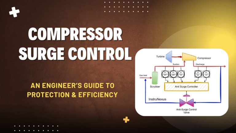
The foundation of a robust ASC system begins with a thorough review of the Piping & Instrumentation Diagram (P&ID). The engineer must be able to trace and critically evaluate the entire anti-surge loop, which typically includes :
-
The compressor and its associated suction and discharge lines.
-
The anti-surge recycle line, which should tap off the main discharge line after the discharge cooler and return to the suction line before the suction scrubber or knock-out drum. This ensures the recycled gas is cooled and any condensed liquids are removed before re-entering the compressor.
-
The anti-surge valve (ASV), designated on the P&ID with a unique tag number.
-
All associated instrumentation, including the flow element (FE), pressure transmitters (PT), and temperature transmitters (TT) at the compressor’s suction and discharge.
During P&ID review, the engineer must verify the correct placement of these components. The flow element, for example, must be located on the compressor’s suction line to accurately measure the total flow entering the machine, including the recycled flow. The pressure and temperature transmitters should be placed to provide representative measurements of the conditions at the compressor flanges. The physical location of the ASV should be as close to the compressor as practical to minimize the transport delay (lag) in the recycle loop, which is critical for fast response.
6.2. Instrumentation Selection: The Criticality of Speed and Accuracy
The performance of the entire ASC loop is fundamentally limited by the quality and speed of its input measurements. The adage “a controller is only as good as its measurements” is especially true for this high-speed application. The system’s ability to react within the tight timeframes required, such as the sub-500 millisecond response time for surge detection cited by API 670, begins with the sensors.
-
Pressure and Flow Transmitters: These are the most critical measurements. The engineer must specify modern electronic transmitters with exceptionally fast response times. Time constants should be in the range of 250 milliseconds or less. Older, slower pneumatic transmitters are entirely unsuitable for this service. The transmitters must also be ranged correctly to provide high-resolution data across the full operating envelope of the compressor.
-
Temperature Sensors: Fast-responding temperature elements (thermocouples or RTDs) are also essential, as temperature is a key input for the invariant coordinate calculations that ensure the accuracy of the surge line model.
-
Fault Tolerance and Redundancy: For critical applications, the design should incorporate redundant transmitters for key measurements. The ASC system must have robust logic to detect a transmitter failure (e.g., through signal validation or deviation checking between redundant sensors) and automatically switch to a safe, conservative control mode or use the healthy sensor to prevent a false trip or a missed protection event.
6.3. Final Control Element Deep Dive: Sizing, Specifying, and Accessorizing the Anti-Surge Valve
The anti-surge valve is arguably the most critical hardware component in the loop. It is not a standard process control valve; it is a specialized piece of safety equipment that must be capable of both precise throttling and extremely rapid emergency action.
-
Speed of Response: This is the paramount design criterion. The valve and actuator assembly must be capable of stroking fully open in approximately 1 to 2 seconds, even for large valve sizes. This is typically achieved by using high-performance, double-acting piston actuators rather than slower diaphragm actuators. To achieve this speed, the actuator is equipped with pneumatic accessories called
volume boosters or relays. These devices act as pneumatic amplifiers, taking the small-volume signal from the controller’s I/P converter and using it to pilot a large, high-capacity air supply directly to the actuator, enabling very fast stroking speeds.
-
Sizing: Correctly sizing the ASV is a critical engineering task. An undersized valve will not be able to pass enough recycle flow to prevent surge under all conditions. An oversized valve will be difficult to control precisely when it is only slightly open (near its seat), leading to instability. A common engineering guideline is to size the valve to have a maximum capacity (Cv) that can handle approximately 1.8 to 2.2 times the flow required to prevent surge under the worst-case operating scenario.
-
Valve Characteristics: A linear flow characteristic is often preferred as it provides a consistent process gain, which simplifies controller tuning. However, some applications may use equal-percentage or quick-opening trims. Advanced digital valve controllers, such as the Emerson FIELDVUE, include characterization functions that can linearize the response of any inherent valve characteristic, providing flexibility.
-
Fail-Safe Design: The valve assembly must be specified to fail-open. This means that on loss of the pneumatic air supply or the electronic control signal, the valve will automatically spring to the fully open position, ensuring that the compressor is protected during a plant upset or power failure.
-
Noise and Vibration Abatement: The throttling of high-pressure gas across the ASV can generate extreme levels of noise and destructive pipe vibration. It is essential to specify the valve with a specialized low-noise trim. These trims use multi-stage, multi-path designs to break the single large pressure drop into many smaller, less energetic pressure drops, which can reduce noise levels by as much as 40 dBA and mitigate damaging vibration.
6.4. Control Loop Tuning and Commissioning Best Practices
Tuning an anti-surge control loop is a high-stakes activity that requires a careful, methodical approach. The objective is to find tuning parameters that make the loop’s response fast and aggressive enough to prevent surge, yet stable enough to avoid control oscillations that could upset the process or cause a spurious trip.
-
Pre-Commissioning Checks: Before any live tuning, all system components must be thoroughly verified. This includes confirming correct installation and calibration of all instruments and performing standalone stroke tests of the ASV to measure its actual opening and closing times and to check for mechanical issues like stiction (static friction) or hysteresis.
-
Tuning Procedure: The compressor is typically placed on full recycle with the ASC controller in manual mode. The engineer then performs a series of small, controlled step changes to the ASV position and records the dynamic response of the process variables (flow and pressures). The data from these step tests are then used to calculate initial PI tuning parameters. The tuning should be asymmetrical, with a higher gain for the valve opening action to ensure a rapid response to an approaching surge, and a lower gain for the closing action to provide a smooth return to normal operation. Digital valve controllers with built-in auto-tuning and performance diagnostic tools can significantly simplify and accelerate this process.
-
System Testing: Once tuned, the entire system should be tested under various operating conditions to ensure it responds correctly to simulated or actual process disturbances.
6.5. Common Troubleshooting Scenarios and Diagnostic Approaches
Even well-designed systems can encounter problems. The I&C engineer must be equipped to diagnose and resolve common issues:
-
Symptom: Unnecessary Recycling (ASV opens when the compressor appears stable).
-
Potential Causes:
-
Incorrect Surge Line: The SLL programmed into the controller may not accurately represent the compressor’s true performance. This can be due to outdated manufacturer data or a shift in performance caused by mechanical wear or fouling.
-
Faulty Instrumentation: A drifting pressure or flow transmitter can provide an erroneous calculation of the operating point, tricking the controller into thinking it is closer to surge than it actually is.
-
Environmental Factors: In some cases, the electronic components of the controller itself can be sensitive to ambient temperature changes in the control room or rack room, causing its output to drift.
-
-
Symptom: The compressor surges despite the ASC system being active.
-
Potential Causes:
-
Slow Valve Response: The ASV is not opening fast enough. This could be due to a mechanical problem with the valve or actuator, a failing positioner, or an undersized air supply or volume booster.
-
Sluggish Controller Tuning: The controller’s proportional gain may be set too low, resulting in a response that is too slow to keep up with a fast-moving transient.
-
Insufficient Surge Margin: The SCL may be set too close to the SLL, leaving insufficient time for the control loop to react before the operating point crosses into the unstable region.
Modern ASC systems provide powerful tools for diagnostics. The high-speed event logs and trend data from the controller are invaluable for performing a root cause analysis after a trip. Furthermore, the advanced diagnostics available from digital valve controllers can proactively report on the health of the ASV, detecting issues like increased friction or air leaks before they lead to a failure of the protection system.
Conclusion
The protection of critical centrifugal and axial compressors from the destructive forces of surge is a non-negotiable requirement for safe and reliable plant operation. The anti-surge control system stands as the primary defense, an intricate fusion of aerodynamic principles, high-speed instrumentation, specialized mechanical hardware, and sophisticated control algorithms.
The analysis reveals that compressor surge is a system-level phenomenon, where the dynamic interaction between the compressor and its associated process piping and volumes dictates the nature and severity of the instability. Consequently, effective control demands a holistic approach that considers the entire compression loop, not just the turbomachine in isolation.
The evolution of ASC technology has been driven by a dual mandate: to provide uncompromising safety while maximizing operational efficiency. This has led to a clear progression from simple feedback control to advanced, multi-layered strategies. Modern systems employ invariant coordinate calculations to adapt to changing gas conditions, predictive algorithms that anticipate surge by analyzing the operating point’s velocity, and hybrid architectures that combine precise closed-loop modulation with aggressive open-loop responses for handling severe transients.
The industrial landscape offers a choice between two primary architectural philosophies. Specialized providers deliver dedicated, purpose-built controllers that represent the pinnacle of focused performance, while major DCS vendors advocate for integrating this critical function into a unified plant-wide control platform, prioritizing streamlined maintenance and data accessibility. The selection between these approaches constitutes a significant strategic decision with long-term operational implications.
For complex multi-compressor networks, advanced load-sharing control is essential. By moving beyond simple load-splitting and adopting the principle of maintaining an “equidistant from surge” margin across all units, these systems create a coordinated network that is more stable, efficient, and robust than the sum of its individual parts.
Ultimately, the integrity of the entire anti-surge protection system rests on the expertise of the instrumentation engineer. This role requires a deep, integrated understanding of the complete control loop—from the dynamic response of sensors and transmitters to the intricate tuning of the control algorithm and the critical performance of the high-speed anti-surge valve. The engineer must act as the guardian of the system’s dynamic response, ensuring that every component in the chain is specified and maintained to meet the millisecond-level demands of this vital protective function. Through diligent design, commissioning, and maintenance, these systems ensure that critical turbomachinery assets can continue to operate safely and efficiently at the heart of the modern industrial landscape.