
Mastering Process Control: Unveiling the Power of Cascade Control Loops
In the intricate dance of industrial process control, stability, accuracy, and efficiency are paramount. Engineers constantly seek ways to optimize system performance, minimize disturbances, and ensure product quality. While a simple single-loop PID controller can handle many tasks, some processes present challenges that demand a more sophisticated approach. This is where the elegance and power of cascade control loops truly shine.
If you’ve ever struggled with processes exhibiting significant dead time, high-frequency disturbances, or sluggish responses, then understanding and implementing cascade control could be your game-changer. This blog post will dive deep into what cascade control is, why it’s so effective, and how to apply it with practical examples and clear illustrations.
What is Cascade Control? The Core Concept
At its heart, cascade control involves two (or more) controllers working together, where the output of the “primary” (or outer) controller sets the setpoint for the “secondary” (or inner) controller. Think of it as a supervisor (primary) giving instructions to a worker (secondary), and the worker then directly manipulates the final control element.
The primary controller is typically responsible for controlling the most critical process variable – let’s call it the master PV. The secondary controller, on the other hand, is responsible for controlling an intermediate process variable – the slave PV – which directly affects the master PV and can be controlled more rapidly.
Key Components of a Cascade Loop:
Primary (Master) Controller:
Input: Master Process Variable (PV)
Setpoint: Master Setpoint (SP) – the desired value for the main process
Output: Slave Controller Setpoint (SP) – dictates the desired value for the inner loop
Secondary (Slave) Controller:
Input: Slave Process Variable (PV) – a variable that can be controlled quickly
Setpoint: Received from the Primary Controller’s output
Output: Manipulates the Final Control Element (e.g., valve, heater, pump speed)
Let’s visualize this fundamental structure:
In Figure 1, notice how the primary controller doesn’t directly touch the valve. Instead, it adjusts the setpoint of the secondary controller, which then takes care of the immediate action.
Why Use Cascade Control? The Advantages
Cascade control isn’t just a fancy way of adding more controllers; it offers significant performance benefits in specific scenarios:
Rejection of Inner Loop Disturbances: This is arguably the most significant advantage. The secondary controller can quickly detect and compensate for disturbances occurring within its own loop before they can propagate and affect the primary process variable. This leads to much smoother and more stable control of the master PV.
Improved Response to Setpoint Changes: Because the inner loop is typically faster, it can respond more rapidly to changes in the primary controller’s output (its setpoint). This results in a quicker and more precise response of the overall system to master setpoint changes.
Handling Non-Linearities: The inner loop can often linearize the response of the final control element. For example, a flow control loop might compensate for non-linear valve characteristics, presenting a more linear response to the primary controller.
Better Control of Slow Processes with Fast Dynamics: Processes with large time constants (slow response) but also fast-acting disturbances can benefit greatly. The inner loop handles the rapid disturbances, allowing the outer loop to focus on the overall, slower control.
Easier Tuning: Tuning two smaller loops is often simpler and more robust than tuning a single, complex loop that has to deal with both fast and slow dynamics, and multiple disturbance types. You tune the inner loop first, making it as fast and stable as possible, then tune the outer loop.
When is Cascade Control Most Effective?
Cascade control is particularly effective in situations where:
There is a measurable secondary variable that directly influences the primary variable.
The secondary loop’s dynamics are significantly faster than the primary loop’s dynamics (typically 5-10 times faster). If the inner loop is too slow, the benefits are diminished.
Disturbances frequently occur within the inner loop, which would otherwise take a long time to be corrected by a single-loop controller acting on the primary variable.
Non-linearities exist in the final control element or the immediate process that the inner loop can mitigate.
Practical Examples of Cascade Control Loops
Let’s explore some common industrial applications to solidify your understanding.
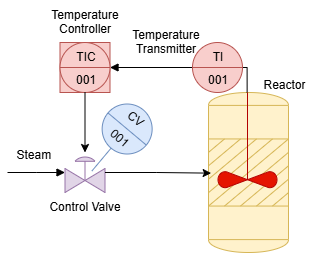
Example 1: Temperature Control of a Stirred Tank Reactor with Jacketed Heating
This is a classic and very illustrative example. Imagine you want to precisely control the temperature inside a chemical reactor. The reactor itself has a large thermal mass, making its temperature a slow-responding variable. Heat is supplied via a steam jacket. The primary disturbance is often fluctuating steam pressure, which directly affects the heat transfer.
Single Loop Approach:
A single PID controller would measure the reactor temperature and directly manipulate the steam valve. If the steam pressure drops, the reactor temperature would begin to fall slowly. The controller would eventually detect this, open the valve further, and the temperature would slowly recover. This response would be sluggish.
Cascade Control Approach:
Here, we introduce a secondary flow control loop.
Primary (Master) Controller:
PV: Reactor Temperature
SP: Desired Reactor Temperature
Output: Desired Steam Flow Rate (this becomes the setpoint for the secondary controller)
Secondary (Slave) Controller:
PV: Actual Steam Flow Rate (measured by a flow transmitter)
SP: Desired Steam Flow Rate (from the primary controller)
Output: Manipulates the Steam Control Valve
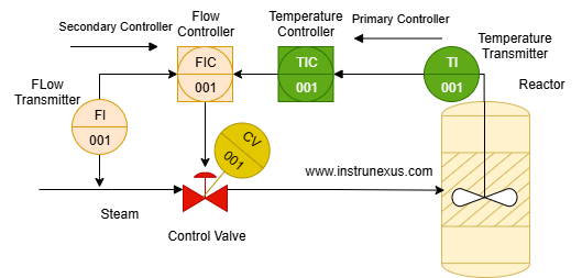
How it works:
If the steam pressure fluctuates, the secondary flow controller immediately detects a deviation from its setpoint (the desired steam flow rate) and adjusts the steam valve to maintain that flow. This disturbance is caught and corrected by the fast inner loop before it significantly impacts the reactor temperature. The primary controller sees a much more stable heat input, leading to a much more stable reactor temperature.
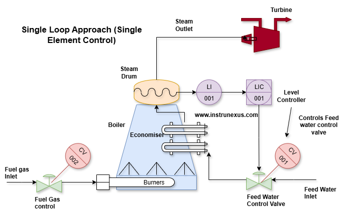
Example 2: Boiler Drum Level Control
Maintaining a stable water level in a boiler drum is critical for safety and efficiency. Too low, and the boiler tubes can overheat; too high, and steam quality suffers, potentially damaging downstream equipment. Fluctuations in steam demand (load) and feedwater pressure are common disturbances.
Single Loop Approach (Single Element Control):
A single controller measures drum level and manipulates the feedwater valve. This works okay for slow changes but can struggle with rapid load swings, especially due to a phenomenon called “swell and shrink.” When steam demand increases, pressure drops, and the water level appears to rise (swell) due to increased bubbling, even though the mass of water is decreasing. A single controller might incorrectly reduce feedwater.
The diagram you provided (Figure 5) is actually a “three-element” control scheme, which is a common and highly effective advanced control strategy for boiler drum level. While it incorporates a cascade element, it also uses feedforward control, which is a step beyond a basic two-element cascade. Let’s adjust the explanation to accurately reflect a two-element cascade for drum level control first, and then touch on the three-element as an advanced point.
Example 2 (Revised): Boiler Drum Level Control (Two-Element Cascade)
For a more robust drum level control, especially against feedwater pressure fluctuations, a two-element cascade can be implemented.
Primary (Master) Controller:
PV: Boiler Drum Level
SP: Desired Drum Level
Output: Desired Feedwater Flow Rate (this becomes the setpoint for the secondary controller)
Secondary (Slave) Controller:
PV: Actual Feedwater Flow Rate
SP: Desired Feedwater Flow Rate (from the primary controller)
Output: Manipulates the Feedwater Control Valve
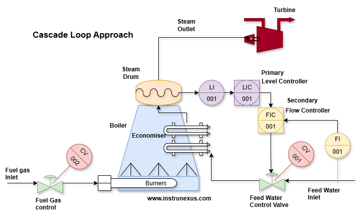
How it works:**
If the feedwater supply pressure fluctuates, the secondary flow controller immediately adjusts the feedwater valve to maintain the exact flow rate requested by the primary level controller. This means the primary level controller sees a consistent flow of water for any given output, making its job easier and the overall drum level control more stable. This setup handles feedwater supply disturbances much better than a single loop.
Advanced Drum Level Control: Three-Element Cascade (with Feedforward)
The diagram you initially provided actually depicts a three-element control system, which builds upon the cascade concept by adding a feedforward element.
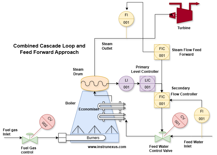
In Figure 6 (Three-Element Control), the steam flow rate (steam demand) is measured and used as a “feedforward” signal. This signal directly adjusts the setpoint of the feedwater flow controller in anticipation of the change in drum level that increasing or decreasing steam demand would cause. This proactive action, combined with the cascade structure for feedwater flow control, provides exceptionally stable drum level.
While strictly speaking, the three-element is a form of cascade, it’s a more sophisticated example that also incorporates feedforward, demonstrating how cascade can be integrated into even more complex control strategies.
Example 3: Compressor Surge Control
Compressors have a “surge limit” – a minimum flow rate below which the compressor becomes unstable, leading to rapid flow reversals, vibrations, and potential damage. It’s critical to keep the compressor operating above this limit. The anti-surge valve allows some gas to bypass the compressor or recycle back to the suction to maintain flow.
Cascade Control Approach:
Primary (Master) Controller:
PV: Compressor operating point relative to the surge line (often calculated from flow and differential pressure).
SP: A setpoint slightly above the surge line.
Output: Desired Anti-Surge Valve Position (or a desired recycle flow)
Secondary (Slave) Controller:
PV: Actual Anti-Surge Valve Position (measured by a position transmitter) or actual recycle flow.
SP: Desired Valve Position/Recycle Flow (from the primary controller)
Output: Manipulates the Anti-Surge Valve Actuator
How it works:**
The inner loop ensures that the anti-surge valve precisely achieves the position commanded by the primary surge controller, regardless of friction, sticky valve packing, or varying air supply pressure to the actuator. This fast, accurate positioning of the valve is crucial for preventing the compressor from entering surge, as the surge event can happen extremely quickly. The primary controller, therefore, has a reliable way to manipulate the flow to protect the compressor.
Implementing and Tuning Cascade Control Loops
Implementing cascade control requires careful consideration of both hardware and software.
Hardware/Instrumentation:
Sensors: You need reliable measurements for both the primary and secondary process variables.
Transmitters: To convert sensor signals into control system inputs.
Final Control Element: A valve, pump, heater, etc., that the secondary controller directly manipulates.
Controllers: Your DCS (Distributed Control System), PLC (Programmable Logic Controller), or standalone PID controllers must support cascade functionality.
Software/Configuration:
Controller Modes: Both controllers usually operate in automatic mode, but the secondary controller must be able to switch between local (manual or single-loop automatic) and cascade mode. When the primary controller is in manual, the secondary controller should typically revert to manual or be held at a fixed setpoint.
Interlocks & Safeties: Consider what happens if a sensor fails or a controller is put in manual. Proper interlocks are essential to prevent dangerous or unstable conditions.
Tuning Procedure:
Tuning a cascade loop follows a specific, logical sequence:
Tune the Secondary (Inner) Loop First:
Put the primary controller in manual mode. This allows you to directly manipulate the setpoint of the secondary controller.
Treat the secondary loop as a standalone single loop. Tune it to be as fast and stable as possible, ensuring it responds well to setpoint changes and rejects disturbances effectively. Common methods like Ziegler-Nichols or trial-and-error can be used.
Once tuned, verify its performance.
Tune the Primary (Outer) Loop Second:
Switch the secondary controller into cascade mode (where its setpoint is taken from the primary controller’s output).
Now, put the primary controller into automatic mode.
Treat the entire inner loop (secondary controller + process) as a single, faster final control element for the primary controller.
Tune the primary controller using standard tuning methods, aiming for good regulation of the master PV and smooth response to master setpoint changes. The primary controller will typically have slower, more conservative tuning parameters compared to the secondary controller.
Potential Pitfalls and Considerations
While powerful, cascade control isn’t a silver bullet. Be aware of these potential issues:
Sensor Failure: If the secondary PV sensor fails, the secondary loop will become unstable, and the primary loop will also lose control. Robust fault detection and fail-safe strategies are crucial.
Inner Loop Instability: If the inner loop is poorly tuned or becomes unstable, it will directly destabilize the outer loop and the entire process.
Slow Inner Loop: If the inner loop is not significantly faster than the outer loop, the benefits of cascade control are greatly reduced, and a single loop might perform just as well.
Limited Operating Range: Ensure the inner loop can handle the full range of setpoints that the primary controller might demand.
Switching Modes: Seamless and safe bumpless transfer between manual, automatic, and cascade modes is essential.
Conclusion: Elevating Your Process Control Strategy
Cascade control loops represent a fundamental yet highly effective advanced control strategy. By breaking down a complex control problem into two interconnected, manageable loops, they offer superior disturbance rejection, faster response times, and enhanced stability compared to single-loop control.
From precisely maintaining reactor temperatures against steam pressure fluctuations to safeguarding critical rotating equipment like compressors, the applications of cascade control are widespread across various industries. Understanding its principles, knowing when to apply it, and mastering its tuning are invaluable skills for any process engineer or technician aiming to optimize industrial processes.
By strategically implementing cascade control, you can move beyond basic regulation, achieving tighter control, reducing variability, and ultimately driving greater efficiency and safety in your operations. So, the next time you encounter a challenging process, ask yourself: Is there a faster, measurable intermediate variable I can control? If so, cascade control might just be the elegant solution you’ve been looking for.
One Response