
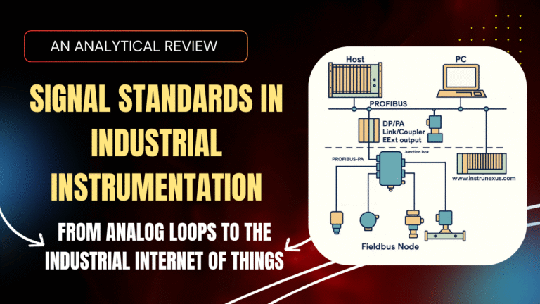
An Analytical Review of Signal Standards in Industrial Instrumentation: From Analog Loops to the Industrial Internet of Things
Abstract: This report provides a comprehensive examination of the principal signal standards employed in modern industrial instrumentation. It traces the technological evolution from the foundational 4-20 mA analog current loop to the hybrid HART protocol, the fully digital Fieldbus architectures (FOUNDATION Fieldbus and PROFIBUS), and the emergence of wireless standards (WirelessHART and ISA100.11a). Each standard is analyzed in terms of its operational principles, physical layer characteristics, data communication capabilities, advantages, and limitations. A comparative framework is established to evaluate these protocols across critical performance metrics, including data integrity, determinism, diagnostic capabilities, and installation complexity. The report culminates in a discussion of the ongoing convergence with Industrial Ethernet and the future trajectory of industrial communication in the era of Industry 4.0 and the IIoT.
Part 1: The Foundation of Industrial Signaling – The 4-20 mA Current Loop
The 4-20 mA current loop stands as the most enduring and widely implemented analog signaling standard in the history of industrial automation. Its elegant simplicity, inherent robustness, and cost-effectiveness established it as the bedrock upon which modern process control was built. Understanding its operational principles is not merely a historical exercise; it is fundamental to appreciating the design philosophies, compromises, and evolutionary steps that define the more advanced digital protocols that followed. The standard’s influence is so profound that its core concepts shaped the development of subsequent technologies, which were often designed to augment or coexist with the massive installed base of 4-20 mA infrastructure.
1.1. Historical Context: From Pneumatics to Electronics
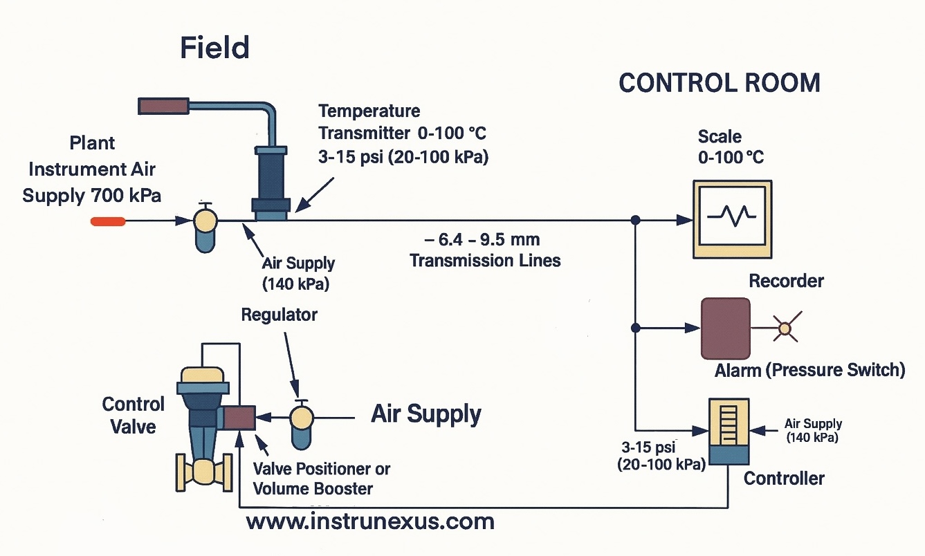
Before the advent of cost-effective electronics, industrial process control was a mechanical and pneumatic endeavor. In the early to mid-20th century, compressed air was the primary medium for transmitting process information and actuating control elements. The 3-15 pounds per square inch (psi) pneumatic signal became the prevailing standard. This system was robust and intrinsically safe for hazardous environments, but it was also energy-intensive, requiring large compressors, and involved cumbersome and leak-prone tubing installations.
The commercialization of the transistor in the 1950s catalyzed a shift toward electronic control systems. Electronics offered greater accuracy, lower energy requirements, and easier installation and maintenance compared to pneumatic systems. In this transition, early electronic signals varied, but the industry soon coalesced around the 4-20 mA current loop, which was formally standardized in the 1970s as ANSI/ISA S50.
The design of the 4-20 mA standard was not arbitrary; it was a direct electronic emulation of the preceding 3-15 psi pneumatic standard. The pneumatic system’s use of 3 psi as its zero point was a critical feature. Pressures below this level were difficult to measure reliably, and a reading of 0 psi clearly indicated a system failure, such as a broken air line. The designers of the 4-20 mA standard deliberately inherited this crucial fault-detection capability. A signal of 0 mA would be ambiguous—it could represent a true zero process value or a broken wire. By offsetting the zero point to 4 mA, the system created an unambiguous fault condition (a 0 mA reading), directly translating the reliability principle of the pneumatic era into an electronic format.
1.2. Principle of Operation: A Deep Dive into the Current Loop
The 4-20 mA current loop is a series electrical circuit designed to transmit a single process variable from a field instrument to a control system. Its operation is governed by fundamental principles of electricity, primarily Ohm’s Law and Kirchhoff’s Laws.
Core Components
A standard two-wire current loop consists of four essential components connected in series:
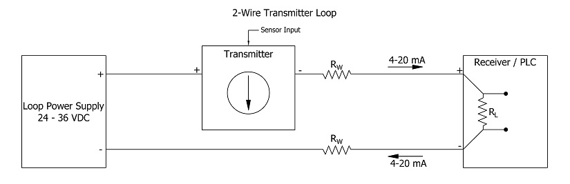
- DC Power Supply: Provides the energy to drive the current through the loop. A 24V DC supply is the most common industry standard.
- Transmitter: The “smart” component of the loop. It measures a physical process variable (e.g., temperature, pressure, flow, level) and regulates the current flowing through the circuit to a value between 4 mA and 20 mA that is directly proportional to the measurement. For example, in a pressure transmitter ranged for 0 to 100 bar, 0 bar would correspond to a 4 mA current, 100 bar to 20 mA, and 50 bar to 12 mA.
- Receiver/Controller: This is typically an input module on a Programmable Logic Controller (PLC) or Distributed Control System (DCS). It measures the current in the loop to determine the value of the process variable.
- Wiring: The physical conductors (typically a twisted pair of copper wires) that connect all components in a series circuit.
Fundamental Physics
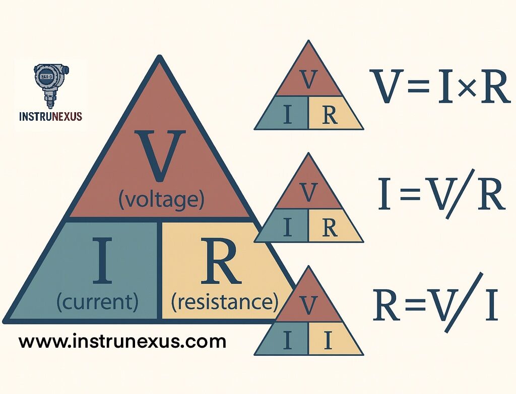
The transmitter controls the loop current by dynamically adjusting its internal electrical resistance. According to Ohm’s Law, which states that voltage (V) equals current (I) multiplied by resistance (R), or I=V/R, for a fixed supply voltage, the current in the loop is inversely proportional to the total loop resistance. The transmitter effectively acts as a variable resistor, modulating the total loop resistance to maintain the current at the desired level, irrespective of variations in wire resistance or the load from the receiver.
The most critical principle underpinning the accuracy of the 4-20 mA loop is Kirchhoff’s Current Law, which states that the current is the same at every point in a simple series circuit. This means that the current value set by the transmitter is the same value measured by the receiver, regardless of the distance between them (within the system’s power limits). This physical law is the reason for the standard’s exceptional immunity to signal degradation over long distances.
The receiver measures the current by passing it through a high-precision sense resistor, often 250 Ω. This converts the 4-20 mA current signal into a proportional 1-5 V DC voltage signal (V=0.004A×250Ω=1V; V=0.020A×250Ω=5V), which is easily read by the analog-to-digital converter of the control system’s input card.
1.3. The “Live Zero” Concept: More Than Just a Starting Point
The choice of 4 mA as the lower limit of the signal range is one of the standard’s most important design features, known as the “live zero”. This concept provides two distinct and critical benefits.
Primary Benefit – Fault Detection
The live zero allows the control system to distinguish between a valid zero-percent process reading and a system fault. The signal ranges are interpreted as follows:
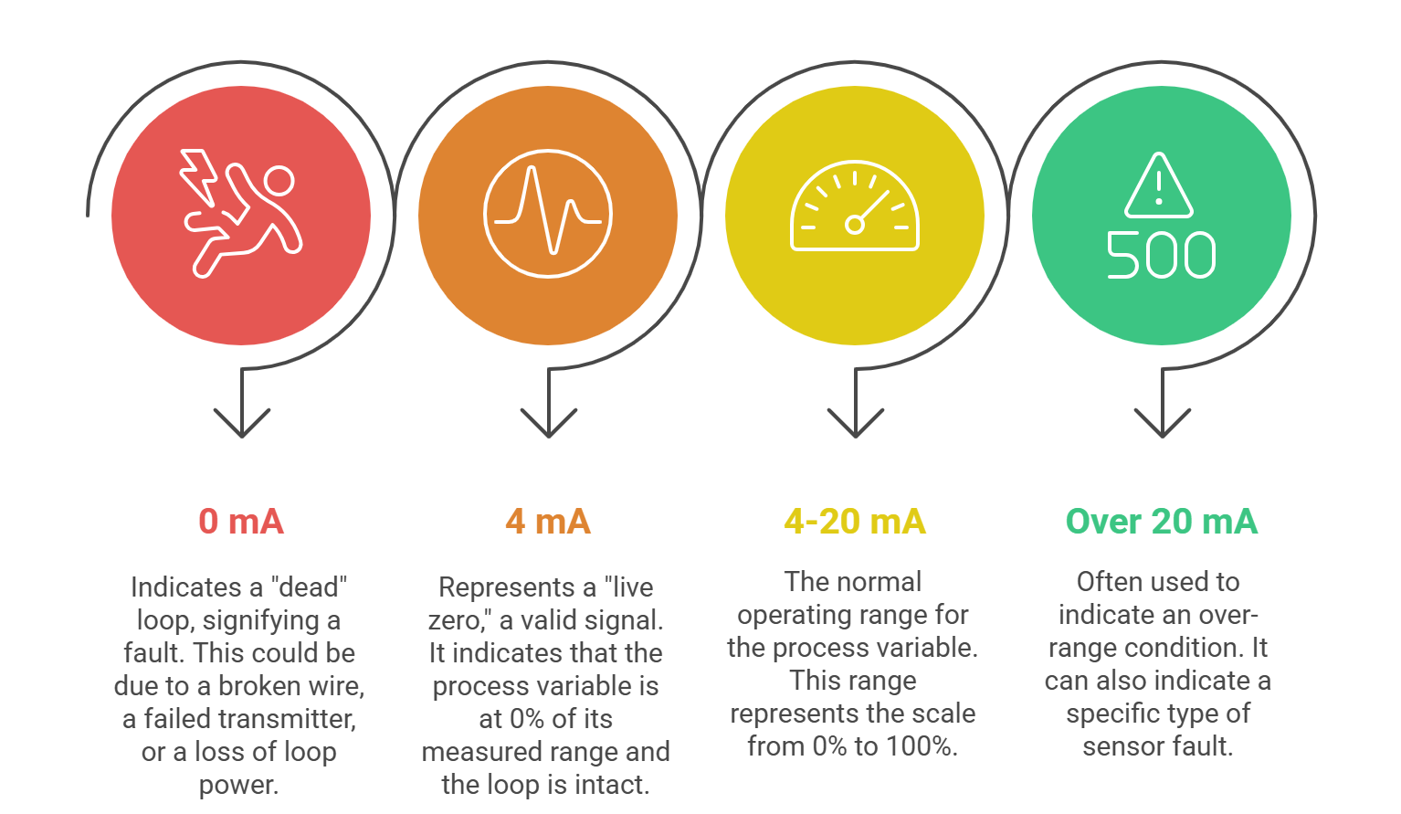
- 0 mA: Indicates a “dead” loop, signifying a fault such as a broken wire, a failed transmitter, or a loss of loop power.
- 4 mA: Represents a “live zero,” a valid signal indicating that the process variable is at 0% of its measured range (e.g., 0 bar pressure, 0°C temperature) and that the loop is intact and functioning correctly.
- 4-20 mA: The normal operating range for the process variable, from 0% to 100%.
- > 20 mA: Often used to indicate an over-range condition or a specific type of sensor fault (e.g., >21 mA).
This clear distinction between a valid zero and a fault condition is a cornerstone of the standard’s reliability in industrial environments.
Secondary Benefit – Loop Power
The minimum current of 4 mA provides a sufficient “headroom” of power for the transmitter’s electronics to operate. This enables the use of “two-wire” or “loop-powered” transmitters, which draw their operating power directly from the same two wires that carry the signal. This design elegantly eliminates the need for a separate power supply and associated wiring for each field device, significantly simplifying installation and reducing overall cost.
1.4. Analysis of Advantages and Disadvantages
The longevity of the 4-20 mA standard is a testament to its well-balanced set of advantages, though it is not without significant limitations.
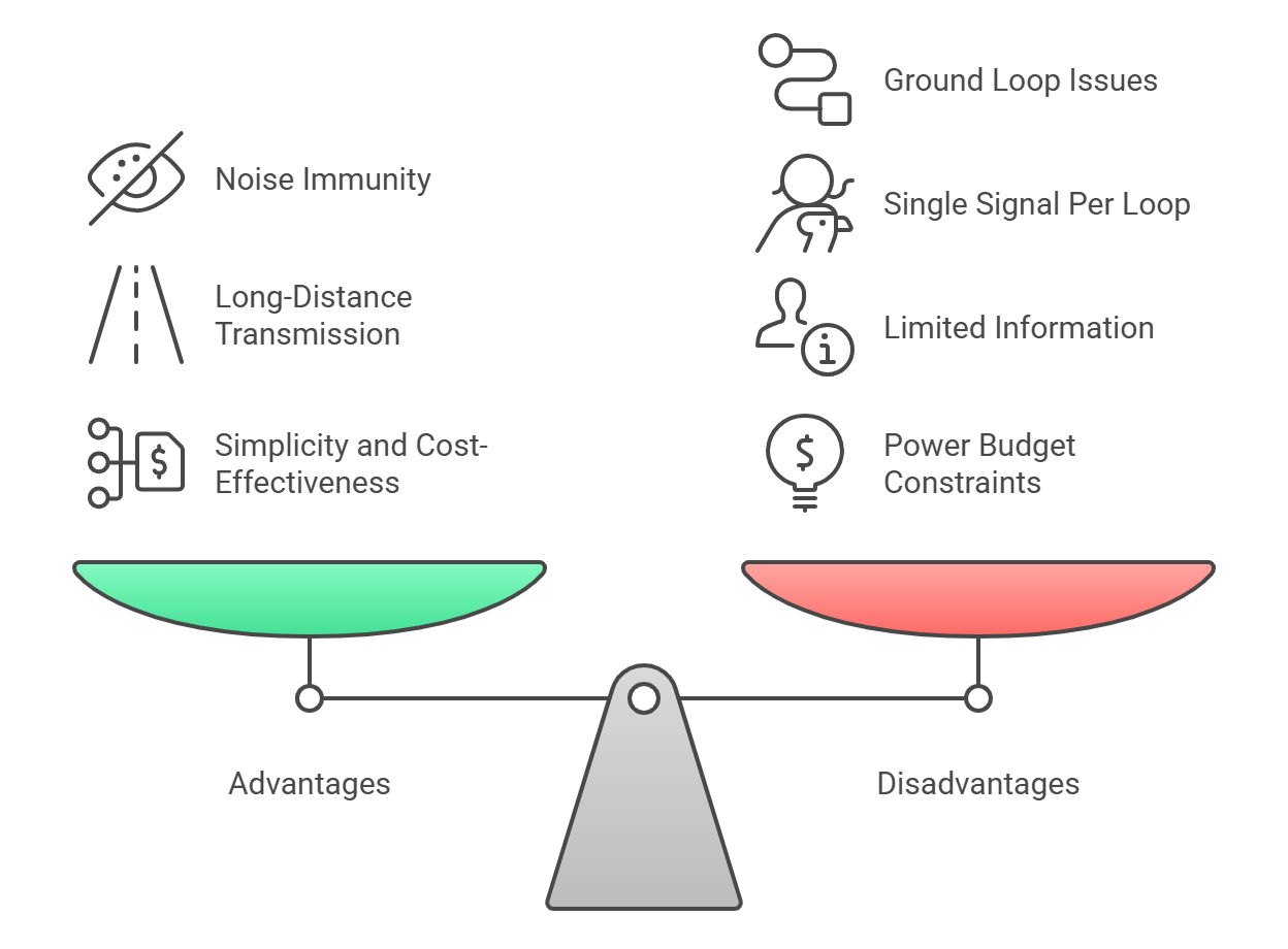
Advantages
- Noise Immunity: In electrically noisy industrial environments filled with motors, drives, and other sources of electromagnetic interference (EMI), current signals are inherently more robust than voltage signals. Current loops are low-impedance circuits, making them less susceptible to induced noise voltages and crosstalk from adjacent cables.
- Long-Distance Transmission: As dictated by Kirchhoff’s Law, the current signal does not degrade or attenuate over long cable runs due to wire resistance, unlike voltage signals which experience voltage drop (Vdrop=I×Rwire). This allows for accurate signal transmission over distances of thousands of feet.
- Simplicity and Cost-Effectiveness: The standard is conceptually simple, easy to install, and can be diagnosed and troubleshot with basic, inexpensive tools like a digital multimeter. The use of two-wire loop-powered devices further reduces wiring and installation costs.
Disadvantages
- Single Signal Per Loop: Each current loop can only transmit a single analog process variable. In a modern plant with thousands of measurement points, this point-to-point architecture requires extensive and costly wiring, marshalling cabinets, and I/O cards.
- Ground Loop Issues: While robust, current loops are not immune to all electrical issues. If a loop is grounded at more than one point, differences in ground potential can create a “ground loop,” allowing stray currents to flow that can introduce noise and inaccuracies into the measurement. Proper isolation is required to prevent this, which can add complexity.
- Limited Information: The loop’s sole function is to communicate the value of the primary process variable. It has no capacity to transmit additional information, such as device status, diagnostic alerts, configuration parameters, or secondary process variables. This limitation was a primary driver for the development of smarter protocols.
- Power Budget Constraints: The total resistance in the loop (from the wiring and all receiver loads) plus the voltage required by the transmitter must not cause a total voltage drop that exceeds the power supply’s voltage. This “loop budget” or “compliance voltage” limit means that there is a maximum number of devices and a maximum cable length that a given loop can support before the transmitter is unable to drive the full 20 mA signal.
The immense success and simplicity of the 4-20 mA loop led to a massive global installed base, creating a powerful technological inertia. This widespread adoption became the single most significant factor driving the development of “hybrid” protocols like HART. These newer protocols were designed to enhance, rather than replace, the existing infrastructure. A fully digital, disruptive technology like Fieldbus, which could not leverage this vast pre-existing wiring and knowledge base, consequently faced a much steeper adoption curve. The success of 4-20 mA did not just solve the problem of reliable analog signaling; it created a new challenge for future technologies—the challenge of backward compatibility.
Part 2: The Hybrid Solution – Highway Addressable Remote Transducer (HART) Protocol
As instrumentation became more sophisticated with the integration of microprocessors, the limitations of the purely analog 4-20 mA signal became increasingly apparent. There was a growing need to access the rich diagnostic and configuration data locked inside these “smart” devices without requiring a technician to physically visit each instrument. The Highway Addressable Remote Transducer (HART) protocol emerged as the critical “bridge” technology, ingeniously adding digital communication capabilities onto the existing analog infrastructure, thereby unlocking the potential of smart instrumentation while minimizing disruption and cost.
2.1. Genesis and Design Philosophy
The HART protocol was developed in the mid-1980s by Rosemount Inc. and was subsequently released as an open standard in 1989, with its stewardship transferred to the independent HART Communication Foundation (now part of FieldComm Group).
The core objective of HART was explicitly not to replace the 4-20 mA standard but to augment it. Its design philosophy was rooted in a pragmatic engineering compromise that prioritized economic reality and backward compatibility over technological purity. The primary goal was to enable two-way digital communication with smart field devices over the same two wires already used for the 4-20 mA analog signal. This “hybrid” approach allowed plants to gain the benefits of digital data—such as remote configuration, diagnostics, and multi-variable reporting—while preserving their enormous investment in existing wiring, control strategies, and I/O systems.
2.2. Technical Implementation: Superimposing Digital on Analog
HART achieves its hybrid communication by superimposing a low-level, alternating current (AC) digital signal on top of the high-level, direct current (DC) 4-20 mA analog signal.
Frequency Shift Keying (FSK)
The protocol employs the Bell 202 Frequency Shift Keying (FSK) standard, a proven and reliable method used in early telephone modems. The digital data is encoded using two distinct frequencies:
- A frequency of 1200 Hz represents a binary ‘1’.
- A frequency of 2200 Hz represents a binary ‘0’.
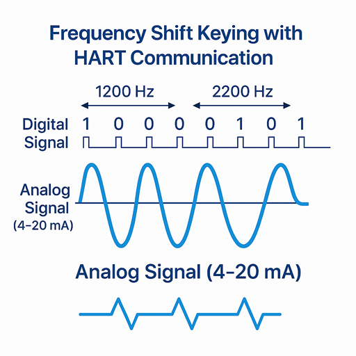
This AC sine wave has an amplitude of approximately ±0.5 mA, which is overlaid on the DC current loop. The key to this technique is that the average value of the symmetrical AC sine wave is zero. Consequently, it does not affect the average DC value of the 4-20 mA signal, which represents the primary process variable. The control system’s analog input card, designed to measure the DC current, effectively filters out the high-frequency AC component, ensuring that the primary control signal remains uninterrupted and unaffected.
The choice of the relatively slow 1200 bits per second (bps) Bell 202 standard was a deliberate design decision. A faster, more complex modulation scheme might have required more power or carried a higher risk of interfering with the mission-critical analog control signal. By selecting a proven, simple, and low-energy standard, the designers ensured the digital channel was subservient to the analog one. This was essential for gaining acceptance in conservative process industries where control loop reliability is paramount, reflecting a philosophy of evolutionary, rather than revolutionary, technological adoption.
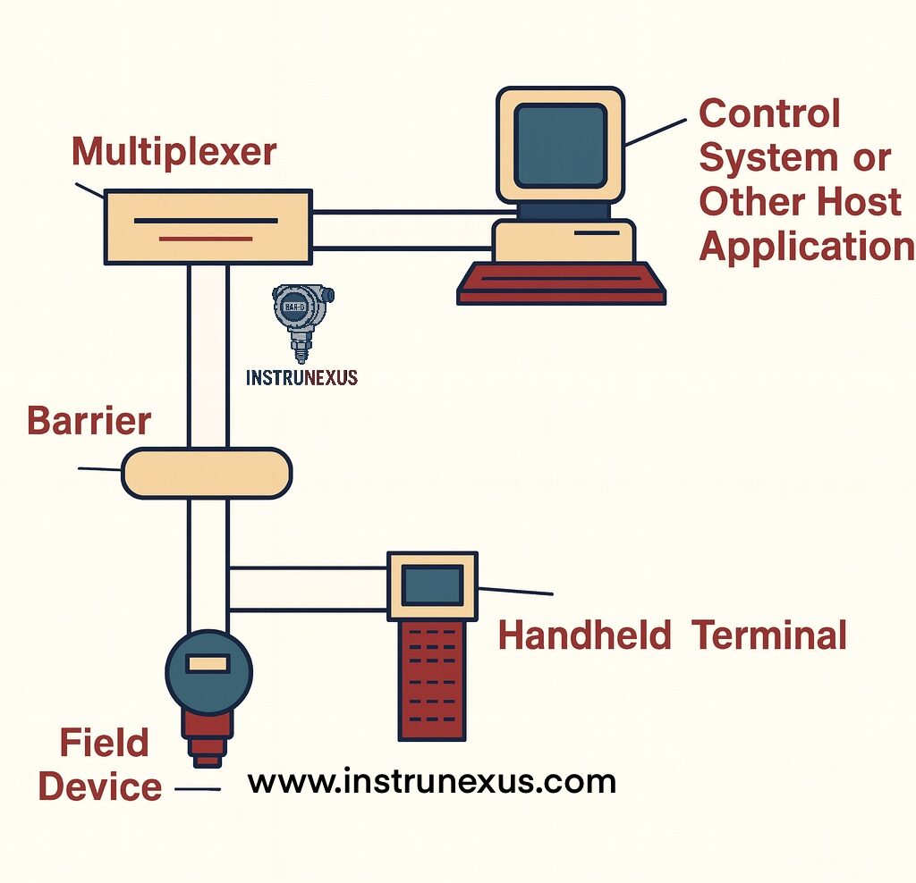
2.3. Operational Modes and Network Architecture
HART is a master-slave protocol, meaning that a slave device (the field instrument) will only transmit digital data when requested by a master device (such as a host system or handheld communicator). The protocol supports up to two masters (a primary, like a DCS, and a secondary, like a handheld tool) which can coexist on the loop.
Point-to-Point Mode
This is the most prevalent operational mode and mirrors the standard 4-20 mA wiring configuration. A single HART instrument is connected to a control system input. In this mode, the two communication channels are used simultaneously:
- Analog Channel: The 4-20 mA signal continuously transmits the primary process variable (PV) for real-time control.
- Digital Channel: The FSK signal is used on-demand to send and receive configuration data, diagnostic information, and additional measured variables.
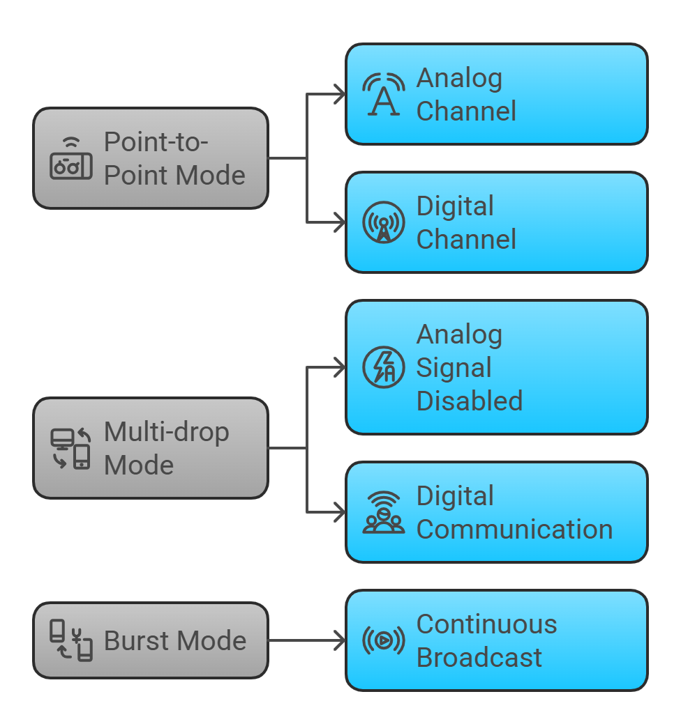
Multi-drop Mode
In this mode, up to 16 HART devices can be connected in parallel on a single twisted-pair cable, functioning as a true digital bus. To enable this, the analog signal is disabled; the loop current is fixed at a minimum value (typically 4 mA) solely to provide power to the devices. All communication of process variables and other data occurs digitally. Each device on the bus must be assigned a unique polling address from 1 to 15 (address 0 is reserved for point-to-point mode). Due to the need to poll each device sequentially, this mode is significantly slower than point-to-point and is generally restricted to monitoring non-critical variables in slow-moving processes.
Burst Mode
Burst mode is an exception to the strict master-slave communication model. A single slave device can be configured to continuously and automatically broadcast a standard HART reply message (typically the PV) three to four times per second, without needing to be prompted by a master’s request. This provides faster updates for a single variable over the digital channel but is limited to one device per loop in this mode.
2.4. Capabilities Unlocked by HART
The introduction of the digital channel fundamentally transformed the capabilities of field instrumentation.
Remote Configuration and Diagnostics
HART’s most significant benefit is the ability for technicians to communicate with a smart instrument remotely. Using a handheld HART communicator or PC-based asset management software connected anywhere on the loop, an operator can:
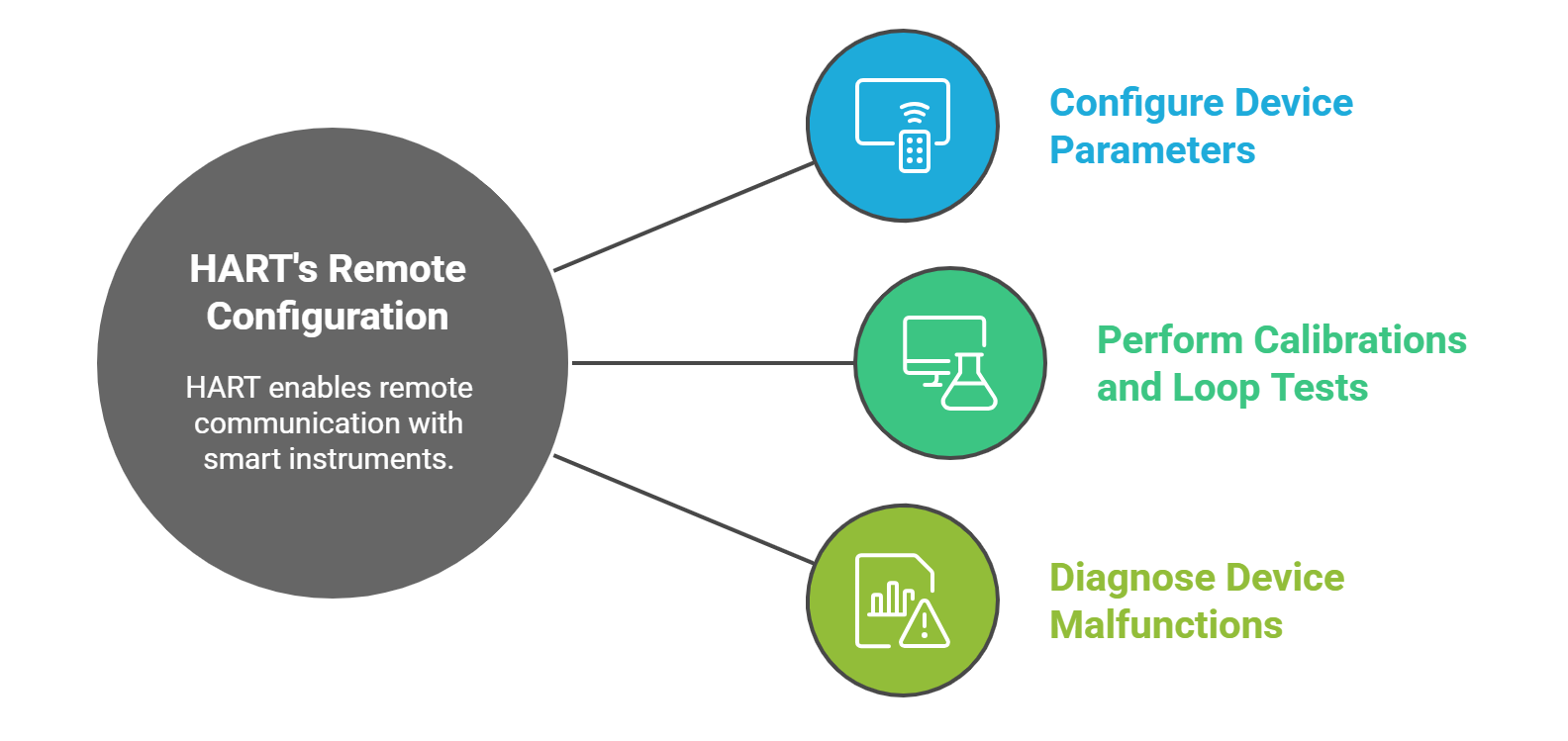
- Configure device parameters (e.g., set ranges, change units).
- Perform calibrations and loop tests.
- Diagnose device malfunctions by reading error codes and status information.
This capability drastically reduces maintenance time, improves safety by minimizing trips to hazardous or hard-to-reach locations, and ensures devices are configured correctly.
Transmission of Additional Variables
![]()
HART allows a single instrument to transmit multiple variables. While the 4-20 mA signal is tied to the Primary Variable (PV), the digital channel can carry a Secondary Variable (SV), Tertiary Variable (TV), and Quaternary Variable (QV). For example, a multivariable mass flow meter can transmit mass flow via the analog signal, while simultaneously providing temperature, pressure, and density readings digitally. A pressure transmitter can report its own internal electronics temperature alongside the process pressure.
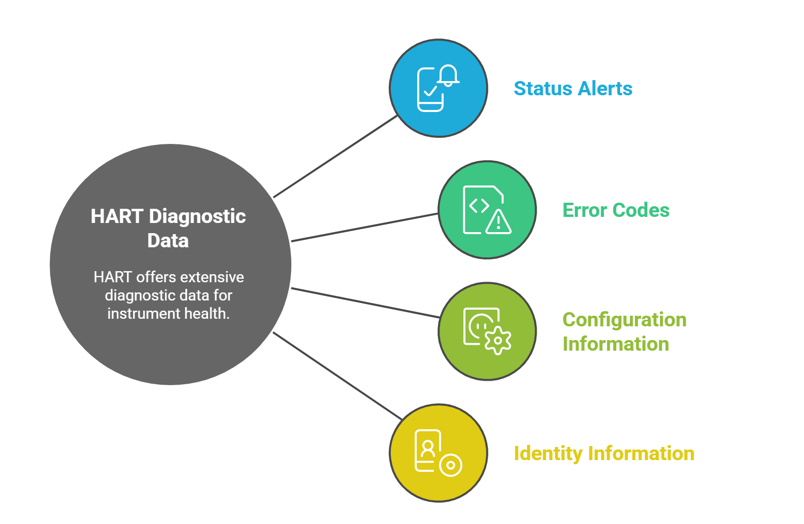
Device Health and Status
Beyond process values, HART provides access to a wealth of diagnostic data about the health of the instrument itself. This includes status alerts, error codes, and information about the device’s configuration and identity. This capability was a foundational step toward modern predictive maintenance strategies.
The introduction of HART effectively bifurcated instrumentation data into two distinct categories: real-time “control” data and non-real-time “information” data. The 4-20 mA signal remained the domain of the control system (DCS/PLC), which consumed it for immediate process control. The new digital channel provided a separate stream of valuable, but less time-critical, data for maintenance and reliability purposes. This separation was key to HART’s success, as it added significant value without disrupting the core control function. This paradigm directly led to the development of the Asset Management System (AMS) software platforms that are central to plant maintenance today.
Part 3: The Digital Revolution – Fieldbus Technologies
While HART introduced digital communication to the analog world, the Fieldbus revolution represented a complete paradigm shift. Fieldbus technologies abandoned the point-to-point, analog-centric model in favor of all-digital, multi-drop networks designed to replace the 4-20 mA standard entirely. This shift was driven by the promise of drastically reduced installation costs, superior data quality, and advanced capabilities like distributed control. The two dominant standards that emerged in the process automation sphere were FOUNDATION Fieldbus and PROFIBUS, each with a distinct design philosophy reflecting its origins and target applications.
3.1. The Fieldbus Concept: A Paradigm Shift
A Fieldbus is an industrial computer network, a digital, two-way, multi-drop communication system designed to connect field instruments such as sensors, actuators, and controllers.
The primary motivation behind the Fieldbus concept was economic: to dramatically reduce the extensive and costly wiring associated with traditional 4-20 mA systems. Instead of running a dedicated pair of wires from every single instrument back to the control room, a Fieldbus network allows multiple devices to be connected to a single “bus” or “trunk” cable. This reduction in cable, conduit, marshalling panels, and I/O cards translates into significant savings in material, labor, and engineering costs, particularly in large-scale projects.
Beyond wiring reduction, the all-digital nature of Fieldbus offers inherent technical advantages. It eliminates the analog-to-digital conversion errors present in 4-20 mA systems and provides a much richer data stream, carrying multiple process variables, advanced diagnostics, and configuration parameters from each device. This enables a more intelligent and data-rich plant environment, and, in the case of FOUNDATION Fieldbus, paves the way for distributing control logic out of the central controller and into the field devices themselves.
3.2. FOUNDATION Fieldbus (FF)
Developed by the Fieldbus Foundation (now part of FieldComm Group), FOUNDATION Fieldbus was explicitly designed as a digital replacement for the 4-20 mA standard in process automation. It is an open, interoperable standard codified as IEC 61158.
Implementations
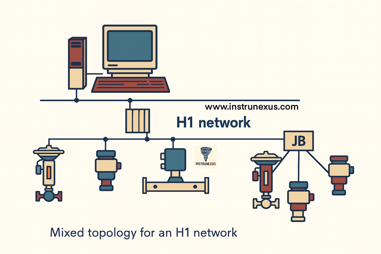
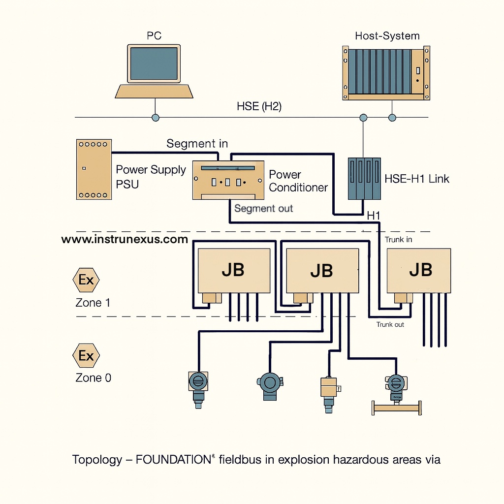
- FF H1: This is the most common implementation for connecting field devices. It operates at a speed of 31.25 kbit/s over a single twisted-pair of wires. A key feature of H1 is that it provides both communication and DC power to the connected devices over the same two wires, making it inherently suitable for intrinsically safe applications in hazardous environments.
- FF HSE (High-Speed Ethernet): Operating at 100 or 1000 Mbit/s, HSE is an Ethernet-based backbone used to connect multiple H1 segments (via linking devices), controllers, and host systems. It serves as the high-speed network for integrating the field-level H1 networks with the plant-wide control system.
Key Feature – Distributed Control (“Control in the Field”)
The defining characteristic of FOUNDATION Fieldbus is its ability to execute control strategies directly in the field devices, a concept known as “Control in the Field” (CIF). This is achieved through a standardized set of function blocks (e.g., AI for Analog Input, PID for Proportional-Integral-Derivative control) that reside within the microprocessors of the field instruments. An entire control loop, such as a flow control loop, can be configured to run between a transmitter and a valve on the same H1 segment, completely independent of the central DCS or PLC. This distribution of intelligence dramatically increases system reliability; if the host controller or its network connection fails, the field-level control loop can continue to operate autonomously, preventing a process upset or shutdown.
Communication Model
To ensure the predictable, timely delivery of data required for closed-loop control, FF H1 employs a deterministic, scheduled communication model. A device known as the Link Active Scheduler (LAS) controls the bus, granting permission to each device to transmit data at a precisely scheduled time within a repeating “macrocycle”. This prevents data collisions and guarantees that critical control data arrives with minimal jitter. The protocol also supports unscheduled (acyclic) communication for less time-critical data like diagnostics and configuration, as well as peer-to-peer communication, which allows devices to exchange data directly without passing through a host.
3.3. PROFIBUS (Process Field Bus)
PROFIBUS was developed in Germany, with significant promotion from Siemens, and is now managed by PROFIBUS & PROFINET International (PI). It is also a major open standard under IEC 61158 and has the largest installed base of any fieldbus worldwide.
Variants
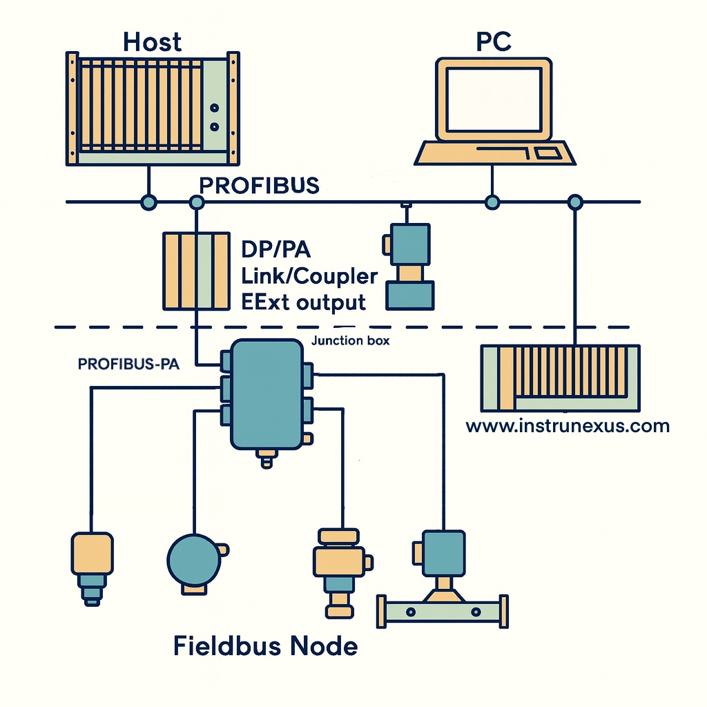
- PROFIBUS DP (Decentralized Peripherals): This is the high-speed workhorse of the PROFIBUS family, primarily used in factory and manufacturing automation. It operates over an RS-485 physical layer at speeds from 9.6 kbit/s up to 12 Mbit/s. PROFIBUS DP is optimized for fast, cyclic communication between a central controller (master) and its distributed I/O, drives, and sensors (slaves).
- PROFIBUS PA (Process Automation): This variant is designed for the specific needs of process automation. It uses the same IEC 61158-2 physical layer as FF H1, operating at a fixed 31.25 kbit/s and providing both power and communication over a single two-wire cable for use in intrinsically safe areas. PROFIBUS PA devices are not connected directly to a controller; instead, a PA segment is linked to a high-speed PROFIBUS DP network via a device called a coupler or link, which acts as a gateway and power supply.
Communication Model
PROFIBUS primarily operates on a master-slave communication model. The master device (e.g., a PLC) cyclically polls each slave device on the network to read inputs and write outputs. In systems with multiple masters, a token-passing procedure is used, where masters pass a “token” message between them to grant exclusive access to the bus. While highly efficient for factory automation, this polling-based model is generally considered less deterministic for the precise timing required by some advanced process control loops compared to the fully scheduled approach of FOUNDATION Fieldbus.
The historical development of these two protocols reveals a divergence in design philosophy driven by their target industries. PROFIBUS, with its fast DP variant and efficient master-slave architecture, was optimized for the high-speed, cyclic I/O scanning required in discrete manufacturing and factory automation. In contrast, FOUNDATION Fieldbus, with its intrinsic safety, scheduled communication, and groundbreaking “Control in the Field” capability, was tailored for the high-reliability, continuous control demands of the process industries like oil and gas, refining, and chemicals.
3.4. Fieldbus vs. 4-20 mA: A Comparative Analysis
The transition from 4-20 mA to Fieldbus technologies offers a clear set of trade-offs.
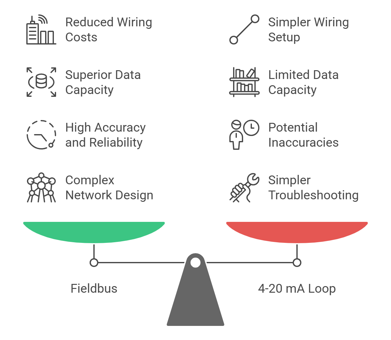
- Wiring & Cost: Fieldbus provides a clear advantage in new (“greenfield”) installations by drastically reducing the amount of wiring, conduit, junction boxes, and I/O cards needed, which in turn lowers material and labor costs.
- Data & Diagnostics: Fieldbus is vastly superior in data capacity. A single Fieldbus device can transmit multiple process variables, calculated values, and a wealth of advanced diagnostic and status information, whereas a 4-20 mA loop is limited to a single process value.
- Accuracy & Reliability: As an all-digital system, Fieldbus eliminates the potential for inaccuracies from A/D and D/A conversions. It also provides robust error-checking and can report on the health and quality of its own data, making it more reliable than an analog signal that can drift due to EMI or grounding problems without any explicit indication of a fault.
- Complexity: The primary disadvantage of Fieldbus is its complexity. Designing a Fieldbus network requires specialized knowledge of segment calculations, power requirements, terminators, and addressing. Troubleshooting is also more complex, often requiring specialized tools like a bus analyzer instead of a simple multimeter.
This very complexity has been a significant barrier to the universal adoption of Fieldbus, particularly in existing (“brownfield”) plants. The promised capital expenditure savings on wiring were often perceived to be offset by increased operational expenditure on specialized engineering, training, and maintenance. This economic trade-off is a primary reason why the technologically simpler 4-20 mA and HART standards remain dominant today, representing a “good enough” solution for a vast number of applications.
Part 4: The Untethered Plant – Wireless Instrumentation Standards
The evolution of industrial communication took another significant leap with the development of wireless standards. This move was driven by a powerful economic imperative: to capture valuable data from assets where the cost and complexity of running physical wires were prohibitive. Wireless instrumentation does not aim to replace wired networks for all applications, particularly for critical, high-speed control. Instead, it serves as a complementary technology, extending the reach of automation into new areas, enhancing operational visibility, and increasing plant safety and efficiency in a highly flexible and cost-effective manner.
4.1. The Motivation for Wireless
The business case for industrial wireless is compelling and centers on several key advantages over traditional wired solutions:
- Cost Reduction: The most significant driver is the elimination of costs associated with engineering, materials (wires, conduit, cable trays), and labor for installation. For many measurement points, the cost of wiring can exceed the cost of the instrument itself. Wireless makes it economically feasible to monitor previously “stranded” assets, where the value of the data did not justify the high cost of wiring.
- Flexibility and Speed of Deployment: Wireless devices can be installed and commissioned in a fraction of the time required for wired instruments. They offer unparalleled flexibility, enabling monitoring in remote locations, on rotating equipment (e.g., kilns), or in areas where physical access is difficult or hazardous.
- Enhanced Safety and Environmental Monitoring: Wireless sensors can be easily deployed for safety applications like leak detection or monitoring pressure relief valves. They also reduce the need for personnel to perform manual rounds in potentially hazardous areas to collect data, thereby improving worker safety.
4.2. WirelessHART (IEC 62591)
WirelessHART, ratified as IEC 62591, is an extension of the widely adopted HART protocol and is managed by FieldComm Group. It has become the leading wireless standard in the process automation industry, designed to be simple, reliable, and secure. It operates in the license-free 2.4 GHz Industrial, Scientific, and Medical (ISM) radio band.
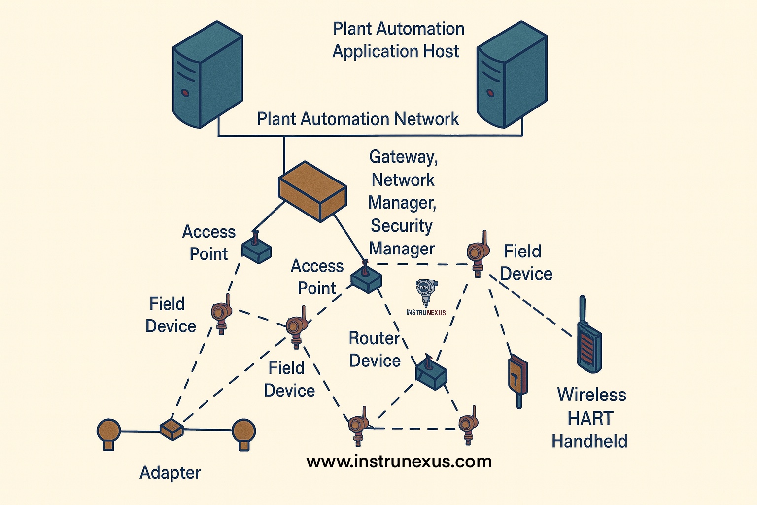
Network Architecture – Full Mesh Network
The defining feature of WirelessHART is its use of a time-synchronized, self-organizing, and self-healing mesh network architecture. In this topology:
- Every device in the network can serve as a router for data from other devices.
- This creates multiple redundant communication paths from each instrument back to the network gateway.
- If a communication path is blocked or degraded due to an obstruction or radio interference, the network automatically and dynamically reroutes the message through an alternative path, ensuring extremely high data reliability (often >99.9%).
Communication Method – TDMA and FHSS
To ensure robust and reliable communication in the often-congested 2.4 GHz band, WirelessHART employs a dual approach:
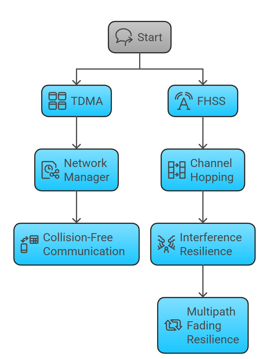
- Time Division Multiple Access (TDMA): Communication is organized into strict 10ms time slots. The Network Manager assigns specific time slots to each device for transmission, which prevents data packets from colliding with each other on the network. This provides deterministic, collision-free communication.
- Frequency Hopping Spread Spectrum (FHSS): The protocol continuously and pseudo-randomly hops across the 15 available channels within the 2.4 GHz band for each transmission. This technique, also known as channel hopping, makes the network highly resilient to interference from other wireless systems (like Wi-Fi) and from multipath fading, a common radio propagation issue in industrial plants.
Security
Security is a foundational element of the WirelessHART standard. It employs robust, multi-layered security measures to protect the network and its data, including:
- 128-bit AES Encryption: All data transmissions are encrypted to ensure confidentiality.
- Message Integrity Codes (MIC): Each message is checked to ensure it has not been tampered with during transmission.
- Device Authentication: New devices must possess a unique and correct “join key” to be authenticated by the Network Manager before they are allowed to join the network.
4.3. ISA100.11a (IEC 62734)
Developed by the International Society of Automation (ISA), the ISA100.11a standard (ratified as IEC 62734) was designed to be a more flexible and comprehensive framework for a wide variety of industrial wireless applications, beyond just process instrumentation. It also operates in the 2.4 GHz ISM band.
Network Architecture – Flexible Topologies
A key difference from WirelessHART is ISA100.11a’s support for multiple network topologies. While it can operate in a mesh configuration, it also supports star and cluster-tree topologies. This flexibility allows network architects to optimize the design for specific application requirements, such as minimizing power consumption for battery-powered devices in a star configuration.
Communication and Protocols
ISA100.11a also utilizes TDMA for scheduled communication and channel hopping for interference mitigation. A significant differentiator is its native support for open IT standards, particularly IPv6, through the 6LoWPAN adaptation layer. This makes ISA100.11a inherently more aligned with standard enterprise networks and the broader Internet of Things (IoT), facilitating easier integration with IP-based systems and future-proofing the architecture.
Security
Like WirelessHART, ISA100.11a incorporates robust security measures, including 128-bit AES encryption, data integrity checks, and strong device authentication, which are managed by a dedicated Security Manager entity within the network architecture.
The design philosophies of these two leading standards reflect a fundamental divergence. WirelessHART was conceived as a direct, wireless extension of the existing HART protocol, prioritizing a simple migration path and ease of use for the vast existing HART user base. In contrast, ISA100.11a was envisioned as a more versatile and future-proofed framework built on open IT standards, prioritizing flexibility and interoperability with a broader ecosystem of applications at the cost of greater initial complexity.
4.4. Challenges and Limitations of Industrial Wireless
Despite their advantages, wireless instrumentation systems present a unique set of challenges:
![]()
- Power Constraints: The majority of wireless field devices are battery-powered to achieve a truly “wire-free” installation. This imposes constraints on the data update rate; faster updates consume more power and shorten battery life. Consequently, applications must be carefully evaluated, and a robust battery management and replacement strategy is a critical part of maintenance.
- Latency and Bandwidth: Wireless networks inherently have higher latency and lower bandwidth compared to their wired counterparts. While protocols like WirelessHART provide deterministic communication suitable for many monitoring and even some closed-loop control applications, they are generally not appropriate for high-speed, safety-critical, or tight control loops that require millisecond response times.
- Coexistence and Interference: The 2.4 GHz band is a shared and unregulated space, populated by Wi-Fi, Bluetooth, and other wireless technologies. While FHSS and other techniques provide strong coexistence capabilities, careful network planning, including channel blacklisting, is often required in dense wireless environments to ensure reliable performance.
- Environmental Factors: The physical environment of an industrial plant, with its abundance of metal structures, moving equipment, and dense infrastructure, can significantly impact radio signal propagation. This can lead to signal reflection, absorption, and diffraction, requiring careful network design, placement of devices, and sometimes the use of dedicated repeater nodes to ensure robust network coverage.
Ultimately, the adoption of industrial wireless is not driven by its ability to replace wired systems for core process control. Instead, its value lies in unlocking economic benefits from previously un-instrumented or manually monitored assets. It is largely a complementary technology that expands the scope and reach of automation for reliability, safety, and efficiency applications where the cost of wiring was the primary barrier to implementation. This reframes the “wired vs. wireless” debate from one of replacement to one of strategic augmentation.
Part 5: Comparative Analysis and Future Outlook
The evolution of instrumentation signal standards from simple analog loops to complex wireless mesh networks reflects a continuous pursuit of greater efficiency, reliability, and data visibility in industrial operations. Each standard represents a set of engineering trade-offs, balancing performance, cost, complexity, and compatibility. A holistic comparison reveals the distinct roles each technology plays, while an analysis of current trends points toward a future of converged, data-centric industrial networks.
5.1. Comprehensive Comparison of Standards
The selection of an appropriate signal standard is a critical design decision that depends heavily on the specific application, whether it is a new (greenfield) project or an upgrade to an existing (brownfield) facility, and the desired balance between performance and cost. The following table provides a comparative summary of the standards discussed.
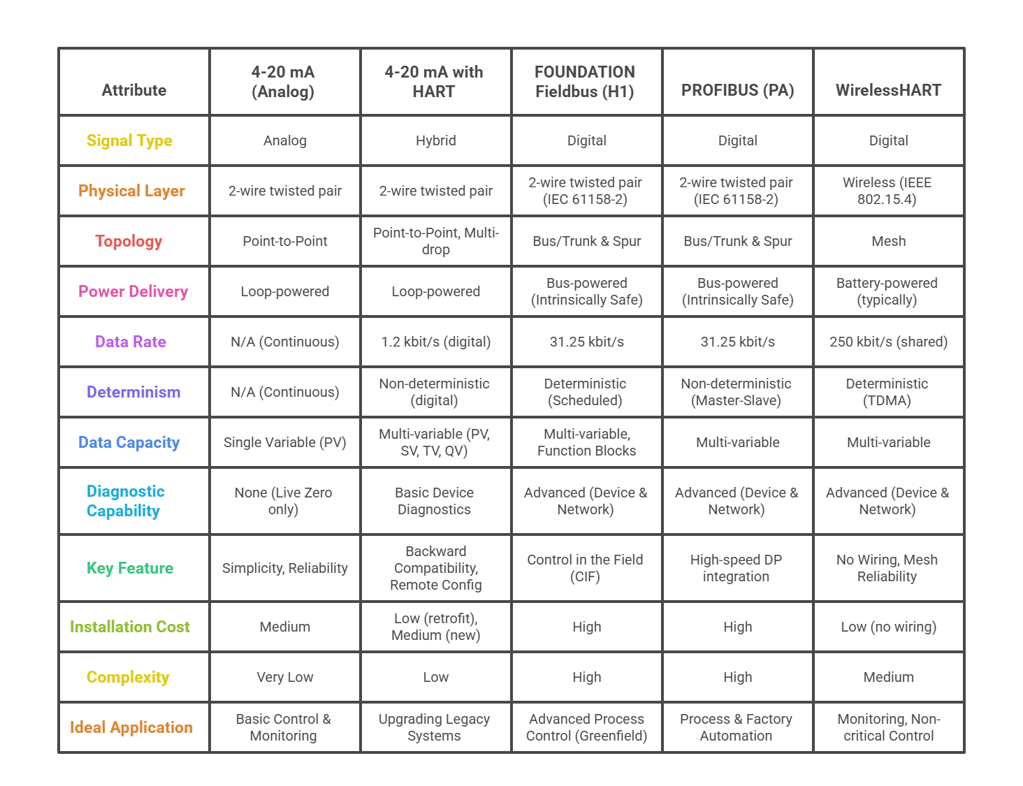
This matrix distills the core findings of the preceding analysis into a practical decision-making tool. It highlights that while technologically simpler standards like 4-20 mA and HART offer lower complexity and cost for basic applications or retrofits, more advanced digital protocols like FOUNDATION Fieldbus and WirelessHART provide significantly greater data capacity, diagnostic insight, and system-level capabilities, albeit at the cost of increased complexity and, in some cases, higher initial investment.
5.2. The Rise of Industrial Ethernet
The historical landscape of serial-based Fieldbuses is steadily giving way to protocols built upon standard Ethernet (IEEE 802.3). Industrial Ethernet protocols such as PROFINET, EtherNet/IP, and EtherCAT represent the next phase in the evolution of plant-floor networking.
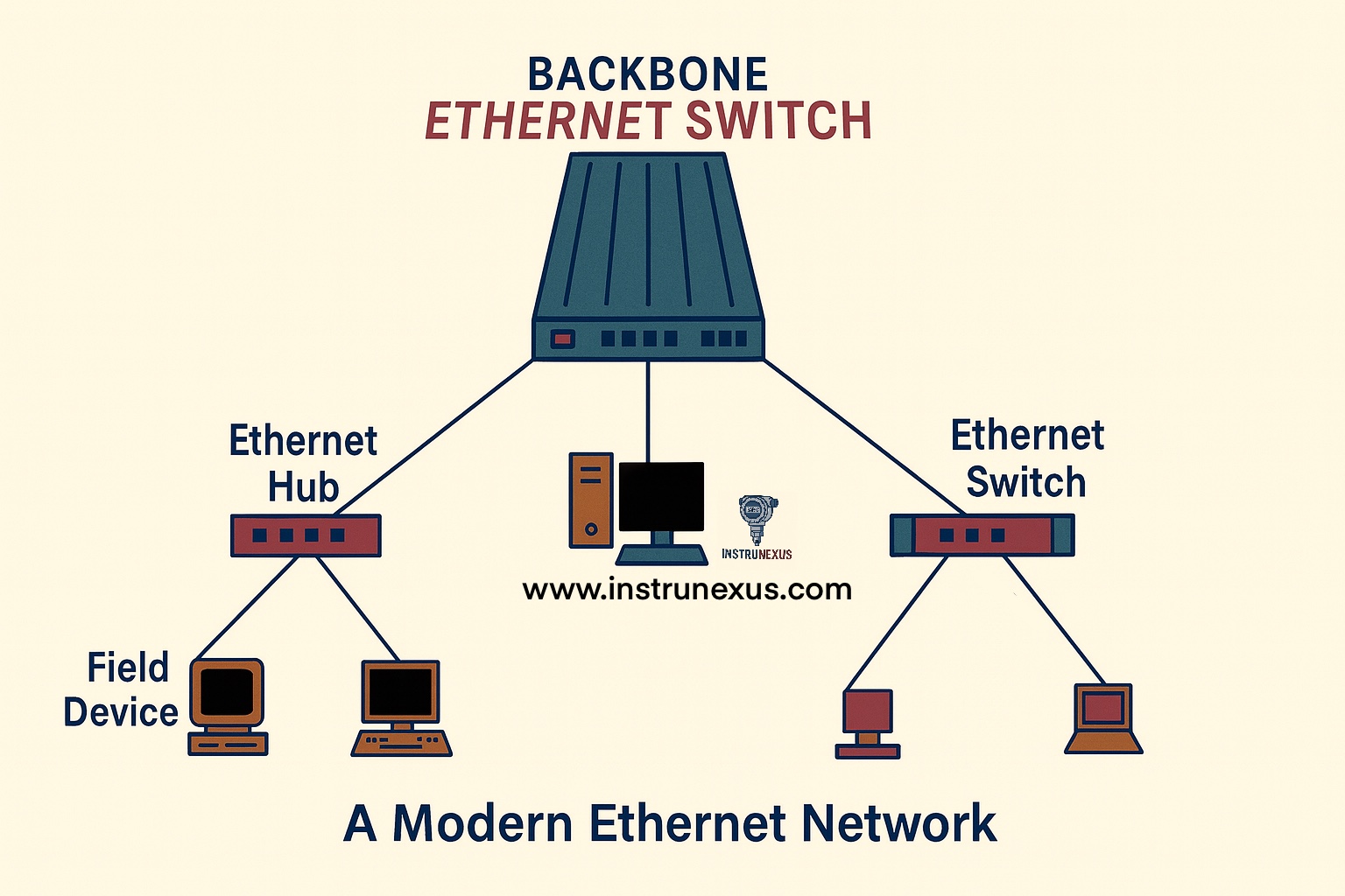
The move to an Ethernet physical layer is driven by several compelling advantages:
- Higher Bandwidth: Industrial Ethernet offers speeds of 100 Mbit/s, 1 Gbit/s, and beyond, orders of magnitude faster than traditional Fieldbuses.
- Larger Data Packets and Address Space: It allows for the transmission of more complex data and supports a virtually unlimited number of network nodes.
- Seamless IT/OT Integration: Using the same foundational technology as enterprise IT networks simplifies vertical integration, allowing data to flow more easily from the plant floor to business-level systems.
- Use of Commercial Off-the-Shelf (COTS) Hardware: Leveraging standard Ethernet switches, cables, and network interface cards reduces costs and benefits from the rapid innovation cycle of the much larger IT market.
A primary challenge for using standard Ethernet in control applications is its non-deterministic nature. Standard Ethernet uses a contention-based access method (CSMA/CD) that operates on a “best effort” basis, which is unsuitable for applications requiring predictable, guaranteed data delivery times. Industrial Ethernet protocols overcome this limitation by implementing specialized mechanisms at the data link or application layers to ensure real-time performance. For example, PROFINET uses dedicated Real-Time (RT) and Isochronous Real-Time (IRT) communication channels that bypass the standard TCP/IP stack to prioritize and schedule time-critical data packets.
5.3. The Future: IIoT, Industry 4.0, and Converged Networks
The trajectory of industrial communication points toward a future of unified, intelligent, and secure networks, driven by the principles of the Industrial Internet of Things (IIoT) and Industry 4.0. This future will likely be shaped by two transformative technologies: Time-Sensitive Networking (TSN) and OPC Unified Architecture (OPC UA).
Time-Sensitive Networking (TSN)
TSN is not another industrial protocol but rather a set of IEEE 802 standards that enhance standard Ethernet to provide true determinism at the data link layer (Layer 2). By standardizing mechanisms for time synchronization (IEEE 802.1AS), traffic scheduling (IEEE 802.1Qbv), and reliability (IEEE 802.1CB), TSN makes it possible for time-critical control traffic, high-bandwidth video streams, and standard IT data to coexist and share the same physical network infrastructure without interfering with one another. TSN has the potential to unify the fragmented landscape of Industrial Ethernet protocols, allowing them to operate over a common, interoperable, and deterministic network backbone.
OPC Unified Architecture (OPC UA)
While TSN addresses how data is moved, OPC UA addresses what the data means. OPC UA is a secure, platform-independent, service-oriented architecture for information modeling and data exchange. It provides a standardized way for disparate devices and applications—from field sensors to PLCs to cloud-based analytics platforms—to discover each other and exchange data in a structured, context-rich format. Its role is to act as a universal translator, enabling seamless vertical and horizontal integration across all levels of the automation pyramid and breaking down the data silos that have traditionally separated Operational Technology (OT) from Information Technology (IT).
The entire history of industrial communication can be viewed as a relentless progression toward moving more data, more reliably, and more cost-effectively. This progression is marked by increasing layers of abstraction: from the physical current of 4-20 mA, to a data overlay in HART, to a packetized network with Fieldbus, to an IP-based network with Industrial Ethernet, and finally to a standardized information model with OPC UA. Each step decouples the application from the underlying hardware, enhancing flexibility and interoperability.
The future of industrial networking is therefore not about a single “winner” protocol that replaces all others. Instead, it is about a unified infrastructure, likely based on Ethernet with TSN, that can accommodate multiple protocols and traffic types. Legacy protocols like HART and Fieldbus will not disappear; their vast installed bases ensure their relevance for decades to come. However, their role will evolve. They will increasingly be encapsulated or interfaced via gateways into this converged network, acting as data sources for a larger, IP-based ecosystem. The primary focus of innovation is shifting from the physical and data link layers—the domain of the “bus wars”—to the information modeling, security, and application layers, which are the critical enablers for the data-driven, interconnected factories of Industry 4.0.
Superb and very comprehensive. A must know contents for an Instrument Engineer. Thanks for your time and efforts.
This is superb. A must-know for Systems Integration, Automation, Instruments, and Control Systems Engineers.
This is excellent, well-detailed nd explanatory.