
The Three-Phase Separator: A Comprehensive Analysis of Principles, Design, and Advanced Operations
I. Introduction to Three-Phase Separation
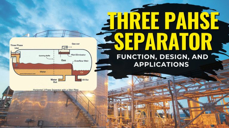
1.1. Purpose and Function
A three-phase separator is a critical piece of equipment in the industrial processing of raw hydrocarbon fluids. Its primary function is to separate a produced well stream into its three constituent components: gas, oil, and water. Widely employed in the oil and gas industry, these vessels are also referred to as free-water knockouts (FWKO) due to their role in the initial removal of free water from the crude oil stream. Their operation is indispensable in various processes, including oilfield production, natural gas processing, and petroleum refining.
The strategic benefits of effective three-phase separation extend far beyond simple physical segregation. By conditioning the produced fluid stream at the wellhead, these vessels ensure the accurate measurement and allocation of production fluids, which is vital for commercial operations. Furthermore, by removing corrosive and problematic components like water and gas, a well-functioning separator mitigates the environmental impact of operations, reduces mechanical stress on downstream equipment such as pipelines and storage facilities, and prolongs their operational lifespan. This process also serves to minimize the emission of harmful gases and reduces safety hazards, such as the risk of explosions, that can arise from the presence of unseparated gas. A properly selected and managed separator acts as a foundational element of the entire production chain, ensuring integrity, safety, and economic viability.
1.2. Fundamental Principles: The Physics of Separation
The operation of a three-phase separator is founded on the principle of gravity separation, which leverages the inherent density differences between the constituent phases. When the fluid stream enters the vessel and its velocity is reduced, the components stratify based on their specific gravity. The lightest phase, gas, rises to the top, while the heaviest, water, settles to the bottom. A layer of oil forms in the middle, and any solid particles, such as sand, settle at the very bottom.
The physics of this process for liquid droplets is precisely defined by fluid dynamics. The separation of a liquid droplet from a continuous fluid phase is primarily governed by Stokes’ Law, a fundamental criterion in separator design. This law describes the terminal settling velocity () of a spherical particle in a laminar flow regime. The equation for this can be expressed as:
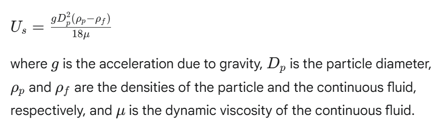
The relationship articulated by Stokes’ Law highlights a critical engineering challenge: a droplet’s settling velocity is directly proportional to the square of its diameter and inversely proportional to the viscosity of the continuous phase. This physical relationship explains why fine, small droplets and viscous fluids require a significantly longer time to separate, a critical design parameter known as retention time. Without sufficient time, these fine particles will not fully separate, leading to product contamination and reduced efficiency.
II. Separator Design, Typology, and Components
2.1. Vessel Orientation: Horizontal vs. Vertical
The two primary configurations for three-phase separators are horizontal and vertical, each with distinct advantages tailored to specific operational requirements.
Horizontal Separators: These are generally preferred for streams with high liquid flow rates and for situations requiring effective three-phase separation. The elongated shape provides a larger horizontal cross-sectional area, which translates to an increased liquid-liquid settling section. This greater surface area is particularly beneficial for achieving a clear separation between the oil and water phases. Additionally, horizontal vessels are typically easier to ship on skid assemblies and to install on-site.
Vertical Separators: These vessels are favored for applications with high gas-to-liquid ratios, such as in scrubber applications, and for fluid streams that contain a significant amount of sand, mud, or other solid particles. The vertical design makes it easier to clean out solid buildup from the bottom of the vessel. They are also less prone to the re-evaporation of liquids but require a larger diameter to achieve the same gas capacity as their horizontal counterparts.
The selection of a specific vessel orientation is not arbitrary; it is an engineering decision based on a careful analysis of the well stream’s composition. For instance, a high-liquid-rate stream necessitates the larger settling area of a horizontal vessel, while a stream with a high concentration of solids or paraffin favors the easier clean-out capabilities of a vertical separator. This shows how separator design is a direct and calculated response to the intrinsic properties of the fluid being processed.
2.2. Core Internal Components
Regardless of orientation, three-phase separators rely on a number of key internal components to facilitate efficient separation.
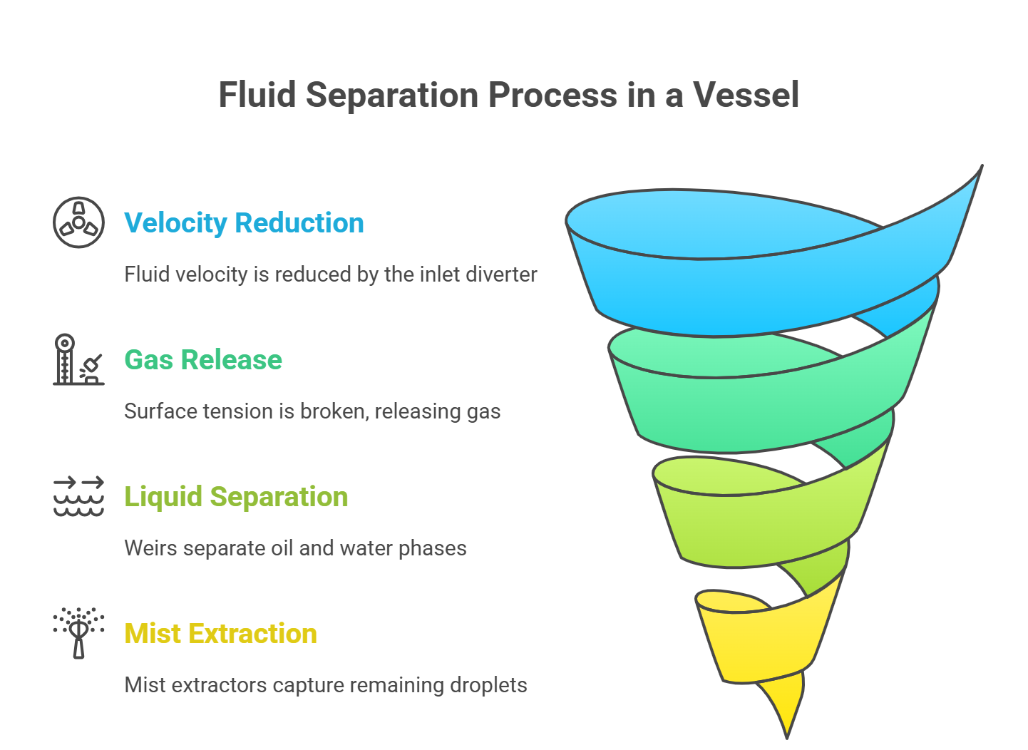
Inlet Diverter: Upon entering the vessel, the fluid stream immediately strikes an inlet diverter plate. This initial impact and sudden change in direction serves two crucial purposes: it rapidly reduces the fluid’s velocity and dissipates its momentum, and it breaks the surface tension of the liquid, which promotes the initial release of bulk gas from the liquid stream. Different types of diverters, such as simple plates, half pipes, or cyclonic devices, are selected based on the momentum and characteristics of the incoming flow.
Weirs and Oil Buckets: Weirs are physical barriers used to manage the liquid-liquid interface inside the vessel. They function by creating a barrier over which the lighter oil phase flows, while the heavier water phase is trapped below. In some designs, an oil bucket or pail is used in conjunction with a weir to collect the separated oil. The height of the weir is a critical design parameter as it directly determines the oil level within the vessel.
Mist Extractors (Demisters): Located at the gas outlet, a mist extractor is a final-stage polishing device. It is designed to capture and coalesce tiny liquid droplets (mist) that were not removed during the initial gravity-based separation. These devices, often made of wire mesh or vane packs, are essential for preventing liquid carryover into the gas stream, which could damage downstream equipment like compressors and dehydration units.
Level and Pressure Controllers: These instruments are the operational core of the separator’s automated control system. Level controllers continuously monitor the height of the oil-water interface and the liquid-gas interface. They send signals to dump valves that open or close to release the separated fluids as needed, ensuring that the interface levels are maintained at optimal heights for continuous, stable separation. A back-pressure control valve regulates the gas flow and maintains constant pressure within the vessel.
2.3. Comprehensive Typology of Designs
The internal components can be arranged in several common configurations, each representing a specific design approach.
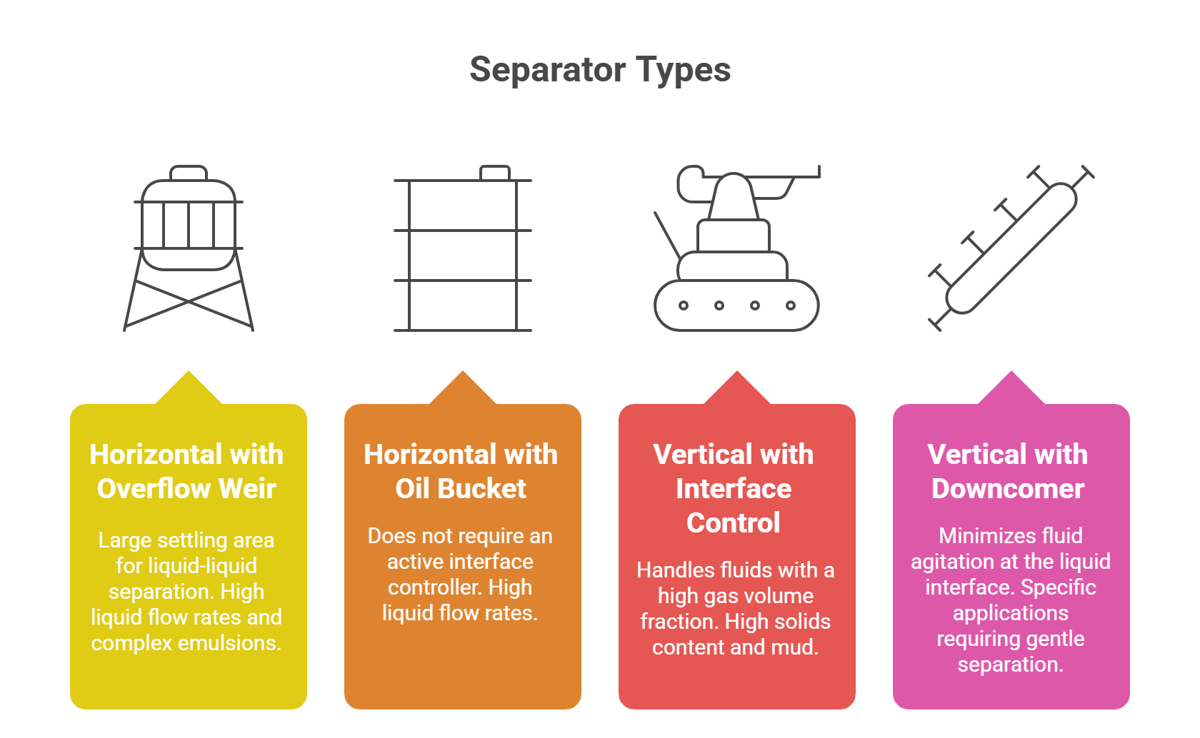
Horizontal with Overflow Weir: The most common design for three-phase separation. Fluid enters and is initially separated by an inlet diverter. The oil and water layers separate, and an interface level controller signals a dump valve to release water to maintain the oil-water level. Oil spills over the overflow weir, where a separate level controller manages its level and operates a dump valve.
Horizontal with Oil Bucket and Water Weir: This design is unique in that it eliminates the need for an active oil-water interface controller. The oil separates and flows over a weir plate into an oil bucket. Water, being heavier, flows under the oil bucket and over a separate water weir.
Vertical with Interface Control: In this configuration, fluid enters and hits an inlet diverter plate, which separates the bulk of the gas and directs the emulsion down the side wall to minimize disturbance. A splash guard is often used to further minimize agitation and protect the interface level controller from false readings. Both the oil and water levels are controlled by separate level controllers that operate corresponding dump valves.
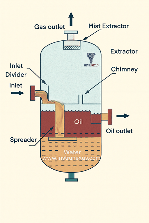
Vertical with a Downcomer and Spreader: This design utilizes a downcomer pipe that sends the liquid through the oil-gas interface to prevent agitation. The outlet of the downcomer, or spreader, is positioned at the oil-water interface. The water, being heavier, settles, while the oil rises. A weir controls the oil level, and a level controller manages the water.
A summary of the primary configurations and their key features is provided in the following table.
Table 1: Separator Typology and Key Components
III. Performance Variables and Operational Principles
3.1. The Science of Separation: Fluid Dynamics and Droplet Behavior
The efficiency of a three-phase separator is fundamentally linked to the behavior of the fluid phases and, in particular, the size of liquid droplets. As established by Stokes’ Law, separation performance is highly dependent on droplet size. Smaller particles settle or rise more slowly, meaning they require a longer time in the vessel to be fully separated. This is why a separator’s efficiency is often described in terms of a “critical diameter,” which represents the smallest droplet size that can be completely separated under a given set of operating conditions. Any droplets smaller than this critical diameter will likely remain in the fluid stream, leading to contamination.
3.2. Impact of Critical Variables
The separator’s performance is influenced by an interdependent system of variables that must be carefully managed.
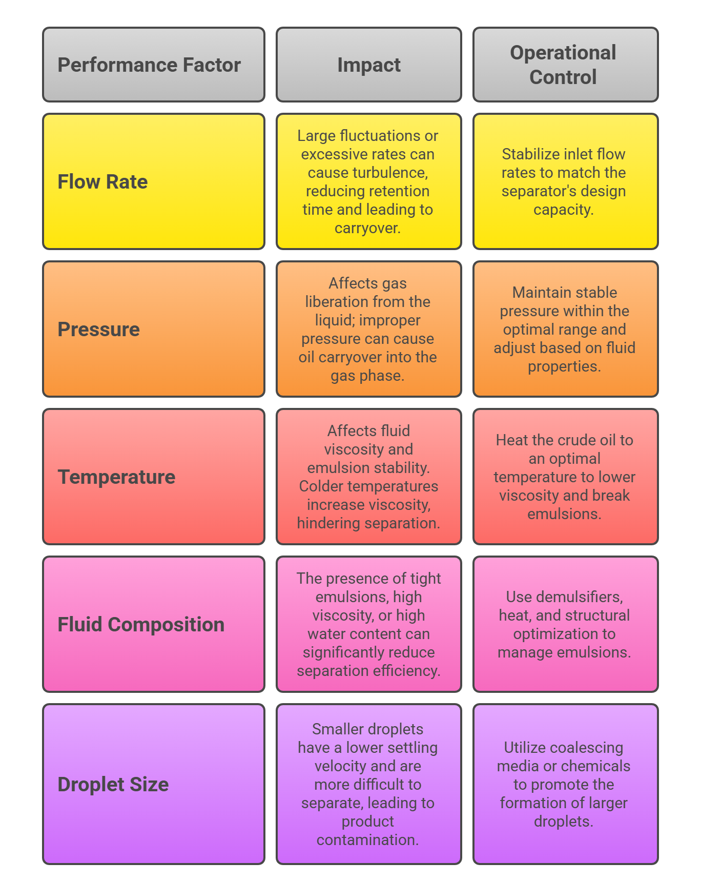
Flow Rates: The volume of fluid entering the separator directly impacts its efficiency. Fluctuating or excessively high inlet flow rates can overwhelm the separator’s capacity, increasing internal turbulence and reducing the effective retention time. This can cause the liquid phases to mix and result in oil, water, or gas carryover.
Pressure and Temperature: The operating pressure and temperature are crucial as they affect the physical properties of the fluids. Higher temperatures can lower the viscosity of oil, making it easier for water droplets to settle out of it. Pressure, on the other hand, governs the liberation of gas from the liquid stream. If pressure is too low, it can hinder oil-gas separation, while if it is too high, it can lead to oil and gas mixing in the vessel. The relationship between these factors is a complex one, as a change in one parameter can necessitate an adjustment in another to maintain optimal separation performance.
Fluid Characteristics: The intrinsic properties of the fluid are paramount. The API gravity and viscosity of the crude oil directly influence settling velocity, as described by Stokes’ Law. The presence of tight emulsions—where oil and water are finely mixed and stabilized by impurities—can significantly reduce separation efficiency. These emulsions often require pre-treatment with chemicals known as demulsifiers and the application of heat to break their bonds and facilitate separation.
3.3. The Crucial Role of Retention Time
Retention time, also known as residence or detention time, is a key metric for separator performance. It is defined as the average duration a fluid is retained within the liquid section of the separator at a given flow rate. This time is essential for allowing the gravitational forces to fully separate the gas bubbles from the liquid and the liquid droplets from each other.
For three-phase separators, the retention time is particularly critical and is generally longer than that required for a two-phase separator. This is because the separation of oil and water, which may be more thoroughly mixed and emulsified, requires a greater period of quiescence to achieve a clean interface. Retention time can be calculated by dividing the liquid volume inside the vessel by the liquid flow rate. Typical values for three-phase separation range from a few minutes to half an hour, depending on the fluid’s API gravity and temperature. The challenge in separator design is to balance efficiency with cost, as a longer retention time necessitates a larger, more expensive vessel.
A summary of the critical factors influencing separator performance and their corresponding operational considerations is provided below.
Table 2: Critical Factors and Their Impact on Separation Efficiency
IV. Operational Challenges, Safety, and Maintenance
4.1. Common Operational Faults and Solutions
Despite robust design, separators are susceptible to a variety of operational faults that can compromise efficiency and safety.
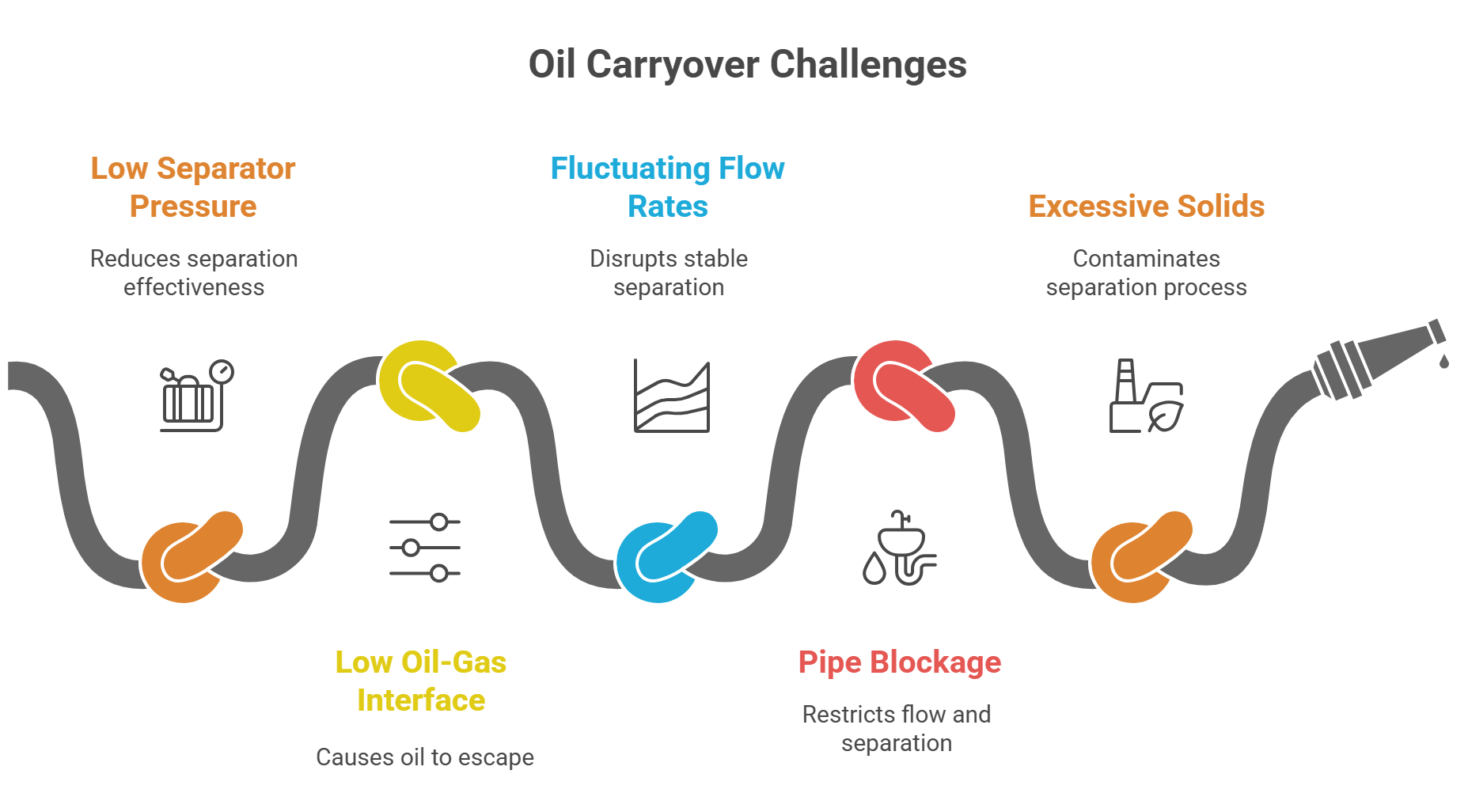
Oil Carryover into the Gas Phase: This occurs when oil is not properly separated and contaminates the gas stream. Causes include low separator pressure, a low oil-gas interface setting, or large fluctuations in liquid flow rates. The impact can be severe, leading to equipment contamination, compressor oil ingress, and even explosions. Solutions involve stabilizing the operating pressure, adjusting the interface level, and regulating the inlet flow rate.
Blockage in Outlet Pipes: The accumulation of solid particles or sediments can block the water and oil outlet pipes. This is often caused by excessive impurities in the incoming fluid or low fluid velocity that allows deposits to build up. Blockages can disrupt production and increase maintenance costs. The solutions include regular cleaning of pipes, optimizing piping design for smoother flow, and enhancing separator efficiency to minimize the accumulation of solids.
Unstable Separation Efficiency: An inconsistent separation performance can result in a degraded product stream. Root causes often include fluctuating inlet flow rates, worn or damaged equipment, or temperature swings in the crude oil. To address this, operators must stabilize the inlet flow, conduct regular inspections to replace damaged parts, and install temperature control devices to maintain the crude oil within its optimal range for separation.
4.2. Pre-Operation and Startup Procedures
A thorough pre-operation inspection and a systematic startup procedure are essential for ensuring a separator operates safely and reliably. Before startup, all valves, instruments, and pipelines must be inspected for leaks and functionality. A pressure test should be conducted according to pressure vessel standards to ensure the system can handle its rated working pressure.
The startup process follows a specific sequence:
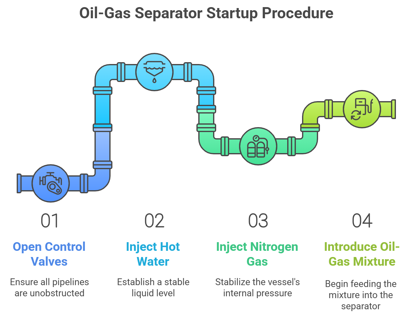
Valve Operation: Open control valves for pressure gauges and level gauges, ensuring all pipelines are unobstructed.
Hot Water Injection: Inject hot water into the vessel to establish a stable liquid level, carefully monitoring for leaks.
Gas Injection: Slowly inject nitrogen gas to stabilize the vessel’s internal pressure.
Oil-Gas Mixture Introduction: Gradually open the inlet valve to begin feeding the oil-gas mixture into the separator, adjusting the pressure as the flow increases to maintain stable operation.
4.3. Maintenance and Safety Protocols
Proactive maintenance is vital for extending the lifespan and ensuring the stable performance of a three-phase separator. This involves a shift from reactive, break-fix maintenance to a predictive approach.
Routine maintenance includes scheduled inspections of all components, regular cleaning to prevent the buildup of contaminants, and the calibration of controls and sensors. Advanced diagnostic tools are increasingly used to move beyond manual checks. Techniques such as vibration analysis can detect issues with bearings and other rotating components, while thermal imaging can identify solids accumulation or other issues by revealing temperature changes on the vessel’s exterior. These condition-based monitoring techniques allow operators to identify and address potential problems before they lead to a critical failure, optimizing uptime and reducing costly repairs.
Safety is a non-negotiable prerequisite for all operations. Operators must assess potential hazards and implement necessary safety measures, such as installing anti-leakage devices and emergency shutdown systems. The ongoing collection of operational data and maintenance records is also crucial, as this information provides a valuable historical context for future fault analysis and process optimization.
A summary of common faults and their solutions is provided in the following troubleshooting matrix.
Table 3: Troubleshooting Matrix for Common Separator Faults
V. Comparative Analysis: Separators and Related Technologies
The three-phase separator is a core component of a larger system for fluid processing. Its role is often complemented by other, more specialized pieces of equipment.
5.1. Three-Phase vs. Two-Phase Separators
The fundamental distinction between these two vessels lies in their function. A two-phase separator is designed to separate a hydrocarbon stream into two components: a total liquid stream and a gas stream. It is used when the produced fluid contains minimal or no water. In contrast, a three-phase separator performs the same initial gas-liquid separation but then further separates the liquid phase into its oil and water components. This makes the three-phase unit essential for processing well fluids where water is present and needs to be removed from the oil phase.
5.2. Differentiating Separators, Scrubbers, and Coalescers
Separators, scrubbers, and coalescers are often discussed together, but they serve distinct, though often complementary, roles within a production system.
Separators (Primary Separation): A three-phase separator is typically the first vessel in the process flow. It is designed to handle the high liquid load and perform the initial, or “bulk,” separation of the wellhead fluid.
Scrubbers (Downstream Polishing): A scrubber is a specialized type of two-phase separator used downstream from the main separator. Its purpose is to “scrub” small amounts of liquid carryover from a gas stream. Unlike a primary separator, a scrubber is designed to handle a very low liquid load.
Coalescers (Mist Removal): A coalescer is not a standalone vessel but a specific internal component found within a separator or scrubber. Its specific function is to enhance the separation of very fine liquid droplets (mist) that are too small to settle by gravity alone. It works by causing these tiny droplets to combine, or “coalesce,” into larger ones that can then be easily removed. A
coalescing filter, however, is a separate vessel that uses a specialized media to achieve ultra-high purity, often removing particles down to a sub-micron level.
This highlights a key principle of modern fluid processing: achieving high-purity separation often requires a multi-stage system. The three-phase separator handles the initial bulk separation, and the separated streams may then pass through a downstream scrubber or coalescer for a final polishing step.
VI. Innovations and Future Trends
The field of three-phase separation is undergoing a significant transformation driven by advancements in design, materials, and digital technology.
6.1. Advanced Design and Materials
Key industry developments include a shift towards modular, skid-mounted units, which are gaining preference over traditional fixed installations. These units offer greater flexibility, reduce installation costs, and can be more easily relocated as production needs change. Beyond external design, innovations are focusing on optimizing the internal components of the vessel itself. New materials are being used to reduce internal friction, allowing fluids to move more smoothly and quickly, which can reduce the necessary retention time without sacrificing separation quality. Advanced internal designs, such as multi-plate technology and coarse droplet promotion, are being explored to enhance droplet coalescence and improve efficiency.
6.2. The Dawn of Intelligent Separation
The most profound transformation is the integration of digital technologies to create “smart” and automated separation systems.
IoT and Real-Time Monitoring: The proliferation of IoT-enabled sensors allows for the real-time collection of data on critical parameters like pressure, level, and flow rates. This constant stream of data is the foundation for advanced automation and analytics.
AI and Machine Learning for Optimization: The data collected by sensors is being leveraged by artificial intelligence (AI) and machine learning (ML) models. These models can be used for predictive maintenance, anticipating potential equipment failures before they occur. Furthermore, AI can be used to dynamically adjust the operational parameters of the separator in real-time, responding to changes in fluid composition or flow rates. This moves control beyond fixed values based on past experience to a dynamic, adaptive system that maximizes efficiency and throughput. For example, data mining techniques can analyze vast datasets to determine how to best adjust a separator’s parameters to ensure proper separation and avoid operational anomalies.
Automated Control Systems: The integration of these digital components is leading to the development of sophisticated automated control systems. These systems, often built on Programmable Logic Controllers (PLCs) and Distributed Control Systems (DCS), can autonomously manage liquid levels, pressure, and fluid flows. This minimizes the risk of human error, improves the stability of the separation process, and ultimately reduces energy consumption and operational costs. The entire system is becoming a self-optimizing unit, moving from a reactive to a proactive and predictive state.
VII. Conclusion
A comprehensive understanding of the three-phase separator extends far beyond its basic function of separating oil, water, and gas. It requires a deep appreciation for the complex interplay between design principles, fluid dynamics, and a myriad of operational variables. The selection of a vessel—whether horizontal or vertical—is not a simple choice but a strategic engineering decision predicated on the specific properties of the produced fluid. Furthermore, the efficiency of the separation process is a function of critical factors such as flow rate, temperature, and viscosity, all of which are managed to ensure a sufficient retention time for phase segregation.
The analysis of common operational challenges reveals that separator management is a dynamic process that requires continuous monitoring and proactive maintenance to prevent faults such as oil carryover and pipe blockages. The industry is currently in a period of significant technological advancement, with the integration of smart instruments, AI, and automated control systems. These innovations are transforming the separator from a passive mechanical vessel into a proactive, intelligent component of the production system. Ultimately, the performance of the three-phase separator is a primary determinant of a production system’s overall safety, environmental compliance, and economic success.