
zIEC 61508: A Comprehensive Framework for Functional Safety in E/E/PE Systems
I. An Introduction to Functional Safety and the IEC 61508 Standard
1.1 Defining Functional Safety: Beyond Basic Reliability
In the modern landscape of automated and intelligent systems, the concept of safety has evolved beyond traditional mechanical safeguards and passive protection. The discipline of functional safety has emerged as a critical engineering field, concerned specifically with the active management of risk through automated systems. The International Electrotechnical Commission (IEC) defines functional safety as the “part of the overall safety relating to the EUC (Equipment Under Control) and the EUC control system which depends on the correct functioning of the E/E/PE safety-related systems, other technology safety-related systems and external risk reduction facilities”.
At its core, functional safety is predicated on the principle of active response. It relies on systems that can automatically detect a potentially dangerous condition and execute a pre-defined corrective action to prevent a hazardous event or mitigate its consequences. Simple examples are ubiquitous: a smoke detector triggering a sprinkler system, an elevator’s overspeed governor engaging the brakes, or an industrial boiler’s control system shutting off the fuel supply when a pressure sensor exceeds a critical threshold. This active nature distinguishes it from passive safety measures, such as fire-resistant doors or protective clothing, which perform their function without sensing or executing a response.
The discipline is built upon two fundamental engineering concepts that work in tandem. The first is the principle of reliability engineering: ensuring the system performs its intended function correctly under all specified conditions. The second, and more defining, is the principle of safety engineering: ensuring that if the system does fail, it does so in a predictable and acceptably safe manner—a concept often referred to as “fail-safe” design. Therefore, functional safety is not merely about preventing failures, but about managing their consequences to achieve a state of freedom from unacceptable risk.
The creation of a formal standard for functional safety, IEC 61508, marked a significant paradigm shift in how safety is engineered. Historically, safety engineering often relied on a reactive model, analyzing incidents after they occurred and implementing corrective measures. The increasing integration of complex, software-driven programmable electronics into safety-critical functions during the 1980s exposed the limitations of this approach. Software, in particular, introduced a new class of “systematic” failures—design flaws, coding errors, or specification mistakes—that could not be predicted or modeled by traditional hardware reliability metrics. The response to this challenge was to develop a proactive, evidence-driven methodology that treats safety not as a feature to be added on, but as an emergent property of a rigorously defined and executed process that spans the entire life of a system. This process-centric view acknowledges that in modern systems, safety is as much about managing information, documentation, and human factors as it is about managing physical hardware failures.
1.2 The Genesis and Purpose of IEC 61508: The Foundational “Mother” Standard
Published by the International Electrotechnical Commission, the standard IEC 61508, officially titled “Functional Safety of Electrical/Electronic/Programmable Electronic Safety-related Systems”, is the seminal international document that codifies the principles of functional safety. Often referred to by the acronym E/E/PE (for Electrical/Electronic/Programmable Electronic) or E/E/PES (for E/E/PE Systems), it provides a comprehensive framework for the specification, design, implementation, operation, and maintenance of safety-related systems.
The standard’s origins trace back to the mid-1980s, when the IEC established a task group to explore the feasibility of a generic standard for the use of programmable electronic systems in safety applications. This initiative was a direct response to the growing use of microprocessors and software in control systems where failure could have catastrophic consequences. The first edition of the standard was published in a series of parts between 1998 and 2000, with a technically revised second edition released in 2010.
IEC 61508 is widely regarded as the foundational, or “mother,” standard for functional safety. Its generic nature makes it applicable across all industries, serving as the default standard where no sector-specific alternative exists. More importantly, it was designed as a “basic safety publication,” a designation that obligates other IEC technical committees to use its principles as the basis for developing their own industry-specific standards. This has led to a harmonized ecosystem of standards for sectors such as process industries (IEC 61511), machinery (IEC 62061), and automotive (ISO 26262), all of which derive their core concepts from IEC 61508.
The primary objectives of the standard are multifaceted and ambitious:
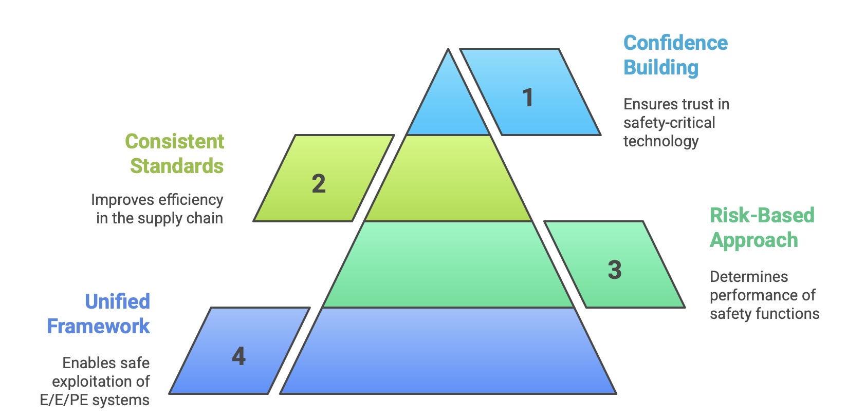
To provide a unified technical framework that enables the safe exploitation and technological development of E/E/PE systems.
To establish a risk-based approach for determining the required performance of safety functions.
To serve as a generic basis for the development of consistent sector- and product-specific standards, thereby improving efficiency in the supply chain.
To provide a means for users, developers, and regulators to gain confidence in the use of complex, computer-based technology in safety-critical roles.
1.3 Core Philosophy: A Risk-Based Approach to Safety (ALARP)
The philosophical cornerstone of IEC 61508 is its risk-based approach. The standard operates on the fundamental premise that achieving zero risk is impossible. Instead, the goal is to identify all foreseeable hazards and reduce the associated risks to a tolerable level. This tolerable level is not arbitrary; it is defined as a “risk which is accepted in a given context based on the current values of society”.
To bridge the gap between the inherent risk of a process and this tolerable risk level, the standard employs the principle of ALARP, which stands for “As Low As Reasonably Practicable”. The ALARP principle divides risk into three regions:
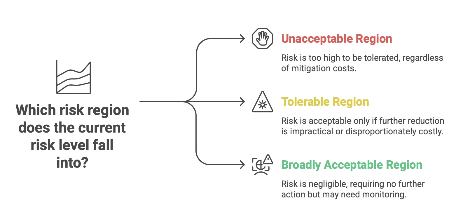
Unacceptable Region: The risk is so high that it cannot be tolerated, regardless of the cost of mitigation.
Tolerable Region (or ALARP Region): The risk is acceptable only if further risk reduction is impracticable or if the cost of reduction is grossly disproportionate to the safety benefit gained.
Broadly Acceptable Region: The risk is considered negligible and no further action is needed, although monitoring may be required.
This framework mandates that all risks in the unacceptable region must be reduced, and all risks in the tolerable region must be driven down until the cost of doing so becomes grossly disproportionate to the improvement. This systematic process ensures that safety measures are proportionate to the level of risk they are intended to control. It prevents both the under-engineering of high-risk scenarios and the over-engineering of low-risk ones, thereby achieving a state of optimal, cost-effective safety. The process begins with a thorough hazard and risk analysis to determine the amount of risk reduction required for each identified hazardous event. This required risk reduction then becomes the primary input for specifying the performance requirements of the safety functions designed to achieve it.
1.4 The Two Pillars: The Safety Lifecycle and Probabilistic Failure Management
To translate its risk-based philosophy into a practical engineering methodology, IEC 61508 is built upon two fundamental and complementary principles: the safety lifecycle and a probabilistic approach to managing failures. These two pillars form the standard’s comprehensive strategy for achieving and demonstrating functional safety.
The Safety Life Cycle: This is a structured engineering process, defined in the standard as a sequence of phases, that covers a safety-related system from its initial conception to its final decommissioning. This “cradle-to-grave” approach is designed to discover and eliminate design errors, specification omissions, and other human-factor mistakes throughout the development process. By mandating specific activities, documentation, and verification steps at each phase, the lifecycle provides a systematic framework for controlling systematic failures—those failures that are inherent in the design or implementation and can only be removed by a change in that design.
Probabilistic Failure Management: This principle addresses the reality that physical components will eventually fail in a random and unpredictable manner. The standard provides a probabilistic framework to account for the safety impact of these random hardware failures. It requires a quantitative analysis of a system’s design to determine its probability of failing in a dangerous manner. This analysis considers factors like component failure rates, architectural redundancy, and the effectiveness of diagnostic features. The results of this analysis are then compared against specific, numerically defined targets to ensure the system’s reliability is sufficient to meet its required level of risk reduction.
These two pillars are not independent; they are deeply interwoven throughout the standard’s requirements. The safety lifecycle dictates when and how the probabilistic analyses are performed, and the results of those analyses inform design decisions made within the lifecycle phases. Together, they provide a holistic methodology for managing both the predictable (process-related) and unpredictable (random) aspects of failure in safety-critical systems.
II. Deconstructing the Standard: An Analysis of IEC 61508’s Structure
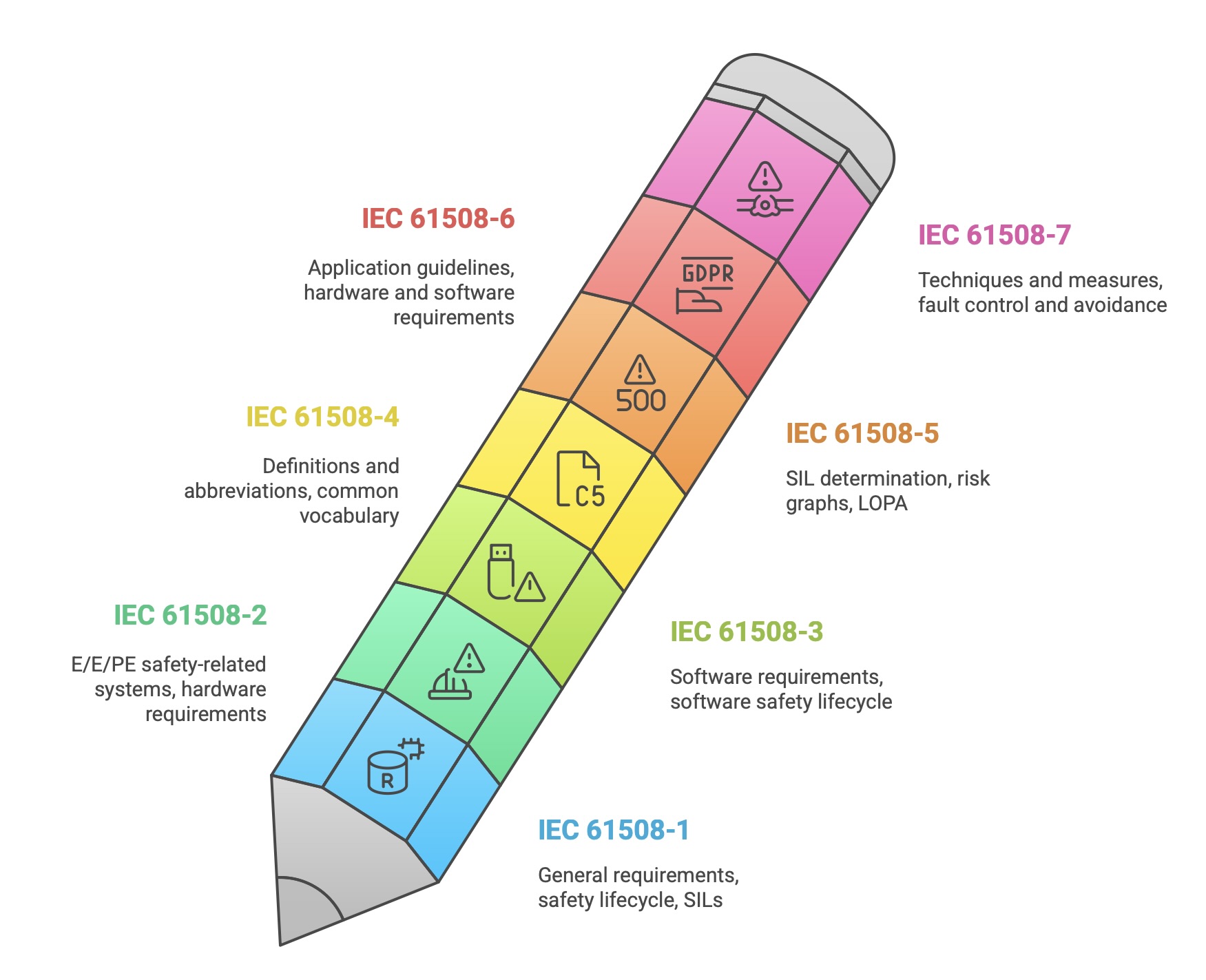
To effectively implement IEC 61508, it is essential to first understand its structure. The standard is a comprehensive, multi-part document designed to be navigated by various stakeholders, from system architects and hardware engineers to software developers and safety assessors. The current second edition (IEC 61508:2010) is organized into seven distinct parts, each with a specific purpose. An eighth part, IEC/TR 61508-0, was published in 2005 as a functional safety overview but is now considered obsolete with the release of the second edition.
2.1 Navigating the Parts: Normative vs. Informative Requirements
A critical distinction within the standard’s structure is between its normative and informative parts. This distinction clarifies which requirements are mandatory for claiming compliance and which are provided as guidance or examples.
Normative Parts (1, 2, 3, and 4): These parts contain the core requirements of the standard. Compliance with these requirements is mandatory to claim conformance with IEC 61508. Parts 1, 2, 3, and 4 are also designated as IEC Basic Safety Publications (BSPs). This special status means that other IEC Technical Committees are required to use these parts as the foundation when preparing their own product or application-specific standards that involve E/E/PE safety-related systems. This ensures a high level of consistency in principles and terminology across the entire IEC standards ecosystem.
Informative Parts (5, 6, and 7): These parts are intended as guidelines and do not contain any normative requirements. They provide examples of methods, techniques, and measures that can be used to satisfy the mandatory requirements laid out in the normative parts. While not mandatory, these sections are invaluable for practical implementation, offering detailed “how-to” information that helps interpret and apply the standard’s principles.
The standard’s architecture, which separates general framework requirements (Part 1) from the detailed hardware (Part 2) and software (Part 3) realization lifecycles, is a deliberate reflection of a classic systems engineering “V-model.” This structure inherently enforces a top-down design philosophy. The process begins on the left side of the “V” with the definition of the overall system and the decomposition of high-level safety goals into specific, allocated requirements for hardware and software subsystems, as mandated by Part 1. The development of these subsystems, detailed in Parts 2 and 3, occurs at the bottom of the “V”. The process then moves up the right side of the “V,” where the realized components are integrated, tested, and ultimately validated against the original overall safety requirements defined at the start of the project. This structure is not merely organizational; it is a mechanism that enforces traceability. It creates a verifiable chain of evidence from the highest-level safety concept down to individual lines of code and hardware components, and back up through the corresponding verification and validation reports. This traceability is a cornerstone of demonstrating compliance in high-integrity systems.
The following table provides a concise overview of the standard’s structure.
2.2 Part 1: General Requirements and the Overall Framework
IEC 61508-1 is the keystone of the entire series. It establishes the comprehensive management and technical framework within which all functional safety activities must be conducted. This part introduces the foundational concepts that are applied and detailed in the subsequent parts. Its key contributions include:
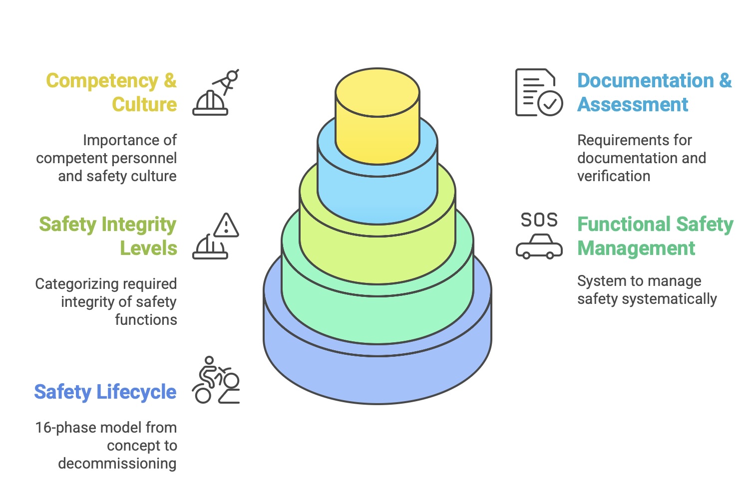
The Overall Safety Lifecycle: It defines the 16-phase model that structures all activities from concept to decommissioning.
Functional Safety Management (FSM): It mandates the creation and maintenance of a Functional Safety Management System (FSMS) to ensure safety is systematically managed throughout the lifecycle.
Safety Integrity Levels (SILs): It introduces the concept of SILs as the method for categorizing the required integrity of safety functions.
Documentation, Verification, and Assessment: It outlines the overall requirements for documentation structure, verification processes, and the need for periodic Functional Safety Assessments (FSAs) to confirm compliance.
Competency and Safety Culture: It stresses the importance of using competent personnel and fostering a strong safety culture within the organization.
Because it dictates the system-wide principles that apply to all engineering activities, Part 1 is significant for every stakeholder, including software developers who might otherwise focus solely on Part 3.
2.3 Part 2: Requirements for E/E/PE Safety-Related Systems (Hardware)
IEC 61508-2 translates the general requirements of Part 1 into specific, actionable requirements for the hardware elements of a safety-related system. This part is crucial for hardware designers and system integrators. It details a specific safety lifecycle for hardware development and provides rigorous requirements for controlling random hardware failures. Key topics covered in Part 2 include:
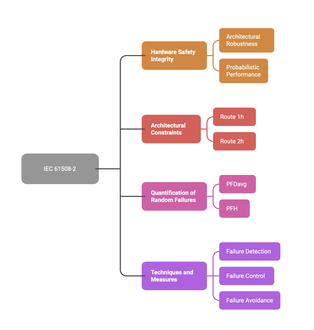
Hardware Safety Integrity: Defines the requirements for achieving a target SIL for hardware, focusing on architectural robustness and probabilistic performance.
Architectural Constraints: Specifies minimum levels of Hardware Fault Tolerance (HFT) based on the SIL and component characteristics. It introduces two alternative approaches, Route 1h and Route 2h, for demonstrating sufficient architectural robustness.
Quantification of Random Failures: Outlines the requirements for calculating probabilistic metrics like PFDavg and PFH, including the use of component failure rate data and accounting for diagnostic coverage.
Techniques and Measures: Recommends or highly recommends specific design and testing techniques for failure detection, control, and avoidance, graded by SIL.
2.4 Part 3: Software Requirements
IEC 61508-3 is dedicated entirely to software and is the primary reference for software engineers and developers working on safety-related systems. Given that software is a principal source of complex and difficult-to-detect systematic failures, this part is exceptionally detailed and process-oriented. It defines a complete software safety lifecycle that runs in parallel with the hardware lifecycle. Major requirements include:
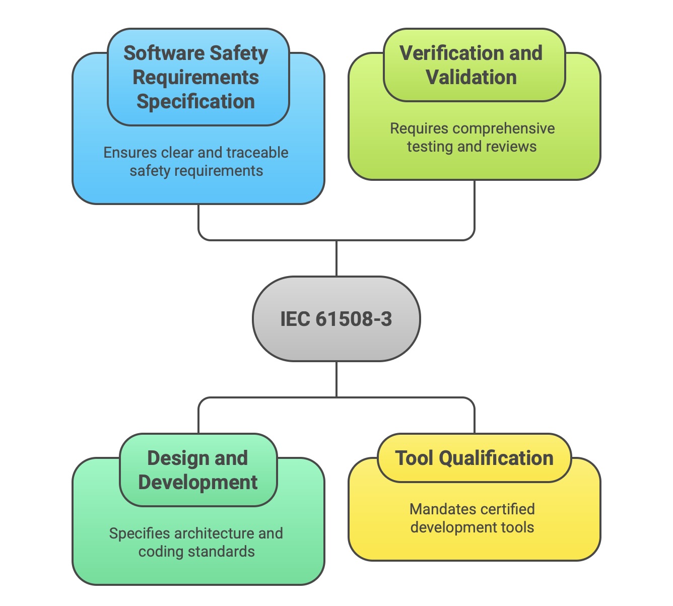
Software Safety Requirements Specification: Mandates a rigorous process for deriving and documenting software safety requirements, ensuring they are unambiguous, verifiable, and traceable to the overall system safety requirements.
Design and Development: Specifies requirements for software architecture, detailed design, and implementation. It recommends specific design principles and coding standards (such as MISRA C) to avoid common sources of programming errors.
Verification and Validation: Requires a comprehensive strategy for software verification at all stages (e.g., code reviews, static analysis) and validation testing (module, integration, and system testing) to confirm that the software correctly implements the safety requirements.
Tool Qualification: Mandates that software development tools (compilers, static analyzers, test tools) must themselves be qualified or certified to a level appropriate for the SIL of the software being developed, to ensure the tools do not introduce errors.
2.5 Parts 4-7: Definitions, Guidelines, and Methodologies
The final four parts of the standard provide the essential supporting information needed to apply the normative requirements effectively.
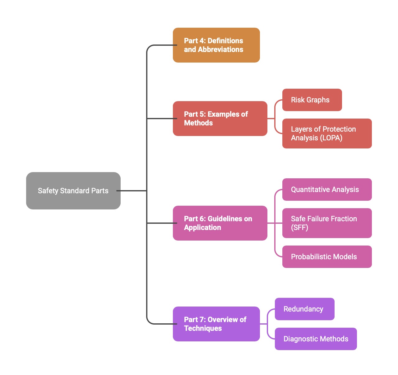
Part 4 (Definitions and abbreviations): This normative part acts as the dictionary for the standard, providing precise definitions for all key terms to ensure a common and unambiguous understanding.
Part 5 (Examples of methods for the determination of safety integrity levels): This informative part provides practical examples of how to perform a hazard and risk analysis to determine the required SIL for a safety function. It describes qualitative methods like risk graphs and semi-quantitative methods like Layers of Protection Analysis (LOPA).
Part 6 (Guidelines on the application of Parts 2 and 3): This informative part offers further guidance on meeting the hardware and software requirements. It is particularly useful for its detailed explanation of quantitative analysis, including the calculation of metrics like Safe Failure Fraction (SFF) and the application of probabilistic models.
Part 7 (Overview of techniques and measures): This informative part serves as a technical reference library. It provides detailed descriptions of the various engineering techniques, measures, and architectural designs (e.g., different forms of redundancy, diagnostic methods) that are referenced in the tables of Parts 2 and 3.
III. The Overall Safety Lifecycle: A Cradle-to-Grave Approach
The single most important mechanism for controlling systematic failures within the IEC 61508 framework is the Overall Safety Lifecycle. This structured, multi-phase model provides a comprehensive, “cradle-to-grave” roadmap for all activities related to a safety system, from its initial conception to its final decommissioning. The standard defines a nominal 16-phase lifecycle, which serves as a reference model that organizations can adapt to their specific projects and processes. The lifecycle is not merely a project management plan; its deliberate structure is designed to generate a complete, auditable chain of evidence that demonstrates compliance. Each phase has defined objectives, inputs, requirements, and outputs, where the verified output of one phase becomes the controlled input for the next, creating an unbroken and traceable link from the initial hazard analysis to the final operational system.
3.1 The 16-Phase Model: A Systematic Process for Ensuring Safety
The 16 phases of the safety lifecycle are logically grouped into three main stages: Analysis, Realisation, and Operation. This structure ensures that a system is thoroughly specified and understood before it is built, and that its safety is actively managed throughout its operational life. The entire process is a closed loop, recognizing that safety is a continuous activity, not a one-time achievement.
3.2 The Analysis Phases (1-5): From Concept to Requirements Allocation
The initial phases of the lifecycle are dedicated to analysis and specification. These phases are arguably the most critical, as any errors or omissions made here will propagate through the entire project, potentially leading to a system that is fundamentally unsafe, regardless of the quality of its subsequent design and implementation.
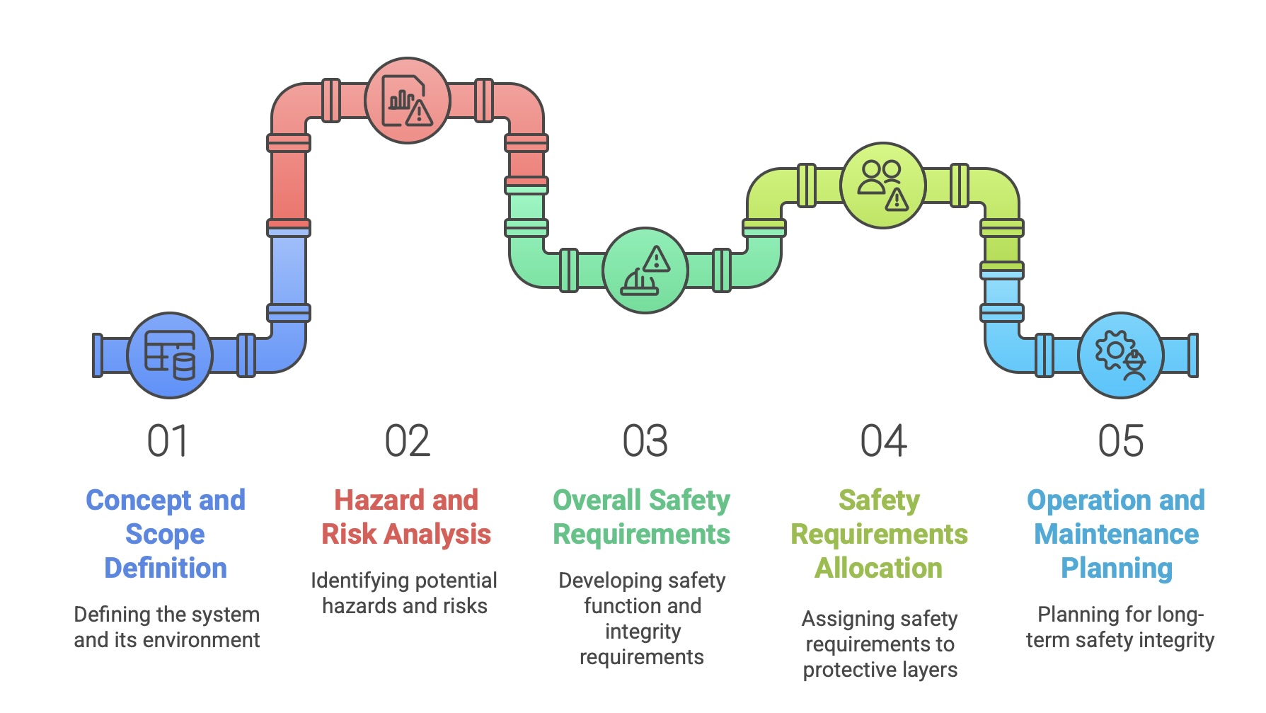
Phase 1: Concept and Scope Definition: The lifecycle begins with a clear definition of the system to be made safe, known as the Equipment Under Control (EUC), and its operational environment. This phase establishes the boundaries of the system and the scope of the subsequent hazard and risk analysis.
Phase 2: Hazard and Risk Analysis (HARA): This is a systematic investigation to identify all potential hazards, hazardous events, and the sequences of events that could lead to harm. This analysis must consider all reasonably foreseeable circumstances, including all modes of operation (e.g., startup, normal operation, maintenance, shutdown), fault conditions, and potential misuse. A variety of techniques, such as Hazard and Operability Studies (HAZOP), Failure Mode and Effects Analysis (FMEA), or Fault Tree Analysis (FTA), may be employed.
Phase 3: Overall Safety Requirements: Based on the HARA, this phase develops the specification for the overall safety requirements. This specification is twofold: it defines the safety function requirements (what the safety system must do to prevent or mitigate a hazard) and the safety integrity requirements (how reliably the system must perform that function). The integrity requirement is ultimately expressed as a Safety Integrity Level (SIL).
Phase 4: Safety Requirements Allocation: In this crucial step, the overall safety requirements are allocated to specific protective layers. The required safety functions and their associated SILs are assigned to designated E/E/PE safety-related systems, other technology safety-related systems (e.g., a mechanical relief valve), and/or external risk reduction facilities (e.g., a containment dike). This ensures that the responsibility for achieving the necessary risk reduction is clearly distributed among different technologies and systems.
Phase 5: Overall Operation and Maintenance Planning: Before design begins, an initial plan must be developed for the operation and maintenance of the safety systems. This forward-looking activity ensures that considerations for long-term safety integrity, such as proof testing intervals and repair procedures, are factored into the design from the outset.
3.3 The Realisation Phases (6-13): Design, Engineering, and Implementation
This central group of phases covers the entire process of designing, building, and validating the safety systems specified in the analysis phases.
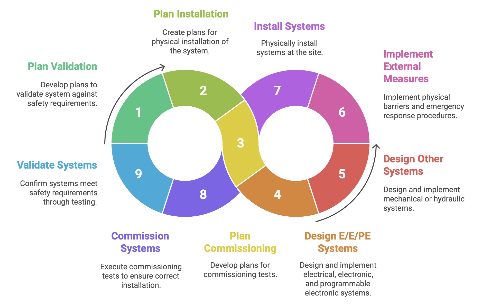
Phases 6, 7, and 8: Overall Planning (Validation, Installation, Commissioning): These are planning phases that run in parallel with the main design effort. They involve developing detailed plans for how the final system will be validated against the safety requirements (Phase 6), how it will be physically installed (Phase 7), and how it will be commissioned (Phase 8).
Phases 9, 10, and 11: Realisation of Safety-Related Systems: This is the core design and development work. It is executed in parallel for the different technologies identified in Phase 4.
Phase 9 (E/E/PE Systems): This phase encompasses the entire detailed design and implementation of the electrical, electronic, and programmable electronic safety systems. It is within this phase that the specific, detailed hardware (IEC 61508-2) and software (IEC 61508-3) safety lifecycles are executed.
Phase 10 (Other Technology Systems): This covers the realization of safety systems based on other technologies, such as mechanical or hydraulic systems.
Phase 11 (External Risk Reduction Facilities): This involves the implementation of external measures like physical barriers or emergency response procedures.
Phase 12: Overall Installation and Commissioning: Following the realization of the individual systems, this phase involves their physical installation at the site and the execution of commissioning tests to ensure they are installed correctly and are ready for validation.
Phase 13: Overall Safety Validation: This is a critical milestone. Validation is the process of confirming, through review and testing, that the fully integrated safety systems meet the overall safety requirements (both functional and integrity) that were specified back in Phase 3. It answers the question: “Did we build the right system?”
3.4 The Operation Phases (14-16): Maintenance, Modification, and Decommissioning
The final phases of the lifecycle address the long-term management of the safety system, recognizing that safety must be actively maintained throughout its operational life. Negligence in these phases can easily erode the safety integrity that was painstakingly built into the system.
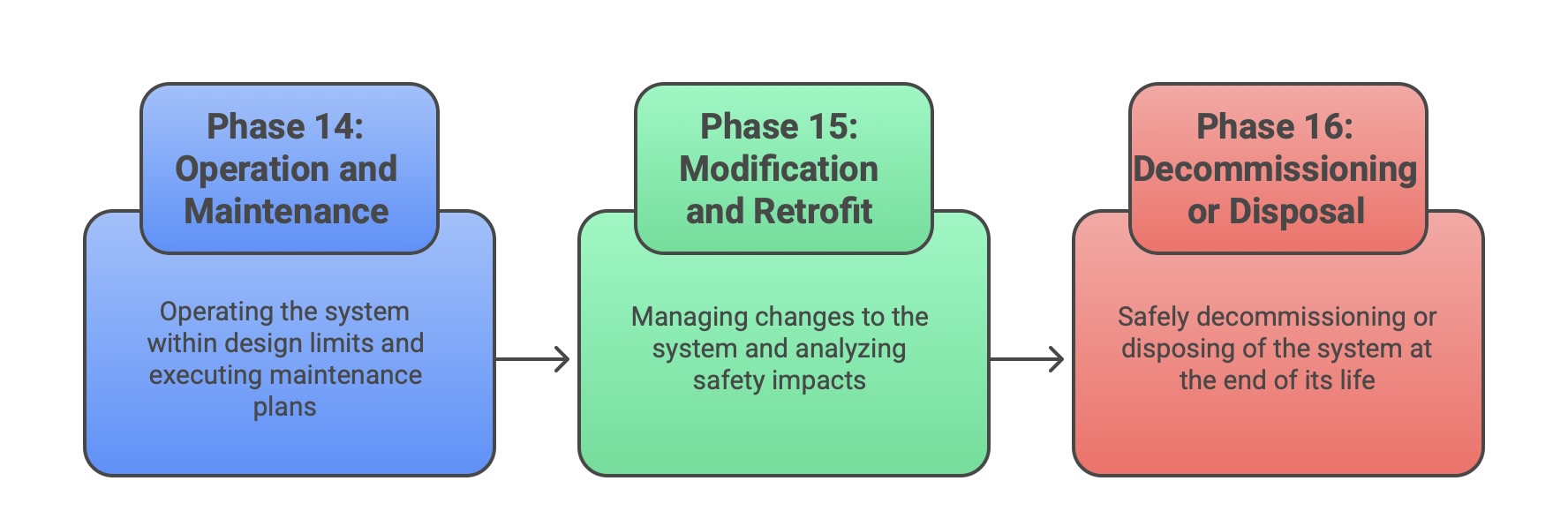
Phase 14: Overall Operation and Maintenance: This phase covers the entire operational life of the system. It involves operating the system within its design limits and executing the maintenance plan developed in Phase 5. This includes performing periodic proof tests to detect any unrevealed dangerous failures and carrying out repairs as needed to maintain the required functional safety.
Phase 15: Overall Modification and Retrofit: No system remains static. This phase mandates a formal management of change process. Any modification, no matter how small, must be carefully analyzed for its impact on safety. The lifecycle process must be re-entered at an appropriate phase to ensure that safety is not compromised either during the modification activity or by the final change.
Phase 16: Decommissioning or Disposal: At the end of its useful life, the safety system must be safely decommissioned or disposed of. This phase ensures that the process of taking the system out of service does not itself introduce new hazards.
IV. Quantifying Safety: Understanding Safety Integrity Levels (SILs)
While the safety lifecycle provides the procedural framework for IEC 61508, the concept of Safety Integrity Levels (SILs) provides its quantitative core. SILs are the mechanism by which the standard translates the abstract goal of “safety” into a specific, measurable, and verifiable engineering target. This transformation is pivotal, as it allows safety to be treated as a formal engineering requirement, subject to the same rigor of specification, design, and verification as any other system parameter like performance or efficiency.
4.1 Defining SILs: A Measure of Risk Reduction Performance
A Safety Integrity Level (SIL) is defined as a discrete level, one of four, used to specify the target level of risk reduction provided by a safety function. The standard specifies four levels, from SIL 1 to SIL 4, where SIL 1 represents the lowest level of safety integrity and SIL 4 represents the highest. Each successive level represents an order of magnitude increase in the required safety performance; that is, a SIL 3 function is required to be approximately ten times more reliable (less likely to fail dangerously) than a SIL 2 function.
It is a critical and often misunderstood point that a SIL is a property of a safety function, not of a product, component, or system in isolation. A component such as a pressure transmitter or a logic solver cannot be “SIL 3 certified” on its own. Instead, it can be certified as being suitable for use in a safety function up to a certain SIL. The SIL of the entire function depends on how that component is integrated with other components (sensors, logic solvers, final elements) and how the overall system is designed, operated, and maintained. The final SIL achieved is a characteristic of the complete end-to-end safety loop performing its specified action.
4.2 SIL Determination: Methodologies for Hazard and Risk Analysis (HARA)
The required SIL for a particular safety function is not chosen arbitrarily; it is determined through a systematic Hazard and Risk Analysis (HARA) process conducted during the early phases of the safety lifecycle. The fundamental procedure involves several steps:
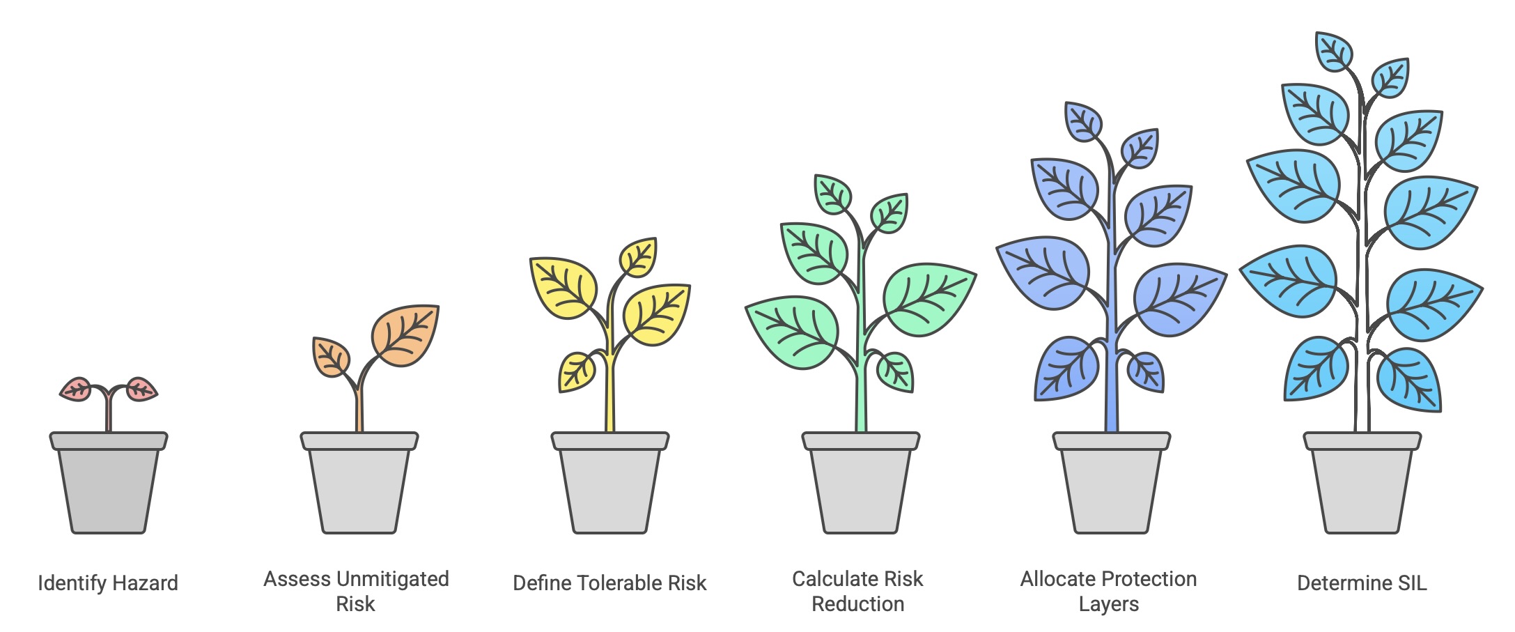
Identify the Hazard: A specific hazardous event associated with the Equipment Under Control (EUC) is identified (e.g., over-pressurization of a vessel).
Assess the Unmitigated Risk: The risk of this event occurring without the protection of the safety function is assessed. This risk is a function of the likelihood (frequency) of the event and the severity of its potential consequences (e.g., injury, environmental damage, financial loss).
Define the Tolerable Risk: The organization must define a target level of tolerable risk for that specific hazard, based on corporate standards, legal requirements, and societal values (the ALARP principle).
Calculate the Required Risk Reduction: The difference between the unmitigated risk and the tolerable risk determines the amount of risk reduction that must be provided by all protective layers combined.
Allocate to Protection Layers: This required risk reduction is allocated across various independent protection layers, which may include mechanical devices, alarms with operator intervention, and the Safety Instrumented System (SIS).
Determine the SIL: The risk reduction factor (RRF) demanded from the specific safety function within the SIS directly determines its required SIL.
IEC 61508 does not mandate a single method for performing this analysis, allowing for either qualitative or quantitative techniques. Part 5 of the standard provides informative examples of common methodologies:
Qualitative Methods (e.g., Risk Graph): These methods use calibrated parameters for consequence, frequency of exposure, and possibility of avoidance to map a scenario to a required SIL.
Semi-Quantitative Methods (e.g., Layers of Protection Analysis – LOPA): LOPA is a more detailed method that uses orders of magnitude to analyze the frequency of an initiating event and the probability of failure of each independent protection layer to determine the required performance of the final safety function.
4.3 Target Failure Measures: PFDavg and PFH Explained
The SIL provides a qualitative label (1, 2, 3, or 4), but to be useful for engineering design and verification, this label must be translated into a quantitative performance target. IEC 61508 defines two distinct target failure measures, the choice of which depends on the safety function’s mode of operation.
Low Demand Mode: This mode applies to safety functions that are called upon to act infrequently, defined as no more than once per year. A typical example is an emergency shutdown system in a chemical plant, which may never be required to operate during the plant’s lifetime. For these functions, the relevant metric is the Average Probability of Failure on Demand (). This value represents the average likelihood that the safety function will fail to perform its action when a demand occurs.
High Demand or Continuous Mode: This mode applies to functions that are required frequently (more than once per year) or that operate continuously to maintain a safe state. An example is a control system that continuously monitors and adjusts a machine’s speed to prevent it from entering a dangerous state. For these functions, the metric is the average frequency of a dangerous failure per hour (). This value represents the rate at which the function is expected to fail in a dangerous manner.
Each SIL is defined by a specific numerical range for these two metrics, establishing a clear, verifiable target for the system’s design. The following table summarizes these crucial relationships.
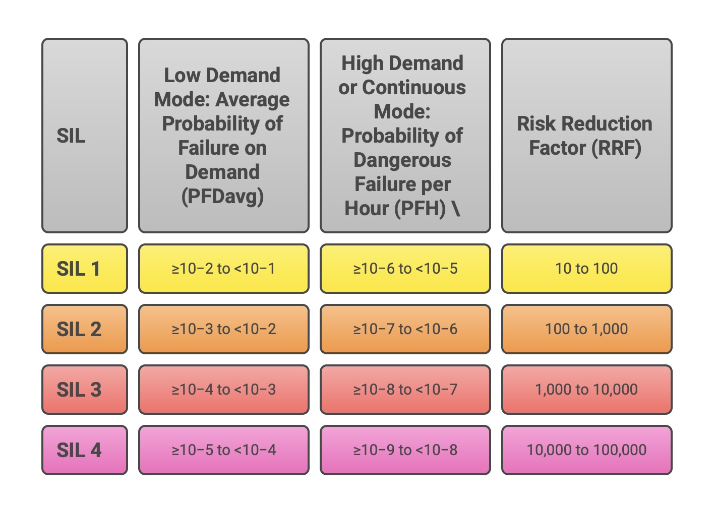
This table serves as the Rosetta Stone of functional safety, directly translating the required risk reduction from the HARA into a concrete probabilistic performance target that the engineering team must design to and verify against.
V. A Duality of Failure: Managing Systematic and Random Faults
To achieve the stringent probabilistic targets defined by the SILs, IEC 61508 mandates a dual-pronged strategy that addresses the two fundamental types of failures that can affect a safety system: systematic failures and random hardware failures. The standard recognizes that these two failure types have different origins and therefore require distinct and complementary control measures. A system’s claimed SIL is valid only if it demonstrates sufficient integrity against both types of failure. This holistic approach is enforced through what can be described as a “triple-lock” on safety: a system must satisfy stringent requirements for process quality (Systematic Capability), architectural robustness (Architectural Constraints), and probabilistic performance (PFD/PFH calculation). Failure to meet any one of these three independent requirements invalidates the SIL claim, preventing designers from compensating for a poor design process with excessive hardware redundancy, or vice versa.
5.1 Systematic Failures: Controlling Errors in Process and Design
Systematic failures are failures that are deterministically linked to a specific cause, which can only be eliminated by modifying the design, manufacturing process, operational procedures, or documentation. These failures are inherent in the system from the moment it is created. Common examples include software bugs, errors in the safety requirements specification, incorrect component selection, or flaws in maintenance procedures. Because they are not random, their occurrence cannot be predicted by probabilistic models of hardware reliability.
The primary defense against systematic failures is a rigorous, structured process. IEC 61508 addresses this by mandating strict adherence to the safety lifecycle. Every phase of the lifecycle, with its requirements for planning, documentation, verification, and validation, is designed to prevent the introduction of errors and to detect and correct any that are introduced.
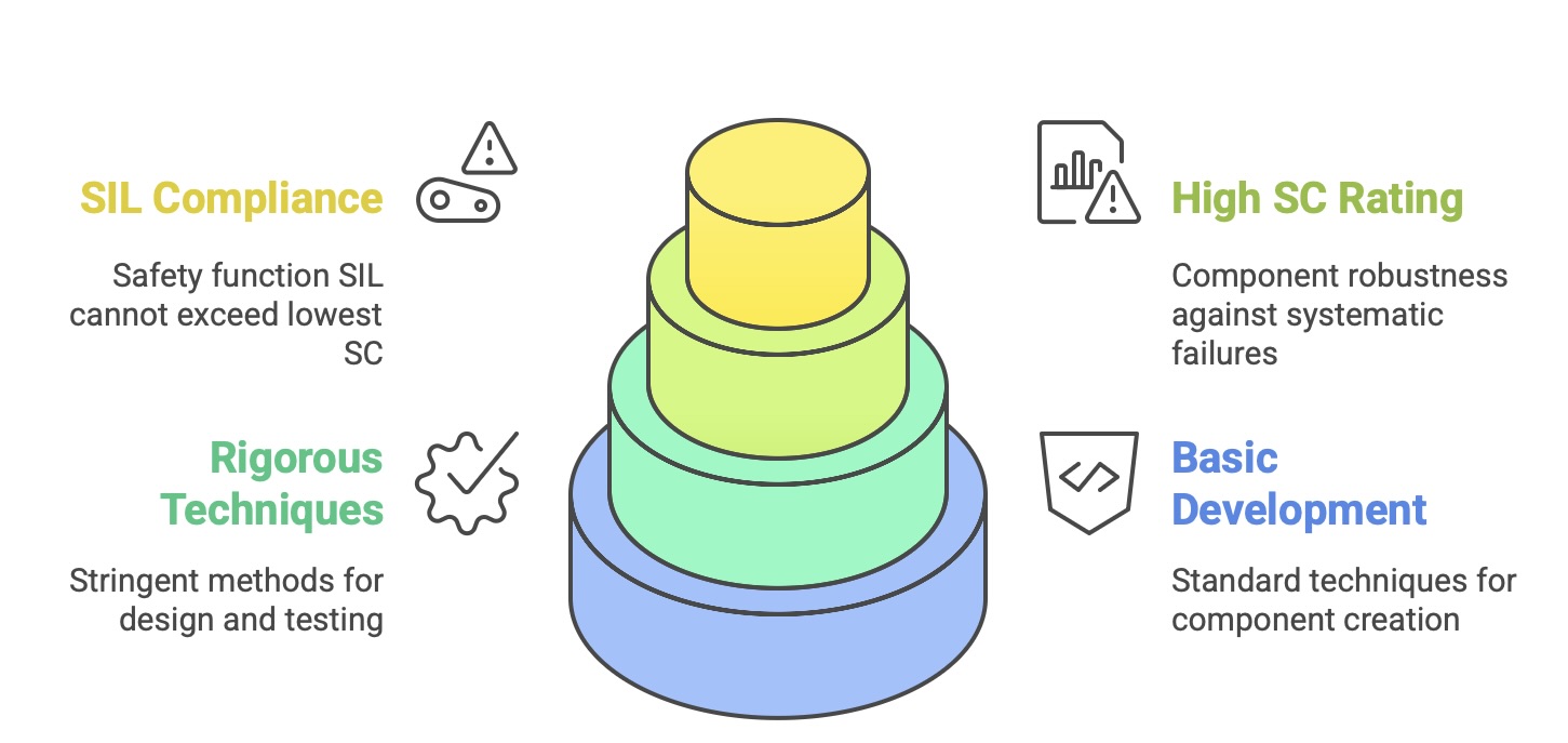
The measure of a component’s or system’s inherent robustness against systematic failures is its Systematic Capability (SC). A component is assigned an SC rating (e.g., SC 2, SC 3) based on the rigor of the development process used to create it. For example, to achieve a higher SC for a software component, Part 3 of the standard requires more stringent techniques for design, coding, and testing. A fundamental rule of the standard is that the SIL of a safety function can be no higher than the lowest SC of any component or subsystem used to implement that function. This means that a SIL 3 safety function cannot be built using a component that was only developed with a process sufficient for SC 2, no matter how reliable its hardware is predicted to be. This rule firmly locks in the requirement for process quality.
5.2 Random Hardware Failures: A Probabilistic Approach
In contrast to systematic failures, random hardware failures occur at unpredictable times during the operational life of a device as a result of physical degradation mechanisms (e.g., wear-out, material defects, environmental stress). These failures cannot be eliminated from any physical component, but their likelihood can be estimated, and their effects can be managed. IEC 61508 provides two primary mechanisms for controlling the risk posed by random hardware failures:
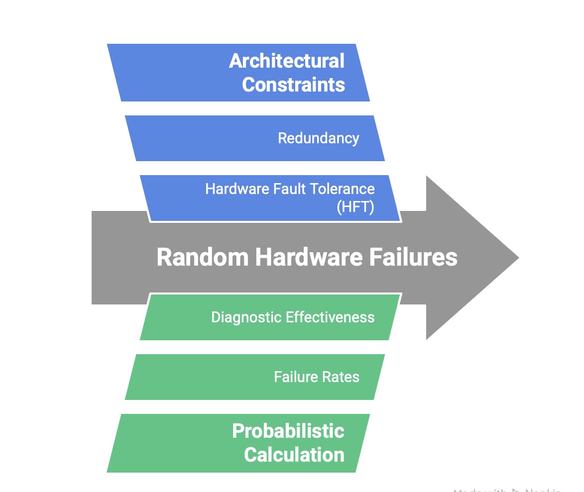
Architectural Constraints: These are prescriptive rules that mandate a minimum level of fault tolerance and architectural robustness based on the target SIL. The primary metric for this is Hardware Fault Tolerance (HFT), which is the ability of a subsystem to continue performing its required function in the presence of one or more hardware faults. For example, an HFT of 1 means the subsystem can tolerate a single fault (e.g., through redundancy) and still operate correctly. Part 2 of the standard specifies the minimum HFT required for a given SIL, depending on the complexity and failure characteristics of the components used. These constraints prevent designers from claiming a high SIL for a simple, non-redundant architecture, even if theoretical calculations suggest a very low failure rate. This provides a fundamental defense against uncertainties in failure rate data and modeling. The standard offers two methods, Route 1h and Route 2h, to demonstrate sufficient architectural integrity.
Probabilistic Calculation: This is the quantitative verification that the overall design meets the target failure measure ( or ) for its assigned SIL. This calculation involves creating a reliability model of the entire safety function, from sensor to final element. It requires key data points such as the failure rates of each component, the effectiveness of any diagnostic tests in detecting failures, the frequency of proof tests, and the mean time to repair detected failures. This calculation provides the ultimate quantitative proof that the system’s performance meets the required level of risk reduction.
5.3 Key Metrics: SFF, DC, and HFT
The quantitative analysis of random hardware failures relies on several key parameters that characterize the safety performance of a component or subsystem. Understanding these metrics is essential for applying the requirements of IEC 61508-2.
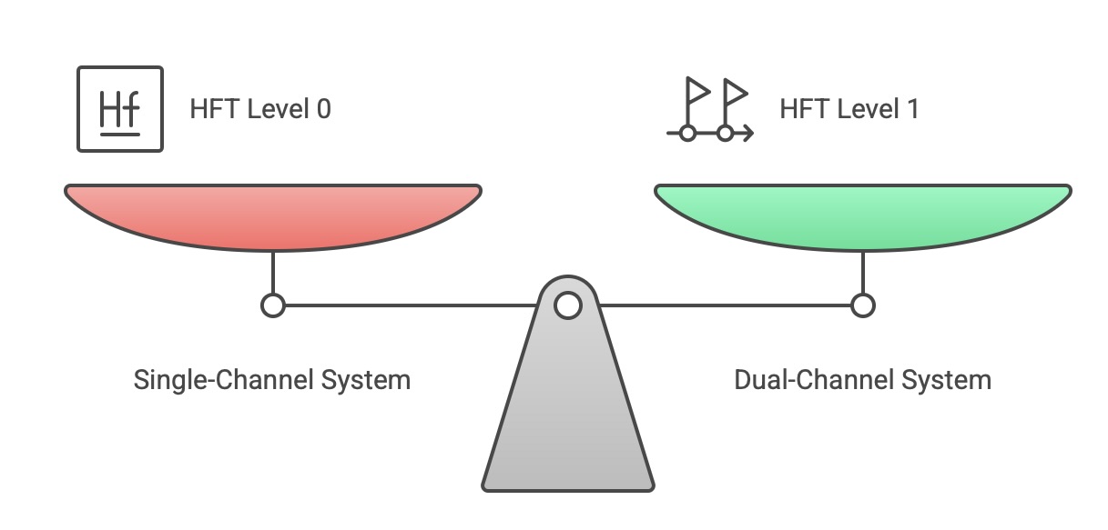
Hardware Fault Tolerance (HFT): As previously mentioned, HFT is a property of the architecture. An HFT of N means that N+1 faults are required to cause a loss of the safety function. For example, a simple single-channel system has an HFT of 0. A dual-channel system where either channel can perform the function has an HFT of 1.
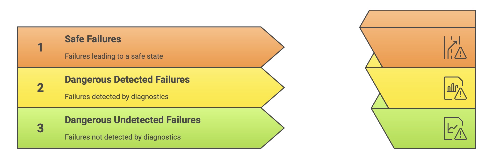
Safe Failure Fraction (SFF): This metric describes the proportion of a component’s failures that are “safe.” A failure is considered safe if it either leads to the system entering a safe state directly (a “safe failure”) or if it is a dangerous failure that is detected by automated online diagnostic tests (a “dangerous detected failure”). The SFF is calculated as:
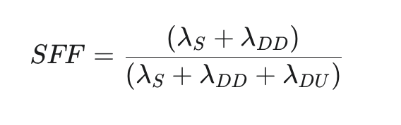
where is the rate of safe failures, is the rate of dangerous detected failures, and is the rate of dangerous undetected failures. A high SFF indicates that the component is either inherently fail-safe or has excellent self-diagnostic capabilities. The required SFF is linked to the target SIL and the HFT of the architecture.
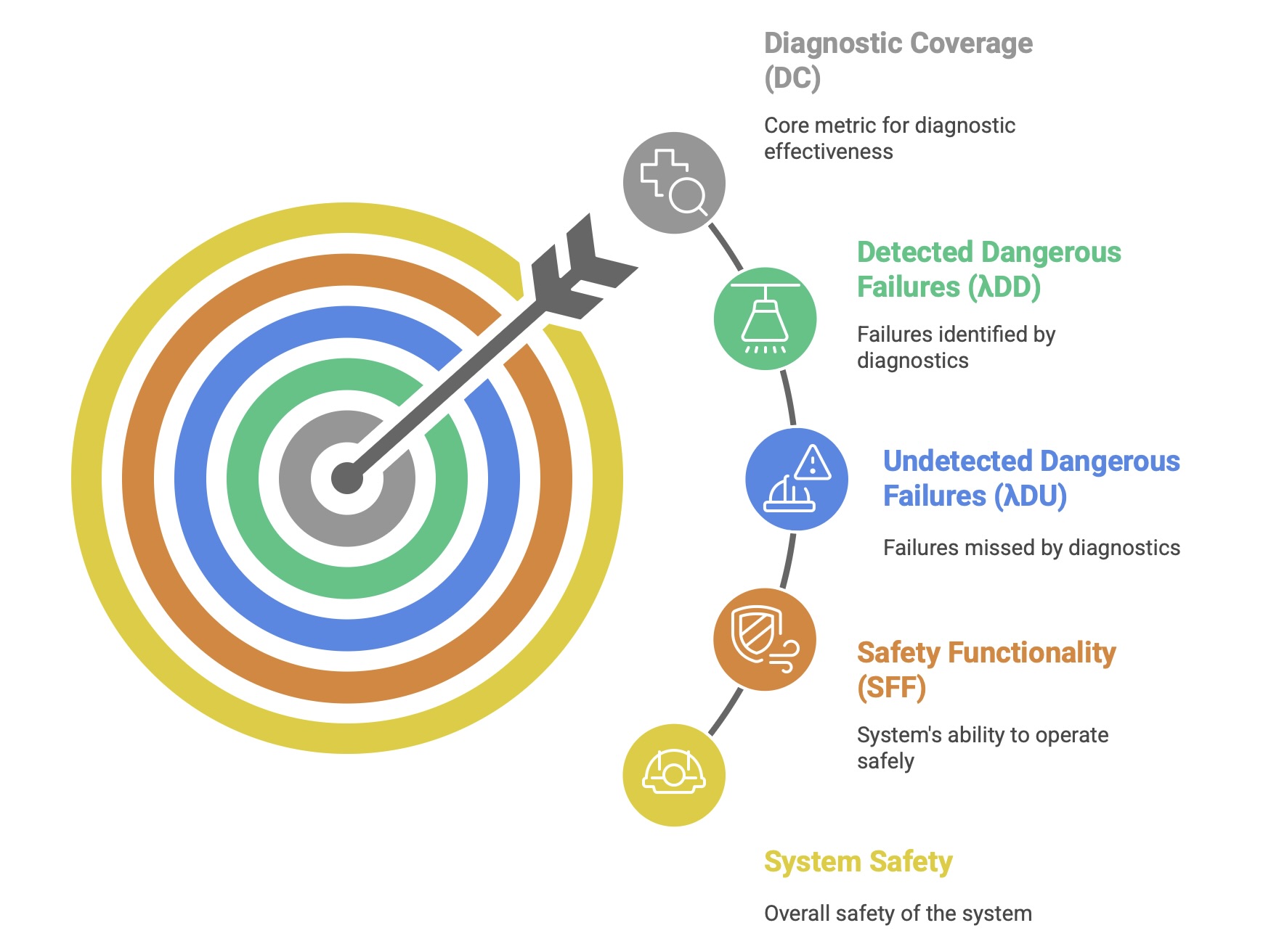
Diagnostic Coverage (DC): This metric measures the effectiveness of the automatic diagnostic tests implemented within a component or subsystem. It is defined as the fraction of dangerous failures that are detected by these diagnostics. It is calculated as:
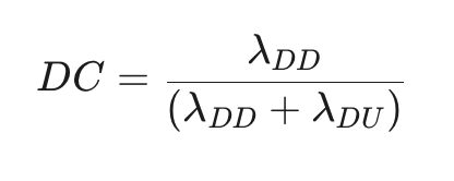
A high DC is crucial for achieving a high SFF and for allowing the system to respond safely to internal faults. The standard provides guidance on the DC values that can be claimed for various diagnostic techniques.
Together, these metrics and the architectural constraints form the basis of the hardware safety integrity analysis, providing the evidence needed to demonstrate that the system is sufficiently robust against the inevitable random failures of its components.
VI. The IEC 61508 Ecosystem: Relationship with Sector-Specific Standards
While IEC 61508 provides a robust and comprehensive framework, its generic, all-encompassing nature makes it a complex document to apply directly to a specific industrial context. Recognizing this, one of the standard’s primary objectives was to serve as a foundation, or “umbrella,” upon which more focused, sector-specific standards could be built. As technology and system complexity increased across various industries, it became apparent that a one-size-fits-all approach was insufficient to address the unique challenges, operational environments, and risk profiles of different sectors. This has led to the development of a family of functional safety standards, each adapting the core principles of IEC 61508 to a specific domain.
This ecosystem of standards, while promoting consistency at a high level, also creates a complex compliance landscape. A manufacturer of a general-purpose component, such as a microcontroller or a pressure sensor, may find their product being used in automotive, industrial, and machinery applications. This requires the manufacturer to possess deep expertise across multiple standards, as the interpretation of fundamental concepts, terminology, and requirements can differ in subtle but critical ways between domains. The safety documentation and failure rate data provided for such a component must be presented in a way that is usable and compliant for engineers working under the rules of ISO 26262, IEC 61511, and IEC 62061 simultaneously.
6.1 Adapting the Framework: The Need for Industry-Specific Standards
Sector-specific standards serve several key purposes. They translate the abstract terminology of IEC 61508 into the familiar language of a particular industry, making the standard more accessible and easier to interpret for practitioners in that field. They also allow for the inclusion of requirements and guidance tailored to the specific types of hazards, equipment, and operational practices common to that sector. For example, the considerations for a safety system in a mass-produced automobile are vastly different from those for a bespoke chemical processing plant. The derivative standards address these differences while maintaining alignment with the core lifecycle and integrity concepts of the parent standard.
6.2 Comparative Analysis: IEC 61508 vs. ISO 26262 (Automotive)
ISO 26262, “Road vehicles – Functional safety,” is the adaptation of IEC 61508 for electrical and electronic (E/E) systems in production passenger cars. It has become the definitive standard for the automotive industry. While it shares the same foundational risk-based approach and lifecycle concepts, it introduces several key differences to suit the automotive context:
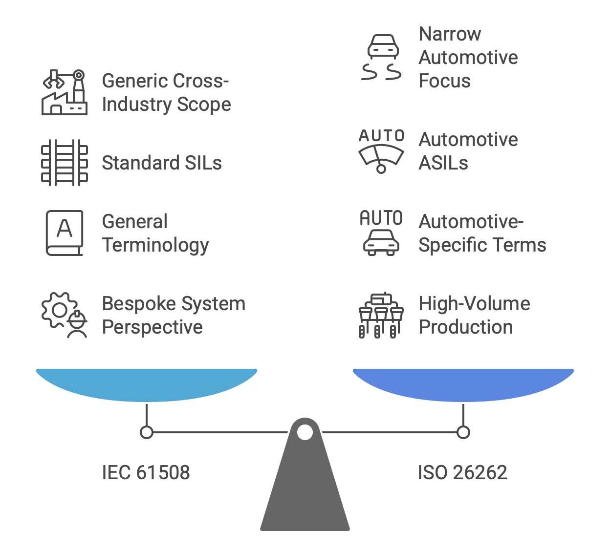
Scope and Focus: ISO 26262 is narrowly focused on road vehicles, whereas IEC 61508 is a generic, cross-industry standard.
Safety Integrity Levels: ISO 26262 replaces SILs with Automotive Safety Integrity Levels (ASILs). There are four ASILs, from ASIL A (lowest integrity) to ASIL D (highest integrity). The determination of the required ASIL is based on an analysis of three factors: Severity, Exposure, and Controllability by the driver. The “Controllability” factor is unique to the automotive context.
Terminology and Concepts: The standard introduces automotive-specific terminology. For instance, the high-level safety objective is a “Safety Goal” rather than a “Safety Function”. The concept of “Hardware Fault Tolerance” (HFT) from IEC 61508 is not explicitly used, leading to different approaches for demonstrating hardware architectural integrity.
Production Context: ISO 26262 is tailored for a high-volume production environment, whereas IEC 61508 was written more from the perspective of a bespoke, one-off system. This influences aspects like the use of field data (“proven in use”) and requirements for distributed development across a complex supply chain.
6.3 Comparative Analysis: IEC 61508 vs. IEC 61511 (Process Industry)
IEC 61511, “Functional safety – Safety instrumented systems for the process industry sector,” is the key standard for industries such as chemical manufacturing, oil and gas, and pharmaceuticals. The most significant distinction between IEC 61508 and IEC 61511 lies in their target audience and role within the supply chain:
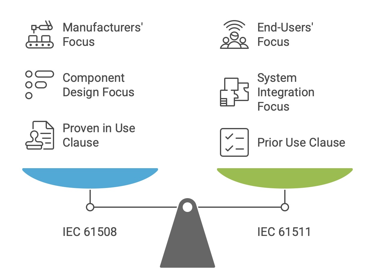
Target User: IEC 61508 is primarily aimed at the manufacturers of safety components and subsystems (e.g., sensors, logic solvers, valves). It provides the requirements for developing a product that is suitable for use in safety applications. In contrast, IEC 61511 is aimed at the end-users, system integrators, and engineering contractorswho design, build, and operate the overall Safety Instrumented System (SIS) using components from various manufacturers.
Focus: IEC 61508 contains detailed requirements for embedded software and the internal design of complex electronic hardware. IEC 61511 focuses more on the integration of pre-existing components into a complete safety function and on the application-level programming of the logic solver, typically using Limited Variability Languages (LVL) rather than Full Variability Languages (FVL) like C or C++.
Component Justification: While IEC 61508 provides a “Proven in Use” clause for justifying the use of components based on extensive, high-quality historical operating data from the manufacturer, IEC 61511 offers a “Prior Use” clause. “Prior Use” allows an end-user to justify using a component based on their own successful operating experience with it in a similar application and environment, even if the component does not have a full IEC 61508 compliance certificate.
6.4 Comparative Analysis: IEC 61508 vs. IEC 62061 (Machinery)
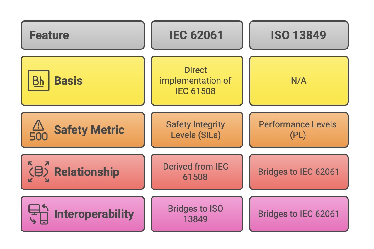
IEC 62061, “Safety of machinery – Functional safety of safety-related control systems,” is the machinery sector’s direct implementation of IEC 61508. It provides a methodology for the design and validation of safety-related electrical, electronic, and programmable electronic control systems used on machinery. A key feature of the machinery safety landscape is the co-existence of IEC 62061 with another major standard, ISO 13849, which uses a different metric called Performance Levels (PL).
Relationship to IEC 61508: IEC 62061 is explicitly derived from IEC 61508 and uses the same core concepts, including the safety lifecycle and SILs as the measure of safety integrity. Its approach to hardware architecture remains closely linked to the Route 1h methodology described in IEC 61508-2.
Bridging to ISO 13849: A significant role of the latest edition of IEC 62061 is to provide a bridge to the widely used ISO 13849 standard. It allows for a more seamless integration of subsystems designed according to the Performance Level (PL) methodology of ISO 13849 into an overall safety function whose integrity is specified by a SIL. This interoperability is crucial for machine builders who may use components and subsystems designed to both standards.
The following table provides a high-level comparison of these key standards.
VII. From Theory to Practice: Implementation, Compliance, and Certification
Translating the dense requirements of IEC 61508 from theory into practice is a significant undertaking that requires organizational commitment, technical expertise, and a systematic approach. It is not merely a technical exercise for the engineering department but a strategic initiative that involves management, quality assurance, and operational personnel. Successful implementation hinges on establishing a robust management system, ensuring personnel are competent, navigating common challenges, and following a structured path toward compliance and, if desired, certification.
7.1 Establishing a Functional Safety Management System (FSMS)
The standard explicitly mandates the establishment of a Functional Safety Management System (FSMS) that must be in place throughout the entire safety lifecycle. The FSMS is the organizational and procedural framework that ensures functional safety activities are planned, controlled, and executed in a consistent and verifiable manner. It is the backbone of compliance and the primary defense against systematic failures arising from organizational or procedural deficiencies.
An effective FSMS, as required by the standard, must address several key areas:
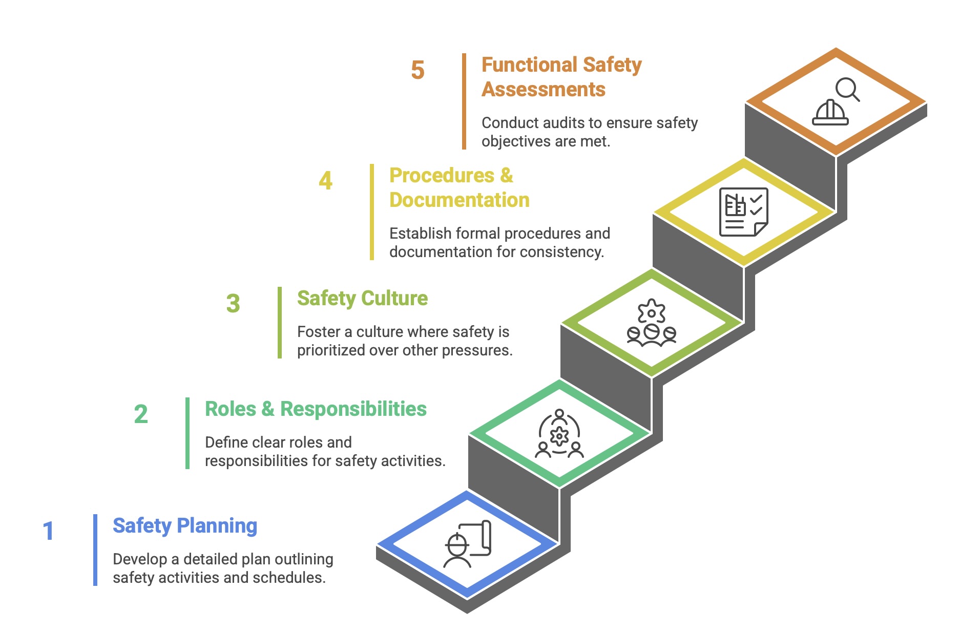
Safety Planning: A detailed safety plan must be created for each project, outlining all the safety lifecycle activities to be performed, the schedule for these activities, and the personnel responsible for them.
Roles and Responsibilities: The FSMS must clearly define the roles, responsibilities, and authority of all persons and departments involved in safety lifecycle activities.
Safety Culture: The organization must demonstrate and foster a positive safety culture, where safety takes precedence over commercial or schedule pressures.
Procedures and Documentation: The system must include formal procedures for all lifecycle activities, including configuration management, change control, and documentation. Pro-forma documents and templates should be developed to ensure consistency.
Functional Safety Assessments (FSA): The FSMS must specify a schedule of FSAs. These are formal audits, conducted by independent individuals or teams, to review the execution of lifecycle phases and judge whether the functional safety objectives have been achieved.
7.2 The Critical Role of Personnel Competency
IEC 61508 places strong emphasis on the competency of the individuals and teams responsible for safety lifecycle activities. The standard recognizes that even the most rigorous process will fail if executed by personnel who lack the necessary skills, training, and experience.
Managing competency is a formal requirement of the FSMS. Organizations must:
Identify the competencies required for each role involved in the safety lifecycle.
Ensure that individuals assigned to these roles possess the appropriate education, training, experience, and knowledge of the specific standards.
Maintain records of personnel competency.
Conduct periodic assessments of competence to ensure skills remain current.
This requirement extends to all levels, including managers and leaders, who must have adequate knowledge to be accountable for the safety-related activities they oversee.
7.3 Common Implementation Challenges and Mitigation Strategies
Organizations often face significant challenges when first implementing IEC 61508. The generic nature of the standard can make its requirements difficult to interpret and apply to a specific context. Common pitfalls and challenges include:
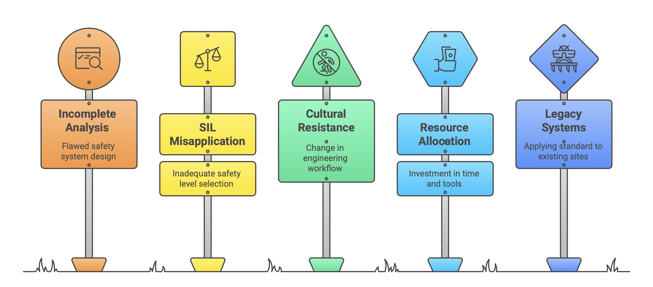
Incomplete Hazard Analysis: A failure to correctly identify all hazards or misunderstanding the process hazards a safety system is meant to control can lead to a fundamentally flawed design.
Misapplication of SIL Determination: Using generic “rules of thumb” or inappropriate risk assessment methods can lead to either “SIL inflation” (over-engineering and unnecessary cost) or, more dangerously, the selection of an inadequate SIL.
Cultural Resistance: Implementing the rigorous processes and documentation requirements of IEC 61508 often requires a significant change in how engineering teams work, which can be met with resistance.
Resource Allocation: Achieving compliance requires a substantial investment in training, tools, and personnel time, which may be difficult to secure without strong management commitment.
Legacy Systems: Applying the standard to existing “brownfield” sites or legacy systems that were not developed according to the lifecycle presents a major challenge.
The consequences of failing to overcome these challenges can be severe, ranging from legal liabilities and financial penalties to catastrophic accidents, such as the 2005 Texas City refinery explosion, which was attributed to safety violations and poorly maintained equipment. Mitigation strategies include investing in comprehensive training, adopting a phased implementation approach, securing strong management buy-in, and leveraging the expertise of external consultants where necessary.
7.4 Best Practices and the Path to Certification
While challenging, achieving compliance is manageable through the adoption of established best practices. A practical roadmap for an organization often involves the following steps:
 x§
x§
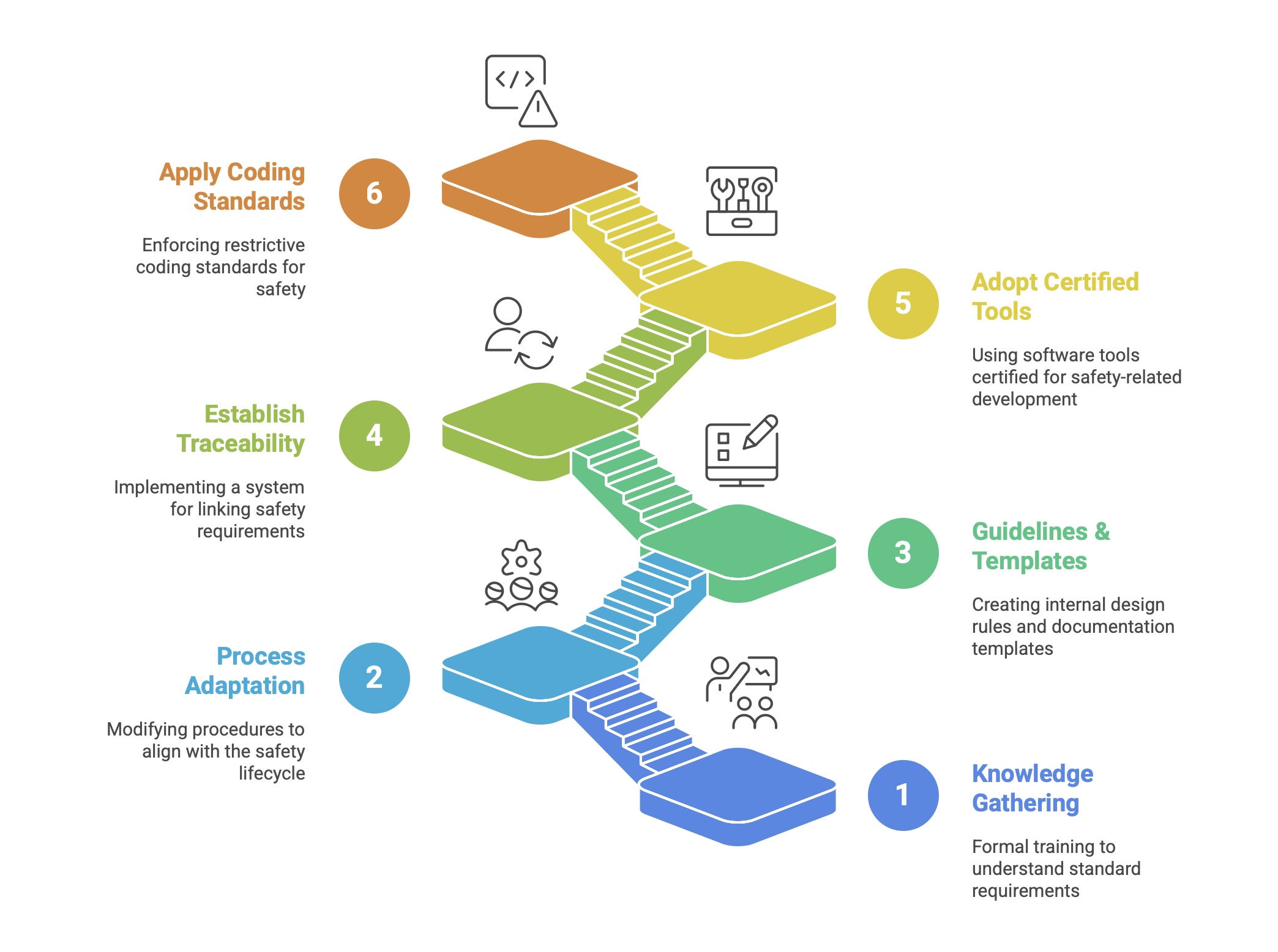
Knowledge Gathering: Begin with formal training to ensure all stakeholders have a solid understanding of the standard’s requirements.
Process Adaptation: Modify existing company engineering procedures, work instructions, and quality management systems to align with the safety lifecycle model.
Develop Guidelines and Templates: Create internal design guidelines that translate the standard’s generic requirements into practical, company-specific rules. Develop standardized templates for all required documentation (e.g., Safety Requirements Specification).
Establish Traceability: Implement a robust system for requirements traceability, linking safety requirements through design, implementation, and testing. Using a dedicated requirements management tool is highly recommended.
Adopt Certified Tools: Use software tools (e.g., compilers, static analyzers, unit test tools) that have been certified by an accredited body (like TÜV or exida) for use in safety-related development. This simplifies the tool qualification process required by the standard.
Apply Coding Standards: Enforce the use of a restrictive coding standard, such as MISRA C/C++, to prevent common programming errors in safety-critical software.
Certification is the formal process by which an independent, accredited third-party body validates that a product, process, or system complies with the requirements of IEC 61508. While the standard itself does not mandate third-party certification, it is often a market or customer requirement and provides a high degree of confidence in the product’s safety integrity. The certification process is a rigorous audit that typically involves:
Concept Inspection: An early review of the product’s specifications and safety concept.
Main Inspection: A detailed analysis of the entire development process, including the FSMS, design documentation, hardware failure analyses (e.g., FMEA, FMEDA), software static analysis, and verification/validation test results.
Final Certification: If all requirements are met, a certificate is issued that specifies the scope of compliance, including the achieved SIL capability and any constraints on use.
VIII. The Horizon of Safety: Future Trends and the Evolution of IEC 61508
The field of functional safety is not static. It exists in a dynamic relationship with technological advancement, where new innovations introduce both novel safety challenges and powerful new tools for managing risk. As industries move toward greater connectivity, autonomy, and intelligence, the principles codified in IEC 61508 must evolve to remain relevant. The future of the standard and the discipline it governs will be shaped by the integration of cybersecurity, the challenge of artificial intelligence, and the transformative impact of Industry 4.0. This evolution represents a fundamental shift in focus—from assuring safety in systems that are merely complicated to assuring safety in systems that are complex and adaptive. The current standard, built on a foundation of deterministic and fully verifiable design, excels at managing complicated systems. However, emerging technologies introduce non-determinism, dynamic reconfiguration, and intelligent adversaries, which are hallmarks of complex adaptive systems. The future of IEC 61508 will depend on its ability to incorporate new frameworks for managing this uncertainty and adaptation.
8.1 The Convergence of Safety and Security: Integrating IEC 62443
Perhaps the most immediate and critical trend is the convergence of functional safety and cybersecurity. The traditional model of a safety system was often one of physical isolation. However, the rise of Industry 4.0 and the Industrial Internet of Things (IIoT) means that safety-critical systems are now frequently connected to plant-wide or even external networks. This connectivity creates a new attack vector: a malicious cyber-attack could intentionally compromise or disable a safety function, with the same catastrophic consequences as a random hardware failure.
This reality has made it clear that safety can no longer be assured without also assuring security. The second edition of IEC 61508 acknowledges this link by requiring a security risk assessment to be performed, but it does so in an informative annex and directs users to the IEC 62443 series of standards for detailed guidance on industrial cybersecurity. The clear industry trajectory is toward a tighter integration of the safety lifecycle (IEC 61508) and the security lifecycle (IEC 62443). Future safety assessments will increasingly require evidence that cybersecurity threats have been identified and mitigated as part of the overall demonstration of safety, leading to a demand for products and systems with dual certification for both standards.
8.2 The Challenge of Artificial Intelligence and Machine Learning in Safety Systems
Artificial Intelligence (AI) and Machine Learning (ML) present a profound challenge to the foundational principles of functional safety. Standards like IEC 61511 have historically forbidden the use of AI in safety functions. The reason for this prohibition is fundamental: the decision-making process of many AI systems, particularly deep neural networks, is not transparent, easily understandable, or systematically verifiable using the methods prescribed by IEC 61508. The standard is built upon the ability to trace every requirement to a specific, deterministic implementation and to verify that implementation exhaustively. The non-deterministic and “black box” nature of AI makes this traceability and verification exceptionally difficult, if not impossible.
Despite this, AI is becoming essential for safety-critical applications, most notably in the perception systems of autonomous vehicles, which use ML to detect pedestrians and obstacles. The functional safety community is actively working to bridge this gap. A key development is the technical report ISO/IEC TR 5469, “Artificial Intelligence – Functional Safety and AI Systems,” which represents an initial step toward creating a framework and common vocabulary for certifying AI-based safety systems. The future evolution of IEC 61508 will need to develop new approaches to validation and verification that can provide the necessary confidence in AI-driven safety functions, likely focusing on black-box testing, fault injection, and extensive simulation rather than traditional code-level analysis.
8.3 Implications of Industry 4.0, IoT, and Digital Twins
The broader trend of Industry 4.0, characterized by hyper-connectivity, data analytics, and cyber-physical systems, is reshaping the environment in which safety systems operate. This brings new risks, particularly related to security and complexity, but also offers powerful new opportunities for enhancing safety. Future concepts in functional safety that are being actively explored include:
Digital Twins for Safety Validation: Using a high-fidelity digital model of a plant or machine to simulate hazardous scenarios and validate the response of the safety system in a safe, virtual environment. This allows for far more extensive testing than is possible on the physical asset.
Cloud-Based Analytics and Maintenance: Leveraging cloud platforms to collect and analyze diagnostic data from safety systems across an enterprise. This can enable predictive maintenance to prevent failures and can streamline the management and documentation of proof tests and compliance audits.
Decentralized Safety Logic: Moving away from monolithic central safety PLCs to a more distributed architecture where “edge” controllers run safety logic locally. This can improve response times and increase the resilience of the overall system.
8.4 Looking Ahead: The Development of IEC 61508 Edition 3
The IEC is currently in the process of developing the third edition of IEC 61508 to address the evolving technological landscape. While the final content is still under development, some key details about the timeline are public:
Status: A Committee Draft (CD) has been published and has undergone a commenting phase by national standards bodies.
Expected Publication: The consensus points to a publication date for the complete Edition 3 sometime in 2027. Forecasts for specific parts, such as Part 3 (Software), suggest a possible release in 2026, with a proposed stability date for the new edition extending to 2028.
While specific technical changes are not yet finalized, the overarching goal will be to maintain the established rigor of the standard’s performance levels while increasing its flexibility to accommodate new technologies and application areas, such as defense and aerospace. It is widely expected that Edition 3 will feature more explicit and integrated requirements for cybersecurity, reflecting its critical importance to functional safety. The standard will also likely begin to lay the groundwork for addressing the challenges posed by AI and autonomous systems, setting the stage for the future of safety engineering.
IX. Conclusion: The Enduring Significance of IEC 61508
IEC 61508 stands as more than just a technical standard; it represents a comprehensive and disciplined engineering philosophy for managing risk in an era of increasing technological complexity. Its introduction marked a pivotal transition from reactive, incident-driven safety practices to a proactive, systematic, and evidence-based framework that spans the entire lifecycle of a safety-related system. By establishing a common language, a risk-based methodology (ALARP), and quantifiable performance targets (SILs), the standard has successfully transformed the abstract concept of safety into a tangible and manageable engineering discipline.
The dual-pillar approach of the standard—addressing systematic failures through the rigor of the safety lifecycle and random hardware failures through probabilistic analysis and architectural constraints—provides a holistic and robust strategy for achieving safety integrity. This framework has proven so effective that it has become the bedrock of functional safety across a vast array of critical industries, from automotive and process control to machinery and railways, spawning a harmonized ecosystem of sector-specific standards.
However, the technological landscape is in constant flux. The accelerating convergence of operational technology (OT) and information technology (IT), the rise of non-deterministic artificial intelligence, and the proliferation of interconnected devices under the banner of Industry 4.0 present profound challenges to the established paradigms of safety verification and validation. The future relevance of IEC 61508 will depend on its ability to evolve and adapt to these new realities. The ongoing work on Edition 3, coupled with emerging guidance on cybersecurity and AI, indicates that the standard is poised to meet these challenges.
Ultimately, the enduring significance of IEC 61508 lies in its process-driven core. It instills the discipline of asking not just “Is the system safe?” but “Can we prove, with auditable evidence, that we have followed a rigorous process to make the system acceptably safe?” In a world where the consequences of failure are measured in lives, environmental impact, and economic devastation, this structured approach to achieving and demonstrating safety remains an indispensable tool for modern engineering.