
The Definitive Guide to ANSI/ISA-5.1: A Comprehensive Analysis of Instrumentation and Control Symbology
Part 1: The Foundation of a Universal Language in Automation
1.1 The International Society of Automation (ISA) and the Genesis of a Standard
In the landscape of modern industrial automation, clarity and precision in communication are not merely conveniences; they are foundational pillars of safety, efficiency, and operational excellence. The language used to describe and document complex measurement and control systems must be universal, unambiguous, and understood by a diverse range of professionals. At the heart of this universal language lies the ANSI/ISA-5.1 standard, a comprehensive system of symbols and identifiers. To fully appreciate the standard’s significance, one must first understand the organization behind it: the International Society of Automation (ISA).
Founded on April 28, 1945, as the Instrument Society of America, the ISA emerged from a collective need recognized by 18 local instrument societies in the United States. The Second World War had catalyzed the widespread use of industrial instruments, and leaders in the field saw an urgent need for a national organization to facilitate the sharing of information and to establish uniformity and standards. Today, the ISA is a global, non-profit professional association that sets the standard for professionals who apply engineering and technology to manage, secure, and improve modern automation and control systems across critical infrastructure and industry.
The ISA’s standards development process is a cornerstone of its mission. It is a consensus-based model, accredited by the American National Standards Institute (ANSI), which ensures that the development process is open, balanced, and free from dominance by any single interest, company, or organization. This rigorous process involves the voluntary participation of over 3,000 experts from more than 40 countries, who contribute their collective knowledge to create and maintain over 150 standards, recommended practices, and technical reports. These are not government regulations but voluntary documents that represent industry best practices, often referenced in contracts and, in some cases, regulations.
The history of the ISA-5.1 standard is inextricably linked to the history of the ISA itself. Demonstrating the foundational importance of this work, the very first standard published by the society in 1949 was RP 5.1 Instrument Flow Plan Symbols. This initial document laid the groundwork for what would become the most widely used of all ISA standards.
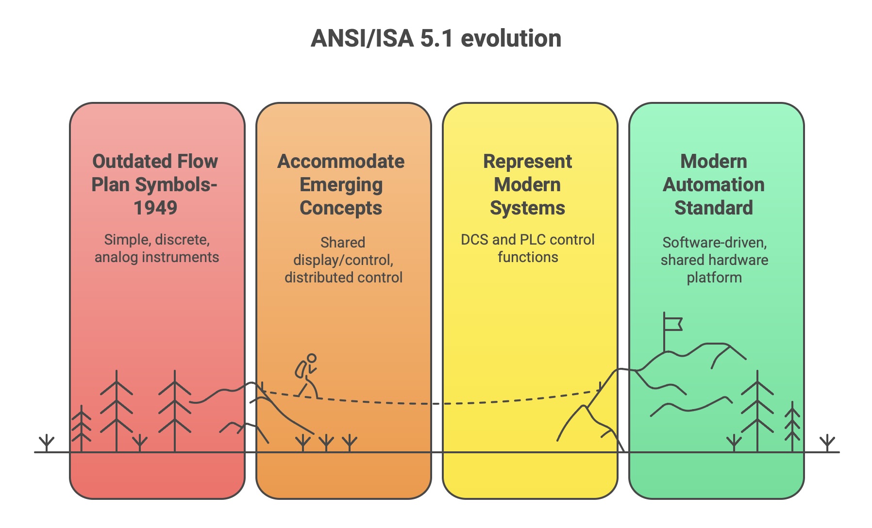
The evolution of this standard serves as a direct reflection of the technological evolution of the automation industry. The original 1949 title, with its focus on “Flow Plan Symbols,” suggests a world of simple, discrete, and often pneumatic or analog instruments depicted on a diagram. As technology advanced, so did the standard. Revisions were made to accommodate emerging concepts that were foreign to the original authors, such as “shared display/control,” “distributed control,” and “programmable control”. These updates were necessary to represent the functions of modern Distributed Control Systems (DCS) and Programmable Logic Controllers (PLCs), where control functions are often executed in software within a shared hardware platform rather than in distinct physical instruments.
This evolutionary path culminated in the most recent revision, ANSI/ISA-5.1-2024. A seemingly subtle but profoundly significant change was made in this version: the title was updated from “Instrumentation Symbols and Identification” to “Instrumentation and Control Symbols and Identification”. This change explicitly acknowledges that modern automation is less about individual “instruments” and more about integrated “control” functions. The standard is not a static relic but a living document, adapting continuously to provide a relevant and effective language for describing the state-of-the-art in industrial automation.
1.2 Purpose, Scope, and Industry-Wide Benefits
The fundamental purpose of the ANSI/ISA-5.1 standard is to establish a uniform and systematic means of designating, identifying, and depicting instruments, control devices, and their associated functions in technical documentation. It provides a comprehensive designation system that includes both graphical symbols and an alphanumeric identification code. The standard is intentionally designed as a consensus document rather than a mandatory one, a characteristic that provides it with the flexibility for widespread, interdisciplinary application across a vast array of industries. Its primary users are found in the chemical, petroleum, power generation, metal refining, pulp and paper, pharmaceutical, water and wastewater treatment, and numerous other continuous, batch, and discrete-part processing industries.
The standard acts as a universal language, a common tongue that enables clear and unambiguous communication among all stakeholders in a project’s lifecycle. Engineers, designers, operators, and maintenance personnel can use the standard as a conceptualizing aid, a design tool, a teaching device, and a concise means of communication in all forms of technical documentation, from initial design sketches to final construction drawings like Piping and Instrumentation Diagrams (P&IDs). The goal is to provide sufficient information to enable anyone with a reasonable amount of process knowledge to understand the means and purpose of the measurement and control systems without needing to be an instrumentation specialist.
The adoption of ISA-5.1 offers a host of tangible benefits that extend beyond mere technical clarity, positioning it as a strategic tool for economic performance and risk mitigation.
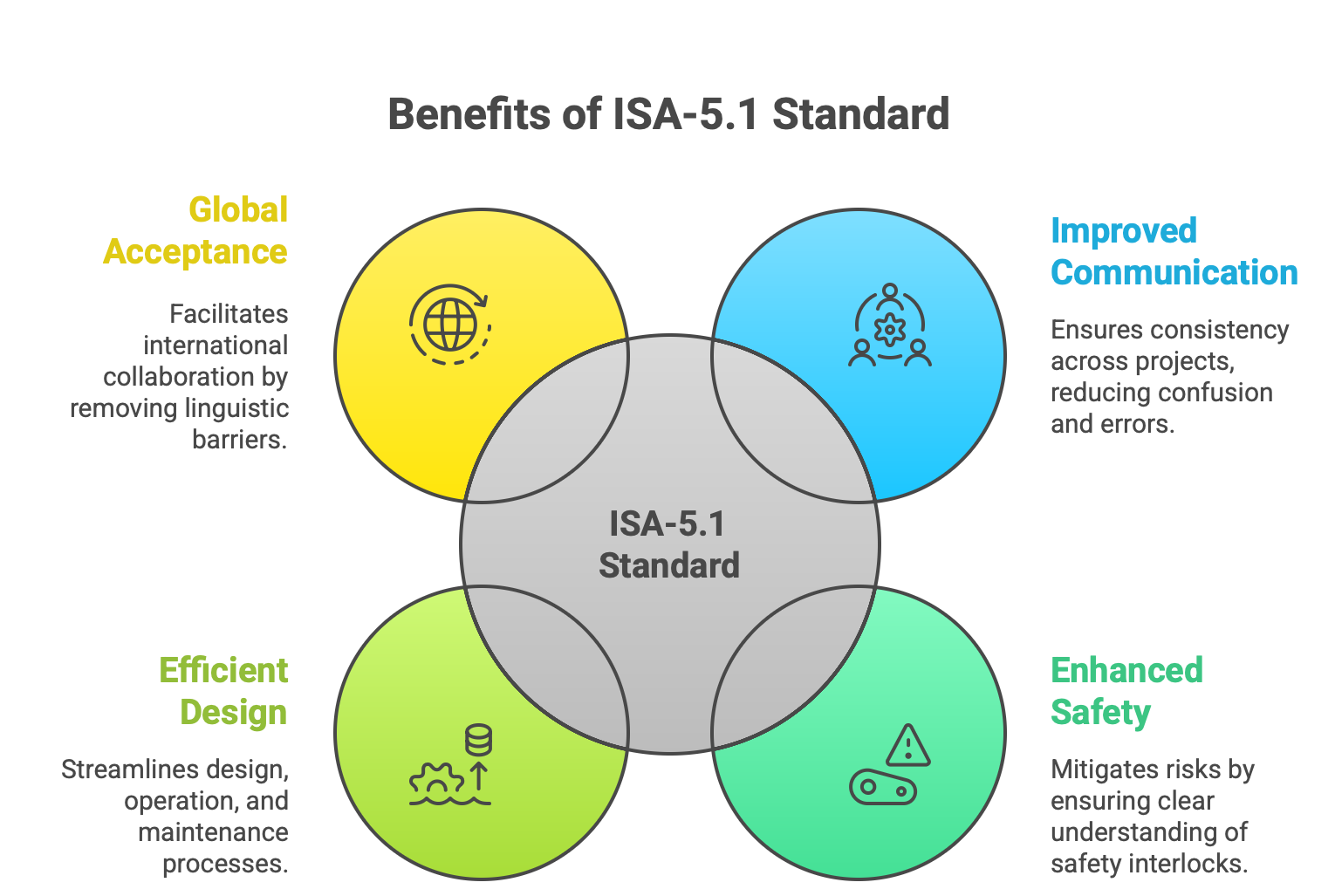
Improved Communication and Consistency: By providing a single, standardized methodology, the standard ensures consistency across projects, facilities, and even entire organizations. This uniformity dramatically reduces confusion, misinterpretation, and the errors that can arise when multidisciplinary teams collaborate. Fewer errors during design and construction translate directly into less rework, lower project costs, and faster commissioning schedules.
Enhanced Safety: In the high-hazard environments of process industries, misinterpretation of a control strategy can lead to catastrophic accidents, equipment damage, and environmental harm. By ensuring that documentation is clear and accurate, the standard is a critical tool for enhancing plant safety. A clear understanding of safety interlocks and control functions is paramount for safe operation, and ISA-5.1 provides the language for this understanding. This directly mitigates significant operational and financial risks.
Efficient Design, Operation, and Maintenance: The standard streamlines the entire lifecycle of a control system. During design, it provides the building blocks for creating clear P&IDs and functional diagrams. During operation, it gives operators an unambiguous view of the control system. For maintenance, the clear and accurate documentation simplifies troubleshooting, reducing plant downtime. In industries where downtime can cost millions of dollars per day, this efficiency is a major economic driver.
Global Acceptance: As an internationally recognized and widely adopted standard, ISA-5.1 facilitates collaboration with global partners, vendors, and engineering firms. It removes linguistic and regional barriers in technical communication, ensuring that a P&ID created in one country can be accurately interpreted by an engineering team in another.
Ultimately, the value of the standard is not confined to the neatness of a drawing. Its true impact is measured in the financial and operational stability of the enterprise. By reducing project costs, minimizing downtime, enhancing safety, and ensuring regulatory compliance, the ANSI/ISA-5.1 standard functions as a powerful tool for achieving operational excellence.
Part 2: Decoding the Language: The Instrument Identification System
The alphanumeric core of the ANSI/ISA-5.1 standard is its instrument identification system, commonly known as the “tag number.” This system provides a unique and functionally descriptive label for every instrument, device, and software function within a control system. Mastering this system is the first step toward fluency in the language of instrumentation.
2.1 Anatomy of an Instrument Tag
An instrument tag is a code composed of a series of letters and numbers that uniquely identifies a component and describes its function within a process. The standard structure combines two primary components: a Functional Identification and a Loop Identification. This core structure can be augmented with optional prefixes and suffixes to provide additional layers of information, such as the plant area or to distinguish between multiple instruments in a single loop.
A complete tag number might look like this: 10-PIC-101A
Optional Prefix (10-): This numerical prefix often designates the plant, unit, or geographical area where the instrument is located. For large facilities, this is crucial for organization.
Functional Identification (PIC): This is the series of letters that describes what the instrument does. In this example, “PIC” stands for Pressure Indicating Controller.
Loop Identification (101): This number identifies the specific control loop to which the instrument belongs. All components working together to control a single process variable share the same loop number.
Optional Suffix (A): This alphabetical suffix is used when multiple instruments of the same type exist within the same loop. For example, if a loop required two pressure controllers, they would be tagged PIC-101A and PIC-101B.
A critical principle of the standard is that identification should be based on function, not construction. For example, a level transmitter that operates by measuring the differential pressure of the fluid column in a tank is tagged as an LT(Level Transmitter), not a PDT (Pressure Differential Transmitter). Its purpose and function within the control loop are to measure level, regardless of the physical principle it uses to do so.
This functional approach is organized around the central concept of the “control loop.” The tag number is not merely a label for an isolated device; it is a coordinate that precisely places that device within a functional system. The loop number acts as the primary key, the common thread that links disparate physical components—such as a sensor, a controller, and a valve—into a single, cohesive functional unit. For instance, a flow control loop, identified as loop 101, would contain a Flow Transmitter (FT-101), a Flow Controller (FC-101), and a Flow Valve (FV-101). The first letter of the functional ID (F for Flow) is determined by the primary variable that the entire loop seeks to sense and control. Understanding this loop-centric principle is the key to correctly interpreting and applying the identification system.
2.2 Functional Identification: The Letter Code System
The functional identification is the descriptive heart of the instrument tag. It consists of a combination of one to five letters that define the instrument’s role. The meaning of each letter is context-dependent, determined by its position within the sequence.
First Letter: The initial letter designates the measured or initiating variable that the instrument or loop is concerned with. Examples include
Pfor Pressure,Tfor Temperature,Ffor Flow, andLfor Level. The first letter can also be a modifier; for example, in the tagPDI(Pressure Differential Indicator), thePis the measured variable, and the succeedingDacts as a modifier.Succeeding Letters: Letters that follow the first one describe the functions the device performs. These are categorized as:
Readout or Passive Functions: These typically provide information to an operator, such as
Ifor Indicate orRfor Record.Output or Active Functions: These perform an action or transmit a signal, such as
Cfor Control orTfor Transmit.Function Modifiers: These qualify another function, such as
Hfor High orLfor Low, often used with alarms or switches (e.g.,LAHfor Level Alarm High).
When an instrument has multiple functions, such as a Temperature Recording Controller (TRC), the passive function (R for Record) typically precedes the active function (C for Control). The standard also provides flexibility through “User’s Choice” letters (C, D, G, M, N, O in the first-letter position), which can be assigned specific meanings for a project, provided these definitions are clearly documented on a legend sheet.
The following table provides a comprehensive reference for the identification letters as defined by the ISA-5.1 standard, synthesized from multiple authoritative sources.
Table 1: ISA-5.1 Identification Letters
2.3 Loop Identification: Serial vs. Parallel Numbering
The loop number is the numerical portion of the tag that uniquely identifies a control loop. The ISA-5.1 standard accommodates two primary numbering philosophies, allowing organizations to choose the method that best suits their project management and operational needs.
Parallel Numbering: In this scheme, a number is combined with the process variable’s first letter to form the unique loop identifier. This approach allows the same number to be reused for different types of loops. For example, a single piece of equipment, such as reactor 101, could have a
TIC-101(Temperature Indicating Controller), aPIC-101(Pressure Indicating Controller), and anLIC-101(Level Indicating Controller). The combination of letters and numbers (T-101,P-101,L-101) makes each loop unique.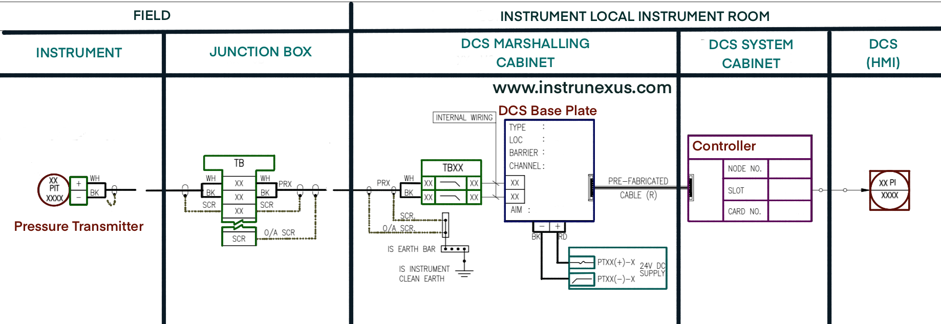
Serial Numbering: This method uses a single, unique numerical sequence for every loop in a plant or area, regardless of the process variable. Each new loop is assigned the next available number in the sequence. Under this system, one might find
TIC-101,LR-102(Level Recorder), andPIC-103. It would be invalid to have both aTIC-101and aPIC-101, as the loop number “101” would not be unique.
The choice between these two methods is not arbitrary; it reflects the organizational and engineering priorities of a project. Parallel numbering is often favored by process-engineering-driven organizations. It creates a logical grouping of instruments based on the primary process equipment they serve, which can be highly intuitive when viewing a P&ID. For instance, an engineer can quickly identify all primary control loops associated with “unit 101.”
Conversely, serial numbering offers administrative simplicity and is often preferred by I&C or systems-engineering-driven teams. It guarantees the uniqueness of every loop number, which simplifies management in large databases and instrument indexes. There is no need to cross-reference which numbers have been used for which variable type; the next loop simply gets the next number. This method is easier to automate and less prone to duplication errors on very large projects. The standard’s flexibility in allowing both approaches demonstrates its adaptability to different project philosophies and management styles.
Part 3: The Visual Lexicon: Graphical Symbols and Their Meanings
While the alphanumeric tag provides a functional and locational description, the graphical symbols of ANSI/ISA-5.1 provide the immediate visual context. These symbols are the building blocks used to construct diagrams, allowing engineers to quickly understand the type of instrument, its location, and its relationship to other components in the system.
3.1 Instrument and Function Symbols
The shape of the symbol used to enclose the instrument tag is the primary indicator of the underlying technology and function of the device. The standard defines four principal shapes.
Circle: This is the most fundamental symbol, often referred to as a “bubble” or “balloon”. It represents a discrete instrument—a standalone, physical device. Examples include a field-mounted pressure gauge, a panel-mounted chart recorder, or a single-loop pneumatic controller.
Circle inside a Square: This symbol denotes a function that is part of a shared display and shared control system. It is the standard representation for functions within a Distributed Control System (DCS), where a single hardware controller and operator interface are shared among many control loops.
Hexagon: This shape represents a computer function. It is used for more complex calculations, logic, or data processing tasks that are typically performed by a supervisory or process computer system that is distinct from the basic process control system (BPCS).
Diamond inside a Square: This symbol represents a Programmable Logic Controller (PLC) function. PLCs are commonly used for sequential logic, interlocks, and discrete control, and this symbol distinguishes their functions from those of a DCS or general-purpose computer.
The evolution of this symbol set tells a compelling story about the history of industrial control. The original standard relied primarily on the circle, reflecting an era of decentralized, analog control where each function corresponded to a dedicated physical instrument. The subsequent addition of the more complex shapes was a direct response to the digital revolution and the rise of centralized control systems. These modern symbols represent a paradigm shift from “one instrument, one function” to “one system, many functions.” The shape of the symbol on a P&ID therefore provides an immediate and powerful clue about the vintage and sophistication of the control technology being employed in a particular loop.
3.2 Location and Accessibility Identifiers
To further refine the visual information, horizontal lines are drawn through the center of the instrument symbols. These lines provide a precise and standardized method for indicating the physical location of the device and its accessibility to an operator.
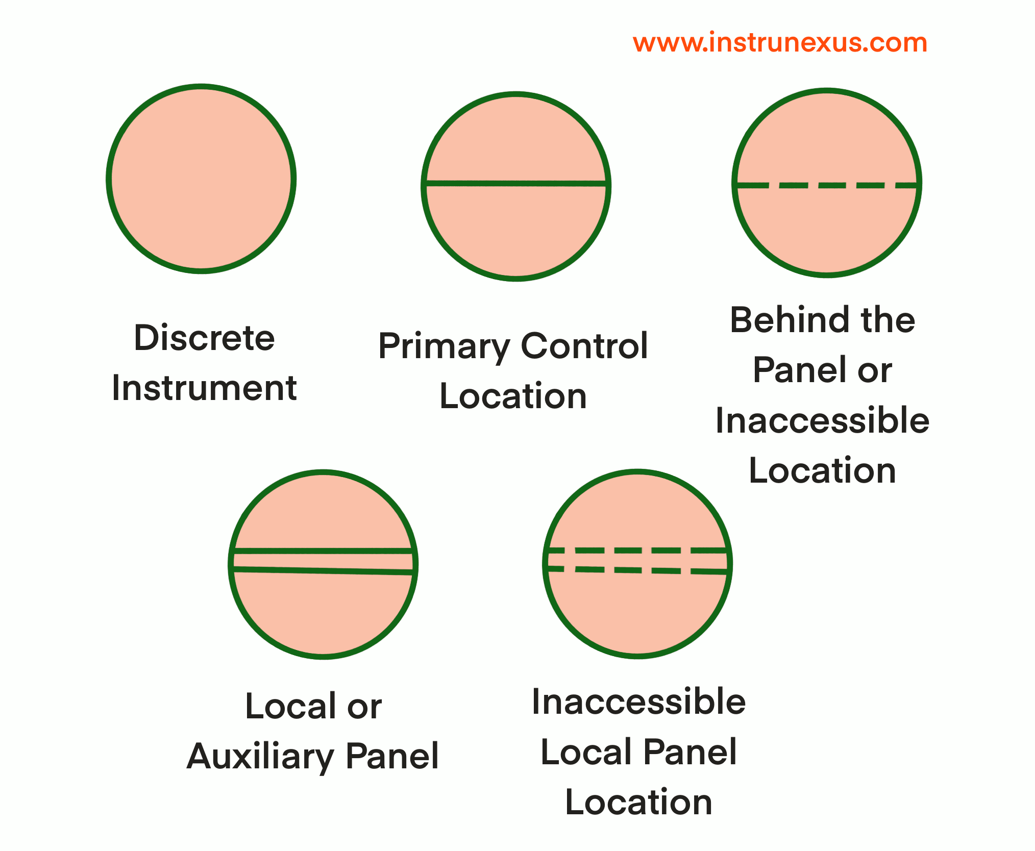
No Line: The instrument is field-mounted. It is installed in the process area, typically near the equipment it is monitoring or controlling.
Solid Horizontal Line: The instrument or function is located in a primary control location, which is normally accessible to the operator. This typically means the front of a main control panel in a central control room or on the primary display screen of a DCS.
Dashed Horizontal Line: The instrument is in a behind-the-panel or inaccessible location. While it may be in the control room, it is mounted in a cabinet, on a rack, or in another location not normally visible or accessible to the operator for routine tasks.
Double Solid Horizontal Line: The instrument is mounted on a local or auxiliary panel. This refers to a secondary control panel that is itself located in the field, not in the central control room.
Double Dashed Horizontal Line: This indicates an inaccessible local panel location, such as inside a field-mounted cabinet.
These seemingly minor graphical details carry significant practical weight, as they directly inform operational and maintenance workflows, safety procedures, and even staffing requirements. An instrument with “no line” (field-mounted) may require a maintenance technician to obtain a safe work permit, don personal protective equipment (PPE), and follow lockout-tagout procedures before they can perform calibration or repair. In contrast, a function with a “solid line” (control room) can often be diagnosed, tuned, or placed in manual mode by the operator directly from their console. A device with a “dashed line” (inaccessible) signals that a technician will need to access the back of a panel or open an enclosure, which may require specialized tools or an electrical work permit. These simple lines are thus encoded instructions that are critical for planning work safely and efficiently.
3.3 Connection and Signal Line Symbology
The lines connecting the various instrument symbols are as meaningful as the symbols themselves. They represent the pathways for process fluids, signals, and power, creating a complete map of the system’s interconnectivity. ISA-5.1 defines a comprehensive set of line symbols to differentiate these connections.
Process Connection Lines: Major process piping is typically shown with a thick, solid line. Instrument connections to a process line (e.g., impulse tubing for a pressure transmitter) are shown with a thinner, solid line.
Instrument Supply Lines: These lines indicate the power source for an instrument, such as:
AS: Air SupplyES: Electric SupplyGS: Gas SupplyHS: Hydraulic SupplyNS: Nitrogen SupplySS: Steam SupplyWS: Water Supply
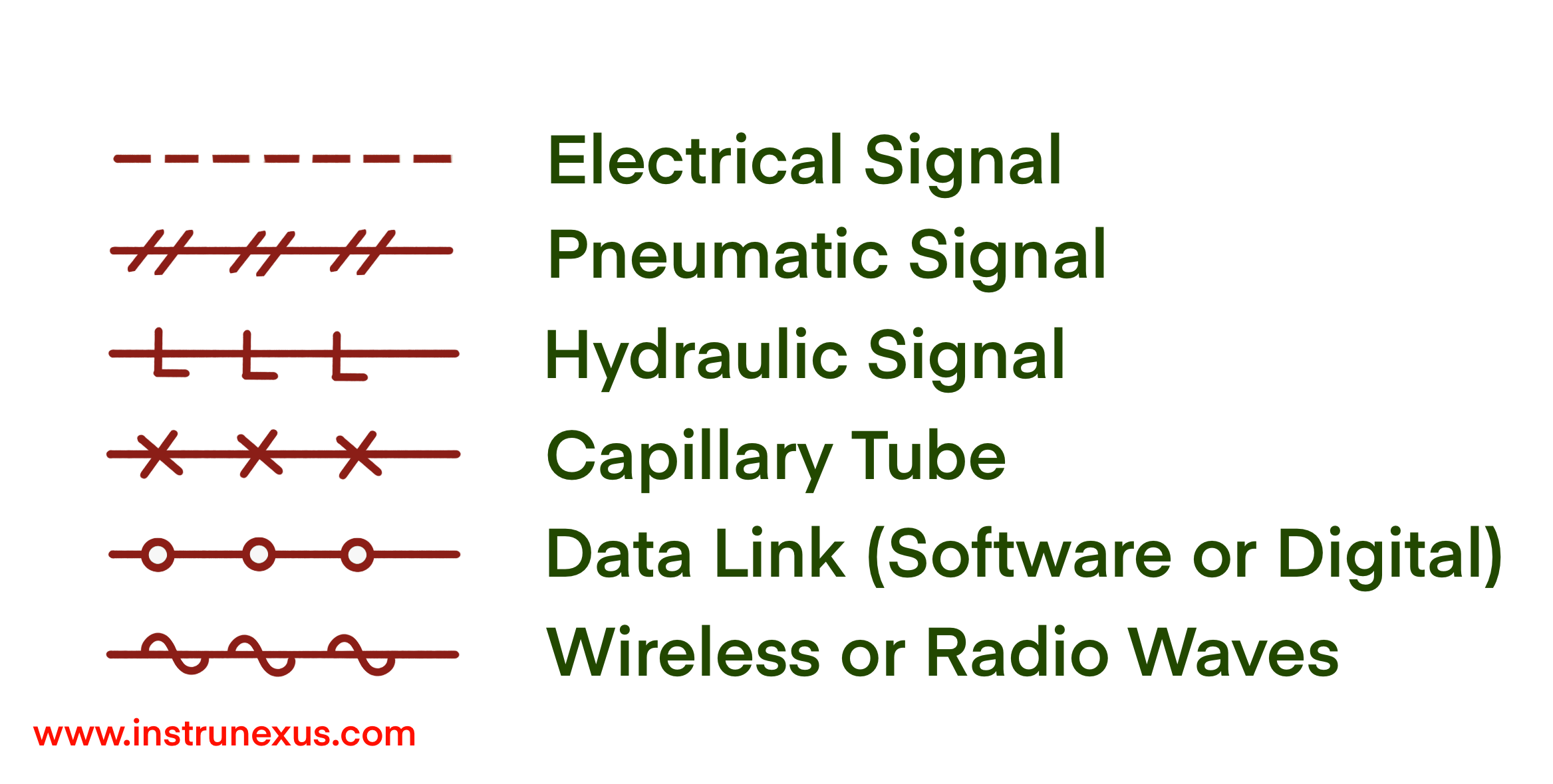
Signal Lines: These represent the communication links between instruments and are critical for understanding the flow of information. The most common types include:
Electrical Signal: A dashed line (
- - - - -) represents analog signals (e.g., 4-20 mA) or discrete binary signals.Pneumatic Signal: A solid line with double hash marks (
—//—) represents an instrument air signal (e.g., 3-15 psig).Hydraulic Signal: A solid line with the letter
Lintermittently placed along it (—L—L—).Capillary Tubing: A solid line with
Xs placed along it (—X—X—), used for filled thermal systems.Data Link (Software or Digital): A solid line with bubbles or circles placed along it (
—o—o—), representing communication via a fieldbus, Ethernet, or other digital protocol.Wireless Signal: A dashed line with symbols resembling radio waves (
- ~ ~ ~ -).
These line symbols allow an engineer to trace the entire “nervous system” of the plant. A P&ID illustrates not only the physical flow of process material through pipes and vessels but also the equally important flow of information and energy that enables control. One can follow the measurement data from a transmitter (often an electrical signal), to the decision-making logic in a controller (often a software link), to the final action at a control valve (often a pneumatic signal). This complete mapping is indispensable for troubleshooting. A control loop failure could originate in the sensor, the controller, the final element, or in any of the signal paths connecting them. The line symbology provides the necessary map to diagnose such faults systematically. The 2024 revision of the standard further enhanced this area by adding a new, dedicated table (Table 19) for symbols used specifically in instrument loop diagrams.
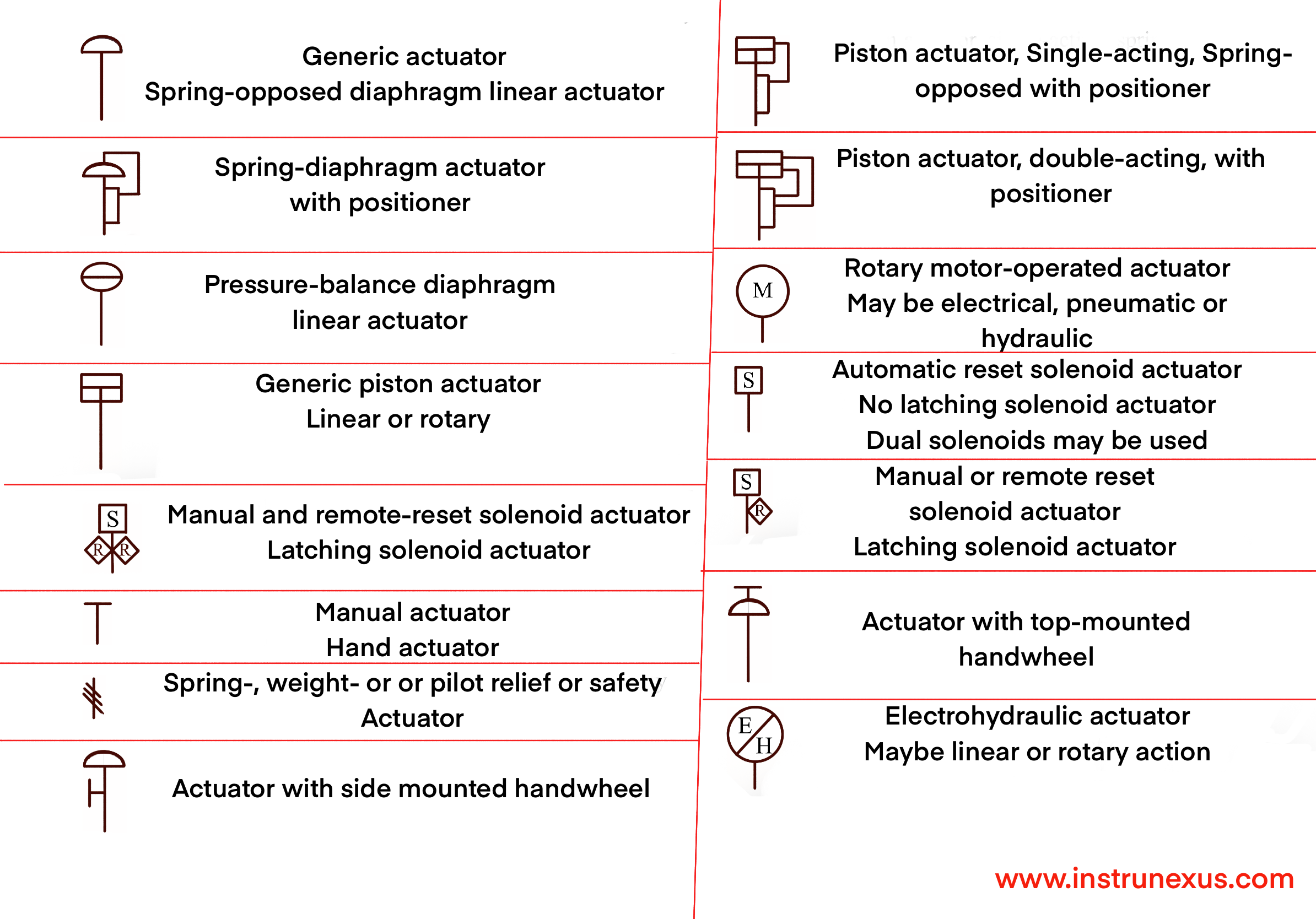
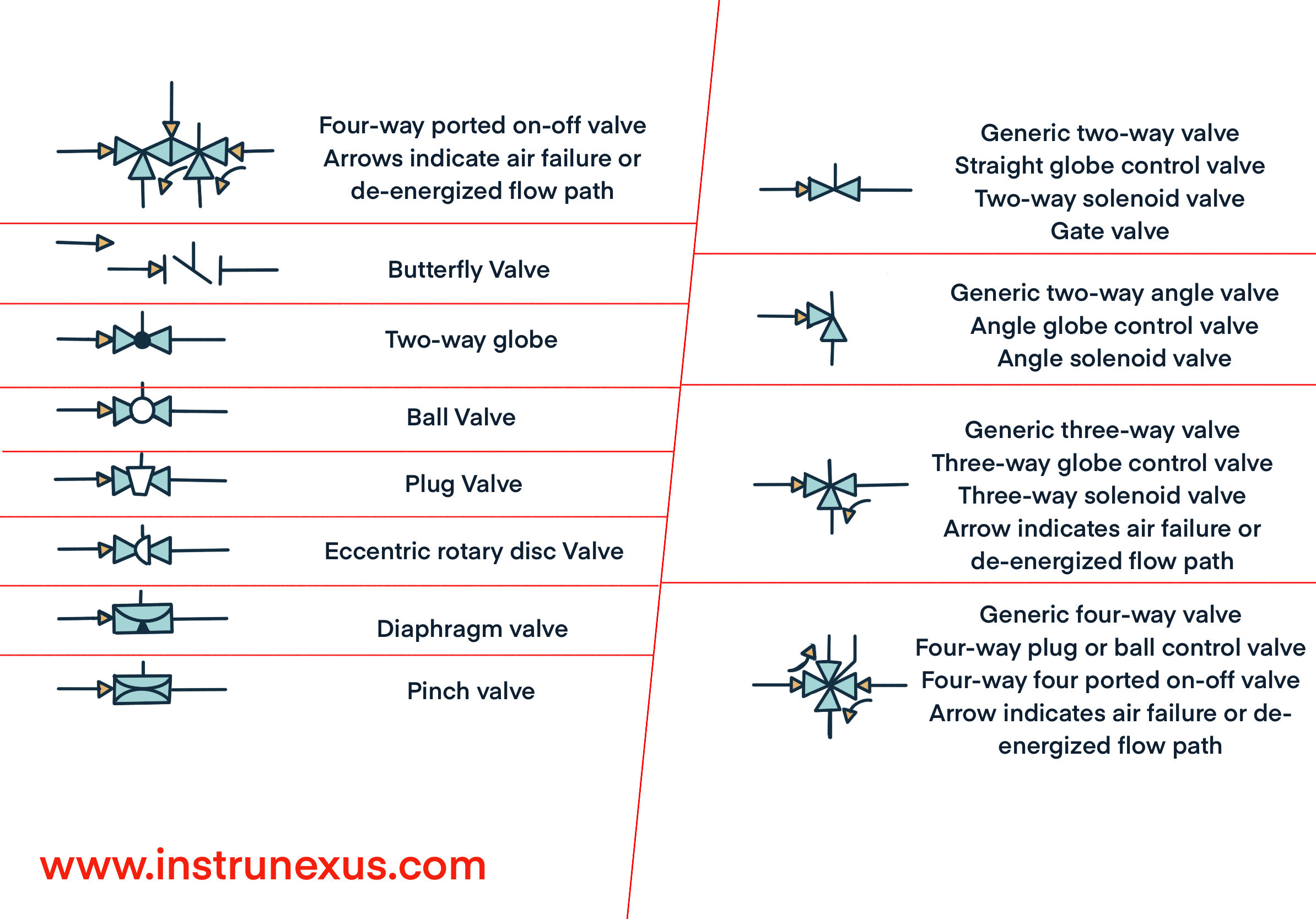
3.4 Final Control Elements and Actuators
The final control element is the device that directly manipulates a process variable, implementing the decision made by the controller. Most commonly, this is a control valve. The ISA-5.1 standard provides symbols to represent various types of valves (e.g., gate, globe, ball, butterfly, diaphragm) and the actuators that power them.
The valve body symbol gives an indication of its construction. For example, a standard 2-way valve is shown as two triangles pointing toward each other. A globe valve is often depicted with a filled-in circle between the triangles, while a ball valve uses an unfilled circle.
The actuator symbol is drawn above the valve body and indicates the method of operation. Common symbols include a semi-circle for a diaphragm actuator (common in pneumatic control) or the letter M for an electric motor actuator.
Perhaps the most critical piece of information conveyed by the final control element symbol is its fail-safe position. This indicates the state the valve will assume upon loss of its motive power (e.g., loss of instrument air or electricity). This is a fundamental safety design feature and is depicted with a small arrow on the actuator stem.
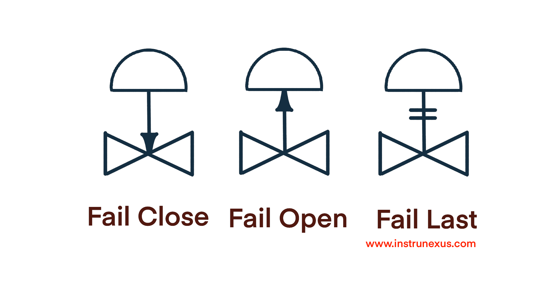
Fail-Closed (FC): An arrow pointing away from the valve body indicates that the valve will close on failure.
Fail-Open (FO): An arrow pointing toward the valve body indicates that the valve will open on failure.
Fail-Last/Lock (FL): The valve will remain in its last position on failure.
The fail-safe designation is not an arbitrary choice; it is a deliberate and critical safety engineering decision derived from a Process Hazard Analysis (PHA). For example, a valve controlling the flow of cooling water to a reactor must be specified as Fail-Open (FO) to ensure that a loss of power does not lead to an uncontrolled overheating reaction. Conversely, a valve controlling the flow of fuel to a burner must be specified as Fail-Closed (FC) to prevent a dangerous accumulation of unburnt fuel. The simple FO or FC designation on a P&ID is therefore a declaration of the intended safe state of the system during an upset or emergency. Misinterpreting this symbol or installing a valve with the incorrect fail-safe action can fundamentally compromise the safety design of an entire process unit.
Part 4: Synthesis and Application: ISA-5.1 in Practice
Having deconstructed the alphanumeric tags and graphical symbols, the next step is to synthesize these elements to understand their application in real-world engineering documents. The standard’s true power is realized when its components are combined to create a clear and comprehensive picture of a control system.
4.1 Reading and Constructing Piping & Instrumentation Diagrams (P&IDs)
Piping and Instrumentation Diagrams (P&IDs) are the definitive blueprints for a process plant. They are detailed schematic diagrams that show the interconnection of process equipment, piping, and the complete instrumentation and control system. While ISA-5.1 is not an all-encompassing P&ID standard—it does not define symbols for mechanical equipment like pumps or vessels—it is the authoritative standard for the instrumentation and control elements depicted on these diagrams.
A P&ID uses the full lexicon of ISA-5.1 tags and symbols to illustrate every monitoring point, control loop, and safety interlock in a process. To correctly interpret a P&ID, one must refer to the project’s Legend Sheets (also called Lead Sheets). These supplementary drawings serve as the “secret decoder ring,” defining all the symbols and the specific conventions used for that project, including any “User’s Choice” letter designations or unique numbering schemes.
A P&ID is best understood as a multi-layered information hub, where each layer of information is communicated through a specific aspect of the ISA-5.1 standard.
The Physical Layer: This consists of the process equipment (tanks, reactors, pumps) and the piping that connects them.
The Measurement and Control Layer: Superimposed on the physical layer, this is where ISA-5.1 comes into play. The graphical symbols (circles, squares, etc.) and their location identifiers (lines) show what instruments exist and where they are located.
The Information and Energy Layer: The various line symbols for electrical, pneumatic, and data signals map the “nervous system” of the plant, showing how the components in the control layer communicate with each other and receive power.
The Data Layer: The alphanumeric tags inside each symbol provide the unique identifier and functional description for every component, linking the graphical representation to detailed specifications in instrument databases and other documents.
By integrating these layers, the P&ID provides a single, cohesive view that bridges mechanical, process, and control engineering disciplines. ISA-5.1 provides the essential grammar and syntax for the control, information, and data layers, allowing these abstract concepts to be visualized and understood within the physical context of the plant.
4.2 Case Study: Analysis of a Complete Control Loop
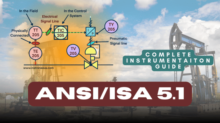
To illustrate how these elements come together, consider a typical temperature control loop for a heat exchanger, as it would be depicted on a P&ID. The objective of this loop is to control the temperature of a process fluid on the tube side by manipulating the flow of steam (the heating medium) on the shell side.
The P&ID snippet would show the following components, each telling part of the story:
The Sensor (Primary Element):
Symbol: A circle with the tag TE-205 inside. The circle indicates a discrete instrument. The tag identifies it as a Temperature Element (e.g., a thermocouple or RTD) in loop 205.
Location: The circle has no horizontal line, indicating it is field-mounted. A thin process line connects it to a thermowell symbol on the process fluid outlet pipe.
Connection: A solid line with
Xs (—X—X—) might be shown if it’s a filled-bulb system, or it might be directly connected to the transmitter.
The Transmitter:
Symbol: A circle with the tag TT-205 inside. The tag identifies it as a Temperature Transmitter in loop 205.
Location: The circle has no line, indicating it is also field-mounted, likely near the sensor.
Connection: A dashed electrical signal line (
- - - - -) originates from TT-205 and runs towards the control room. This line represents the 4-20 mA signal carrying the process temperature information.
The Controller:
Symbol: A circle inside a square with the tag TIC-205. The shape indicates this is a DCS function. The tag identifies it as a Temperature Indicating Controller in loop 205. The “I” for “Indicating” means the operator can view the temperature on their screen.
Location: A solid horizontal line runs through the symbol, indicating it resides in the primary control location (the DCS operator console).
Connection: The dashed electrical line from TT-205 terminates at this symbol. Another dashed electrical line exits the symbol, representing the controller’s output signal.
The Current-to-Pneumatic (I/P) Converter:
Symbol: A circle with the tag TY-205. The
Yindicates a relay, compute, or convert function.Location: No line, indicating it is field-mounted, typically near the control valve.
Connection: The dashed electrical output line from TIC-205 terminates here. A pneumatic signal line (solid line with double hash marks,
—//—) exits this device and runs to the control valve actuator. An instrument air supply line (AS) would also be shown connected to it.
The Final Control Element (Control Valve):
Symbol: A globe valve symbol on the steam inlet pipe with a pneumatic diaphragm actuator symbol on top. The tag TV-205 is adjacent to it, identifying it as the Temperature Valve for loop 205.
Fail-Safe Position: A small arrow on the actuator stem points away from the valve body, and the letters
FC(Fail-Closed) are noted nearby. This is a critical safety designation: if instrument air is lost, the steam supply will be shut off, preventing an uncontrolled overheat of the process fluid.Connection: The pneumatic signal line from TY-205 terminates at the actuator.
The Narrative of the Loop: By reading these symbols in sequence, an engineer can construct a complete operational narrative: “The temperature element TE-205 measures the process fluid outlet temperature. The field-mounted transmitter TT-205 converts this measurement into a 4-20 mA electrical signal and sends it to the DCS. The Temperature Indicating Controller function, TIC-205, which is accessible to the operator, compares this temperature to its setpoint. Based on the error, the DCS logic calculates a new output and sends a 4-20 mA signal to the field-mounted I/P converter, TY-205. The converter translates this electrical signal into a 3-15 psig pneumatic signal, which modulates the control valve TV-205. This valve adjusts the steam flow to the heat exchanger to maintain the process temperature at the setpoint. For safety, the valve is designed to fail closed upon loss of instrument air.”
This example demonstrates that a P&ID, drawn correctly using ISA-5.1, is not just a static “as-built” drawing. It is a powerful analytical tool. It allows engineers to mentally simulate control actions, predict system responses to disturbances, and systematically diagnose malfunctions by comparing the actual behavior of the loop to the intended functionality clearly depicted on the diagram.
4.3 Beyond P&IDs: Application in Other Technical Documents
While the P&ID is the most prominent application of ISA-5.1, the standard’s utility extends across the entire suite of engineering documents required for a project, ensuring consistency from conception to maintenance.
Process Flow Diagrams (PFDs): These are high-level conceptual drawings that show the main process streams and major equipment. Instrumentation is typically shown in a simplified form on PFDs, often only indicating the main control loops with a single controller symbol and tag (e.g., TIC-205) to convey the control strategy without cluttering the diagram.
Instrument Loop Diagrams: These are detailed wiring and tubing diagrams for a single control loop. A loop diagram for TIC-205 would show the specific terminal numbers for the wiring at the transmitter (TT-205), the junction boxes, the marshalling panel, and the DCS input/output card. It would also show details of the pneumatic tubing and air supply for the I/P converter (TY-205) and valve (TV-205). The instrument tags from the P&ID are the key identifiers on these diagrams.
Functional Logic Diagrams: For complex interlock and sequencing systems, logic diagrams are used to define the relationships between inputs (e.g., switches, transmitters) and outputs (e.g., motor starts, valve closures). The tags defined on the P&ID (e.g.,
LSH-301for Level Switch High) are used as the inputs and outputs in these logic diagrams, ensuring a clear link between the control strategy and its implementation.Electrical Schematics: These diagrams show the power distribution and wiring for electrical components, including motor-operated valves or electric heaters. The instrument tags are used to identify the control devices within these schematics.
The consistent use of ISA-5.1 tags and symbols across all these documents creates a “golden thread” of information. This thread allows an engineer, operator, or technician to trace a single instrument, like TT-205, from its high-level representation on the PFD, to its detailed connections on the P&ID, to its specific wiring terminations on the loop diagram. This traceability is crucial for preventing silos of information between different engineering disciplines (process, I&C, electrical) and is fundamental to effective project management, commissioning, and long-term maintenance.
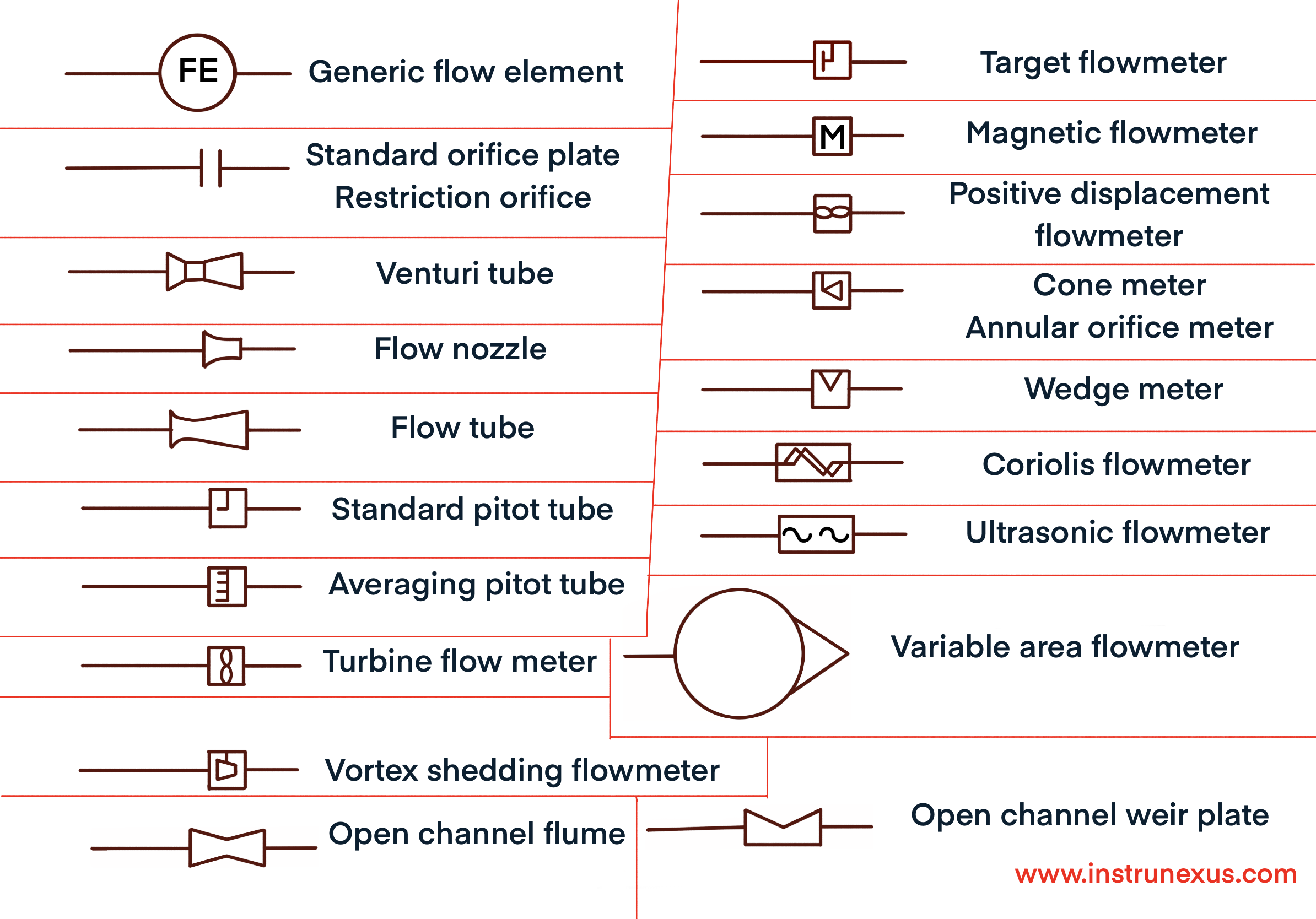
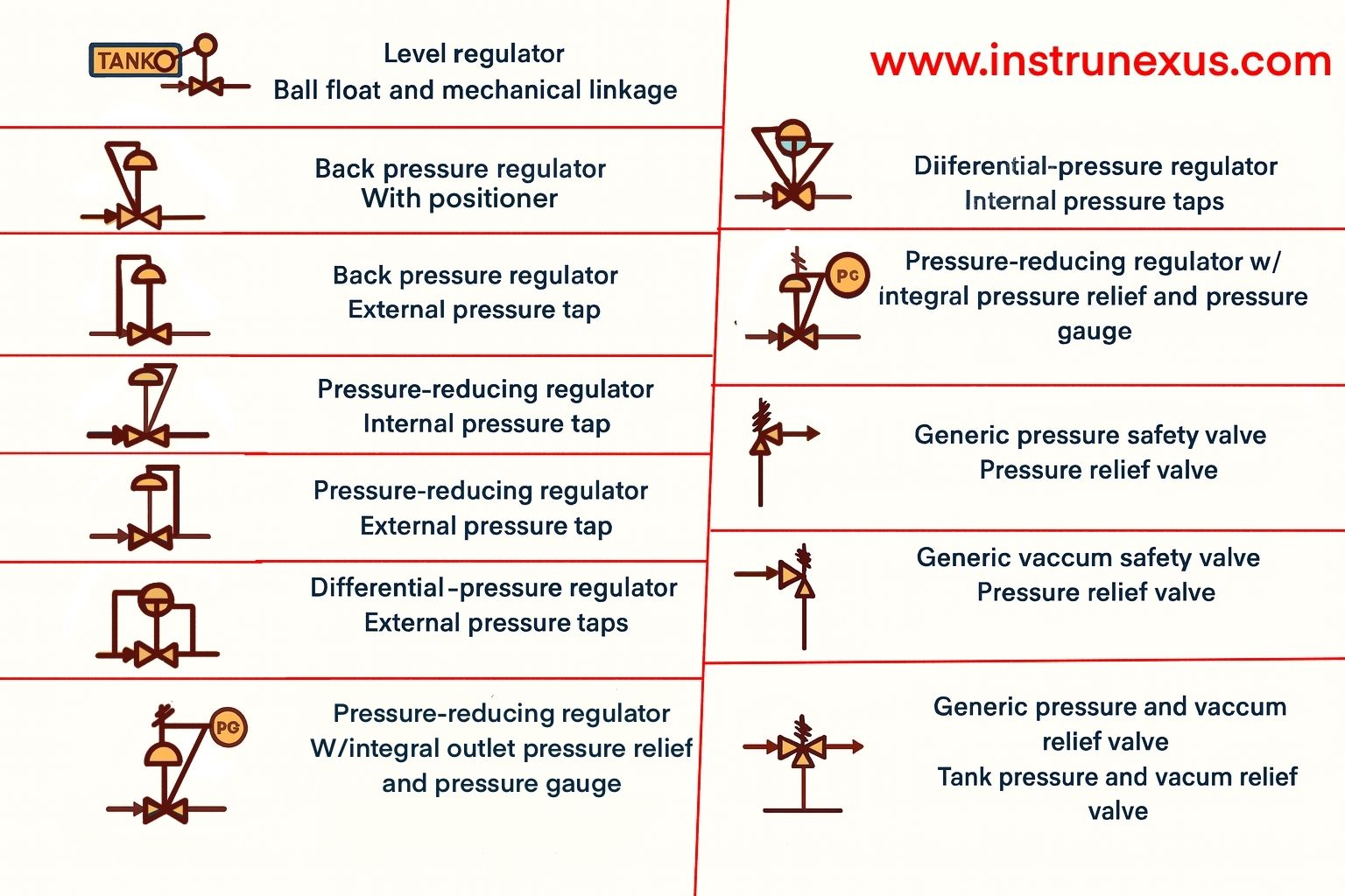
4.4 Other Instrumentation symbols in conventional usage
Part 5: The Evolving Standard and Future Outlook
The ANSI/ISA-5.1 standard is not a static document; it is subject to periodic review and revision to keep pace with technological advancements and evolving industry practices. Understanding the recent changes and adhering to best practices for implementation are essential for leveraging the standard to its full potential.
5.1 Navigating Recent Revisions (2022 & 2024)
In recent years, the ISA5 committee has undertaken significant work to update and improve the standard. The 2022 revision of ISA-5.1 was primarily focused on providing usage clarifications and correcting typographical and technical errors that had been identified in the previous 2009 version. This served as an important interim update to provide a corrected baseline for users.
The ANSI/ISA-5.1-2024 revision, however, introduced more substantial changes aimed at enhancing clarity, relevance, and usability. Key updates include:
Title Change: As previously noted, the title was changed to “Instrumentation and Control Symbols and Identification.” This was a deliberate move to emphasize that the standard encompasses symbols for modern control functions, which are often software-based, in addition to traditional discrete instruments.
Improved Readability: The document was reorganized to improve its logical flow. For example, notes related to a specific table are now placed immediately following that table, rather than being grouped together elsewhere. This makes the standard easier to navigate and interpret.
New Symbols and Technology: New symbols and notations were added to reflect advances in automation technology, ensuring the standard remains current and applicable to modern control systems.
Modularization via Technical Reports (TRs): The most significant structural change in the 2024 revision was the decision to move the extensive informative annexes from the main standard into two separate, standalone Technical Reports (TRs).
ISA-TR5.1.02-2024, Instrumentation and Control – Identification System Guidelines: This report provides detailed guidance, rationale, and examples for applying the instrument identification and tagging system.
ISA-TR5.1.03-2024, Instrumentation and Control – Graphic Symbol Guidelines: This report offers a rich collection of examples and guidance on the application of the graphical symbols.
This modularization represents a sophisticated evolution in standards development strategy. The main ANSI/ISA-5.1 standard now contains the core, normative requirements—the essential rules that must be followed to claim compliance. The TRs contain the informative guidance—the “how-to” information and extensive examples.
This separation offers several advantages. First, it streamlines the core standard, making it more concise and focused on the fundamental rules. Second, it provides greater flexibility and agility. The TRs can be updated and expanded more frequently with new examples and guidance to keep pace with rapid technological change, without requiring the full, rigorous ANSI revision process that the normative standard must undergo. This strategy separates the stable, foundational rules from the dynamic, application-specific examples, optimizing both documents for their respective purposes and ensuring the entire system remains relevant and useful for practitioners. Users are now strongly encouraged to use these two TRs in conjunction with the main standard to gain a complete understanding of its application.
5.2 Recommendations for Implementation and Best Practices
While ISA-5.1 provides a robust and flexible framework, its successful implementation depends on disciplined application and clear organizational procedures. Adhering to the following best practices is critical for maximizing the benefits of the standard.
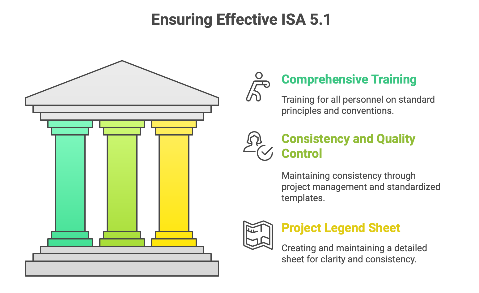
Comprehensive Training: All personnel involved in creating, reading, or using instrumentation documents—including engineers from all relevant disciplines, designers, operators, and maintenance technicians—must be trained on the principles of the standard and the specific conventions adopted by the organization.
Consistency and Quality Control: For large or complex projects, ensuring consistent application of the standard can be a challenge. This requires strong project management, the use of standardized templates, and a formal quality control process for reviewing and approving all technical documents. The use of modern P&ID software that incorporates the latest ISA-5.1 symbol libraries can greatly aid in enforcing consistency.
The Central Role of the Legend Sheet: The flexibility built into the ISA-5.1 standard, such as the “User’s Choice” letters and optional numbering schemes, is a strength, but it can become a source of confusion if not properly managed. The single most important best practice for successful implementation is the creation and maintenance of a detailed Project Legend Sheet (or Lead Sheet).
The Legend Sheet functions as the “legal contract” for a project’s P&IDs. It is the definitive document where all project-specific decisions, customizations, and interpretations of the standard are formally recorded. A proper legend sheet should include: * A complete library of all graphical symbols used on the project’s P&IDs. * A clear definition of the loop numbering philosophy being used (serial or parallel) and the structure of the tag numbers. * A table defining the meanings assigned to any “User’s Choice” letters. * A legend for all line types (process, pneumatic, electrical, data, etc.). * Any other project-specific notations or symbols.
By establishing this clear and comprehensive reference at the outset of a project, the Legend Sheet ensures that the language of ISA-5.1 is applied consistently and unambiguously by everyone involved. It transforms the standard from a general guide into a precise and powerful communication tool tailored to the specific needs of the project.
Conclusion
The ANSI/ISA-5.1 standard for Instrumentation and Control Symbols and Identification is far more than a mere collection of symbols and codes. It is the universal grammar of industrial automation, a dedicated language that has evolved for over 75 years to meet the demands of an ever-advancing technological landscape. From its origins in describing simple analog instruments to its current form capable of representing complex, software-driven distributed control systems, the standard provides the essential tools for communicating concepts, facts, intent, and knowledge about measurement and control systems.
Its systematic approach to both alphanumeric tagging and graphical representation allows for the creation of dense, multi-layered documents like P&IDs that serve as the central hub of information for a process plant. By mastering this language, engineers, technicians, and operators can achieve a level of clear, unambiguous communication that is fundamental to ensuring the safety, efficiency, and profitability of their operations.
The standard’s recent evolution, particularly its modularization into a core normative document supported by detailed informative technical reports, demonstrates a forward-looking strategy to maintain relevance and agility in the face of rapid technological change. For organizations that commit to its disciplined implementation—through comprehensive training, consistent application, and the crucial use of project-specific legend sheets—the adoption of ANSI/ISA-5.1 is not simply a technical choice. It is a strategic investment in operational excellence, a foundational element for building and maintaining control systems that are safe, reliable, and effective.