

Comprehensive Analysis of Instrumentation Design Engineering Process Flow and Deliverables
Section 1: Foundational Framework of Instrumentation Design Engineering (IDE)
Instrumentation and Control (I&C) design engineering constitutes a foundational discipline within capital projects, particularly in process-oriented sectors such as oil and gas, petrochemicals, and pharmaceuticals. The practice involves designing the complex systems necessary to measure, regulate, and safeguard industrial processes, translating conceptual operational needs into physical reality.
1.1 Role, Mandate, and Criticality of C&I Engineering
I&C design is far more than just specifying sensors and controllers; it defines the operational intelligence of an industrial facility. A robust, well-executed I&C system ensures the functionality, efficiency, safety, and operational longevity of the entire facility. I&C decisions critically influence the process design, which, in turn, determines the project’s capital cost, execution schedule, long-term operability, and safety profile.
The mandate of C&I engineering is to provide the detailed “blueprint” that guides the construction, operation, and regulatory compliance of the plant. This involves establishing key process parameters and control objectives early in the project lifecycle. Because the complexity of modern industrial automation requires managing thousands of interconnected data points, maintaining data consistency and quality is paramount. When dealing with extensive capital projects, the management of linked documentation (such as Instrument Indices, Datasheets, and I/O Lists) demands a shift from manual, document-centric methods to an integrated, data-centric approach. Specialized engineering software is leveraged to facilitate real-time collaboration between instrumentation, electrical, and other disciplines, ensuring that changes made in one area (e.g., a tag number revision on a P&ID) immediately propagate across all related deliverables, thereby maintaining accuracy across the entire project scope.
1.2 Governing Standards and Compliance Frameworks
The systematic identification and depiction of control systems relies heavily on internationally recognized standards to ensure clarity and consistency across engineering teams, procurement activities, and construction efforts.
Standards and Guidelines
The International Society of Automation (ISA) establishes fundamental standards globally recognized for C&I work:

ANSI/ISA 5.1: This standard specifies the procedure for the graphical representation and identification of measurement and control equipment, forming the basis for Piping and Instrumentation Diagrams (P&IDs). The symbols and identification methods provided by this standard serve as conceptualizing aids, design tools, and concise means of communication across all technical, procurement, construction, and maintenance documents.
ISA-20: This standard defines template forms for instrument specifications, ensuring a uniform method for generating datasheets across projects and clients.
Safety Standards (ISA-84 and IEC 61511): The ISA-84 standard, which is strongly aligned with IEC 61511, governs the design and operation of Safety Instrumented Systems (SIS). These standards ensure that specific safety requirements are met through documented design, verification, and validation processes.
Integration Standards: Standards such as ISA-88 (for Batch Control Systems used in pharma or food industries) and ISA-95 (for integrating enterprise planning systems, ERP, with plant control systems, MES/DCS) establish frameworks for complex control logic and system integration.
International standards, including those from the International Electrotechnical Commission (IEC), ISO, ATEX (for hazardous environments), and NAMUR (user association for automation technology), set rules for safety, design, calibration, testing, and integration of process control systems. Compliance with these standards is not optional; it dictates the integrity of the design and the validity of equipment certification and approval.
1.3 Project Lifecycle Phasing and C&I Scope Evolution
The development of C&I systems progresses through distinct phases, ensuring scope maturity, cost control, and risk mitigation before major capital commitment.
Conceptual Design (FEL 1): The initial phase begins with defining the overall scope, key process parameters, and overall functionality required from the system. This involves preliminary estimation of the control system requirements, leading to initial I/O counts and high-level configuration planning.
Front-End Engineering Design (FEED) (FEL 2/3): This is a critical stage focused on establishing the project’s technical foundation, confirming viability, and optimizing costs. FEED aims to reduce risks by finalizing the scope definition before moving into the high-cost execution phase.
Detailed Engineering (EPC Phase): Building upon the foundation laid in FEED, this phase develops precise drawings, specifications, calculations, and construction-ready documentation. This is where cross-discipline coordination is maximized to ensure alignment across mechanical, piping, electrical, and civil scopes.
One crucial implication of the phase structure is the mandatory early integration of safety requirements. If requirements under ISA-84/IEC 61511 are fully addressed only during Detailed Engineering, expensive redesigns become common. Instead, starting in the Conceptual and FEED stages, C&I engineers work to incorporate Inherently Safer Design (ISD) principles. This means aiming to reduce or eliminate hazards through design (e.g., designing systems to make hydraulic overpressure impossible or minimizing waste streams). Resolving safety issues identified in early reviews prevents significant technical and financial setbacks during the final design execution.
Section 2: The Instrumentation Design Engineering Process Flow
The instrumentation design engineering process flow is a structured, phase-gated methodology essential for managing the complexity and safety requirements of large industrial projects. The flow proceeds through six major phases, each defined by specific activities, deliverables, and formal review gates.
2.1 Phase 1: Conceptual Design (Scope Definition
The design journey commences with a clear understanding of the facility’s operational needs.
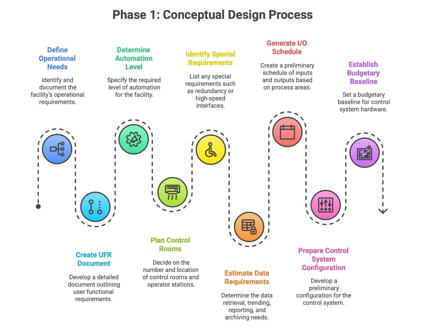
Activity: Defining Operational Needs and User Functional Requirements (UFR)
In this phase, engineers and stakeholders define the scope, control objectives, and overall functionality required. The User Functional Requirements (UFR) document is created through detailed discussions with the client, specifying critical operational parameters. These requirements cover:
The required level of automation (sequencing, interlocking, or full automation).
The number and location of control rooms and operator stations.
Any special requirements, such as redundancy, high-speed interfaces, or future expansion capability.
Requirements for data retrieval, trending, reporting, and archiving.
Activity: Preliminary Sizing and Configuration
Initial technical estimation begins with generating a preliminary Input/Output (I/O) Schedule based on the process areas and initial P&IDs. This schedule, along with the UFR, allows for the preparation of a preliminary control system configuration. Factors considered include logical and physical plant areas, location of substations/Motor Control Centers (MCCs), and the I/O count estimations. This early technical estimation establishes the budgetary baseline for control system hardware, making rigorous cost monitoring essential to manage project risk.
2.2 Phase 2: Front-End Engineering Design (FEED) and Feasibility
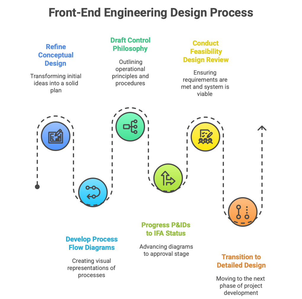
FEED refines the conceptual design into a solidified technical and economic plan.
Activity: Process Blueprints and Control Philosophy
Process Flow Diagrams (PFDs) and preliminary Piping and Instrumentation Diagrams (P&IDs) are developed based on the Process Engineering Heat and Material Balance (HMB). The C&I team drafts the Control Philosophy and initial Control Narrative, outlining the operating principles, key variables, and intended operational procedures. P&IDs at this stage typically progress to Issued for Approval (IFA) status.
Gate Review: Feasibility Design Review
A formal review is mandatory before transitioning into the resource-intensive Detailed Design phase. The primary objective of the Feasibility Design Review is to check rigorously that the client’s defined requirements (UFR) are being met and that the chosen control system configuration remains viable. Successful passage through this gate ensures that the project has a sound technical foundation.
2.3 Phase 3: Detailed Engineering Design (Execution Core)
This phase represents the core of the IDE effort, moving from general design intent to specific, implementable instruction sets.
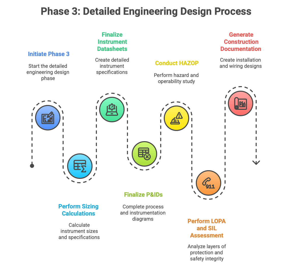
Activity: Sizing, Selection, and Specification
Detailed instrument sizing calculations are performed, covering complex components such as control valves, flow meters, and safety relief valves. These calculations rely on receiving critical process data, including the HMB summary, Line List, and process specifications.
The output of this calculation and selection effort is the final, precise Instrument Datasheet. Datasheets provide detailed specifications—measurement range, accuracy, resolution, linearity, operating conditions (T/P), material of construction, and electrical requirements. These specifications, standardized using ISA-20 templates, are critical as they form the contractual basis for procurement and govern compliance with required certifications (e.g., ATEX, SIL rating).
Activity: P&ID Finalization and Safety Assessment Gates
P&IDs are finalized, progressing through key milestones. The P&IDs are first issued for HAZOP (IFH) status. The HAZOP (Hazard and Operability Study) is performed using methods like What-if or FMEA (Failure Mode and Effect Analysis) to systematically check for deviations from design intent and identify potential hazardous scenarios.
If the HAZOP identifies risks requiring protective layers, a LOPA (Layer of Protection Analysis) and subsequent SIL (Safety Integrity Level) assessment are conducted. The C&I team must then incorporate the findings—such as adding a Safety Instrumented Function (SIF)—into the Control Narrative and the specific instrument datasheets to ensure the final detailed design resolves all identified safety issues. Only after safety verification is complete and documented do the P&IDs achieve Issued for Construction (IFC) status.
Activity: Installation and Wiring Design
The final construction documentation is generated, including Instrument Location Layouts, detailed Hook-up Drawings, Loop Diagrams, and Cable Schedules. This documentation allows construction teams to physically place, connect, and wire the instruments.
2.4 Phase 4: Procurement, Installation, and Integration
Once datasheets are issued for purchase (IFP), the procurement phase begins. Component selection requires analyzing vendor datasheets against simulation and test results to ensure performance and longevity.

The physical installation involves mounting instruments, control panels, laying extensive cabling, and integrating communication systems. Throughout this stage, meticulous data management is crucial. Documentation is maintained in real-time to ensure every physical change and installation detail is traceable, initiating the process of creating the “As-Built” records.
2.5 Phase 5: Testing, Commissioning, and Handover
This phase validates the functionality and safety of the installed system.
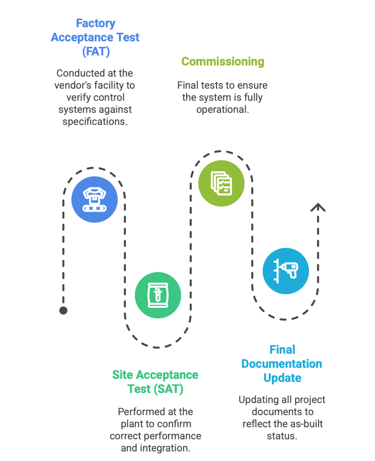
Activity: Factory and Site Testing
Factory Acceptance Test (FAT): Conducted at the vendor’s facility, the FAT verifies the functionality of the control systems (DCS/PLC) against the finalized Control Narratives and design specifications. A detailed Control Narrative is essential here, as its clarity minimizes programming ambiguity and ensures an efficient, accurate validation of the configured logic.
Site Acceptance Test (SAT) and Commissioning: After installation, post-installation checks, loop checks, and functional tests are performed in the plant environment to confirm correct performance and integration.
Activity: Final Documentation
All project documents, including P&IDs, wiring diagrams, and indices, are formally updated to their As-Built or Re-Issued For Construction (Re-IFC) status, providing the definitive baseline documentation for plant operation and maintenance.
Section 3: Categorized C&I Deliverables: Foundation Documents
The foundational deliverables define the functional architecture and specific technical parameters of every instrument.
3.1 Piping and Instrumentation Diagrams (P&IDs)
P&IDs serve as the single most critical engineering drawing, acting as the centralized repository for process flow, equipment identification, and control scheme representation.

Purpose and Content
P&IDs depict the functional relationship of piping, equipment, controllers, and instrumentation using a standardized set of symbols and codes. They are crucial for coordination among process, controls, and electrical engineers, aiding in the development of detailed control descriptions and serving as the primary document for Hazard and Operability Studies (HAZOP).
The instrumentation symbols must adhere to ANSI/ISA 5.1-2024, ensuring a standardized method to graphically depict all measurement and control equipment. Critically, P&IDs convey the interconnectivity of automated components, showing not just the presence of a device but how it is interlocked with other systems (e.g., demonstrating that a pump’s status is wired to control a seal water solenoid valve).
Issuance Status Significance
The status of the P&ID directly dictates the progress of the entire project. The progression from Issued for Review (IFR) in Pre-FEED, to Issued for Approval (IFA), and then Issued for HAZOP (IFH) during FEED, and finally Issued for Construction (IFC) in Detailed Engineering, represents formal sign-offs that unlock subsequent engineering and procurement activities.
3.2 Instrument Index (The Master Database)
The Instrument Index functions as the master database, or list, for every single tagged instrument within the project scope. It serves as the authoritative data reconciliation tool, linking functional design to physical installation and maintenance records.
Key Content and Role
The index is fundamental for Procurement, Construction, and Maintenance, providing crucial reference data:
Identification: Tag Number, Product Name, and Model Number.
Location and Function: The physical location within the plant and the functional purpose (measurement, control, safety).
Specifications: Key technical details like measurement range, accuracy, and output signal type.
Traceability: Documentation references, including associated Datasheet numbers, P&ID numbers, calibration procedures, and loop wiring diagrams.
Logistics: Identification of the instrument vendor or manufacturer.
The integrity of the Instrument Index is critical; it is the link between Process requirements and physical execution. Any discrepancy between the P&ID and the Index will lead to errors in the Material Take-Off (MTO) and procurement, creating severe delays and cost overruns during the construction phase.
3.3 Instrument Data Sheets and Specifications
Instrument Data Sheets are the detailed technical and commercial documents that define the exact requirements for each instrument prior to requisition.
Content Requirements
Prepared by the instrumentation process engineer, often utilizing vendor catalogs and specific calculations, the datasheet specifies:
Process Conditions: Detailed operating conditions, including temperature, pressure range, and fluid composition, typically derived from the Heat and Material Balance (HMB) and Line List.
Performance Characteristics: Technical performance requirements such as accuracy, linearity, response time, stability, and sensitivity.
Physical and Material Details: Materials of construction (crucial for compatibility with process fluids), physical dimensions, and weight.
Electrical/Safety Requirements: Power input, voltage, current, and hazardous area classification ratings.
The datasheet dictates the vendor’s required technical compliance. It is the primary document used to obtain quotes, and it commits the vendor to meeting both the technical specifications and any required third-party Certifications (involving intense engineering review and rigorous physical testing) or Approvals (administrative confirmation of compliance).
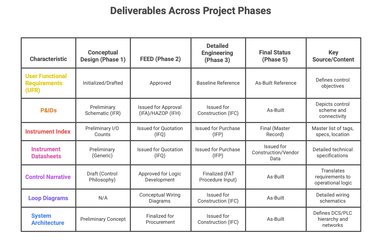
Table 1 illustrates the maturation of key foundational documents across the project phases.
Table 1: C&I Deliverables by Project Phase and Issuance Status
Section 4: Categorized C&I Deliverables: Control System and Logic
These deliverables define the software, logic, and architecture required for automated control and monitoring, effectively constituting the functional intelligence of the plant.
4.1 Control Philosophy and Control Narratives
The Control Narrative is a formal, descriptive document that outlines the operating principles and key variables of the control program. It serves as a crucial interface, translating abstract process design requirements into tangible operational logic.
Key Content and Functional Use
The document provides a comprehensive understanding of the process behavior and expected performance. Key elements include:
Descriptions of how the process should operate under normal and abnormal conditions.
Specific requirements for interlocking, sequencing, and full automation (aligned with the level of automation required in the UFR).
Explicit specifications for operational parameters such as alarm set points and shutdown values, ensuring safe and efficient operation.
The Control Narrative is the direct basis used by automation engineers to develop configuration code for Distributed Control Systems (DCS) or Programmable Logic Controllers (PLC). It also serves as essential documentation for operator training, enabling personnel to understand process equipment and variables. The quality and completeness of the narrative are directly linked to project efficiency. An ambiguous or incomplete narrative forces the control system vendor to make interpretations, leading to configuration errors that must be resolved during the costly Factory Acceptance Test (FAT). A thorough narrative minimizes this ambiguity, ensuring that the configured system accurately meets the operational goals from the outset.
4.2 Input/Output (I/O) Lists and Schedules
The I/O list is the fundamental link between the physical world (field instruments) and the digital control platform (DCS/PLC).
Purpose and Development
The list maps every instrument tag number to a specific physical or logical channel within the control system hardware. While a preliminary I/O schedule is prepared during Conceptual Design to estimate hardware costs, the final I/O list includes exhaustive detail required for system configuration.
Key Content
Each entry in the I/O list typically includes:
Instrument Tag Number and Service Description.
I/O Type (Analog Input, Digital Output, etc.).
Signal Type (e.g., 4-20 mA, Modbus, discreet contact).
The exact control system cabinet, module, and channel address allocated to the signal.
Safety Classification (e.g., related to SIS).
4.3 Control System Architecture Drawings and Specifications
These deliverables define the physical and logical structure of the entire control infrastructure.
Content and Hierarchy
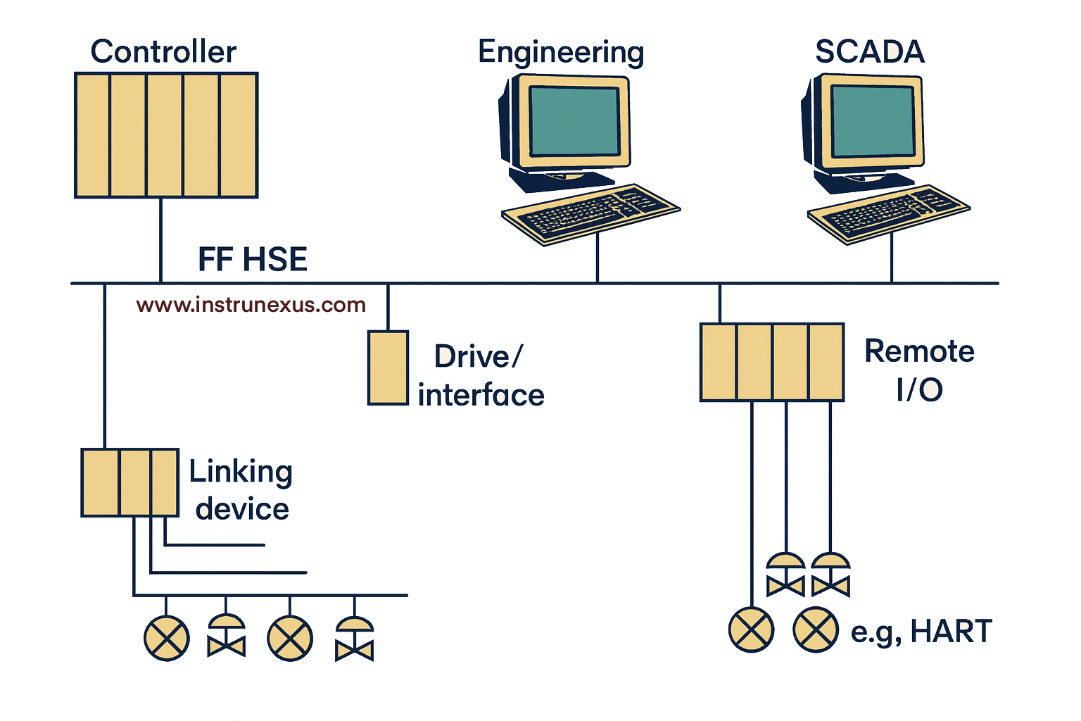
The System Architectural Drawing illustrates the system’s topology, encompassing the hierarchy of controllers, communication networks (including redundancy requirements), control rooms, local operator stations, and interfaces to higher-level management systems (such as MES or ERP systems).
The associated specifications detail the necessary hardware components, including the type of DCS/PLC, processor requirements, cabinet General Arrangements (GAs), and specific I/O sizing. Defining the precise configuration early on, especially concerning network redundancy and interfacing requirements, ensures that the system can handle the required throughput and meet future expansion needs.
Section 5: Categorized C&I Deliverables: Installation and Construction Documents
These documents provide the explicit, detailed instructions necessary for construction crews (electrical, mechanical, and piping) to install, connect, and power the field instrumentation.
5.1 Instrument Location Layouts (GAs)
These drawings depict the precise physical location of every instrument, junction box (JB), and control panel within the plant’s plot plan.

Functional Necessity
Location layouts are essential for logistics planning, ensuring that instruments are positioned optimally relative to process piping and equipment nozzles, while maintaining necessary clearances for operation and maintenance. They also serve as the basis for calculating and routing cable trays and instrument air headers, aiming to minimize cable length and construction cost. These layouts must be coordinated closely with Mechanical and Piping General Arrangement (GA) drawings to prevent physical clashes and ensure accessibility.
5.2 Hook-up Drawings (Installation Details)
Hook-up drawings are schematic standards detailing the physical mounting and connection of specific types of instruments to the process lines or equipment. They are the core instruction set for field installers.

Key Content and Interdisciplinary Linkage
A typical hook-up drawing specifies:
The mounting method (e.g., pipe stand, wall bracket).
The requirements for instrument air or impulse lines (small-bore tubing).
The type and quantity of required fittings, manifolds, root valves, and enclosures.
Crucially, each hook-up drawing includes a Bill of Materials (BOM) for the installation components. The C&I team uses these drawings to directly dictate the small-bore piping scope to the Piping discipline, ensuring that the interface connections maintain the required pressure ratings and material specifications defined in the Piping Material Specifications (PMS). Errors here can compromise the integrity of the instrument interface, even if the main process line is robust.
5.3 Loop Wiring Diagrams
The loop diagram is the definitive, comprehensive schematic illustrating the electrical signal path for a single, complete control loop.
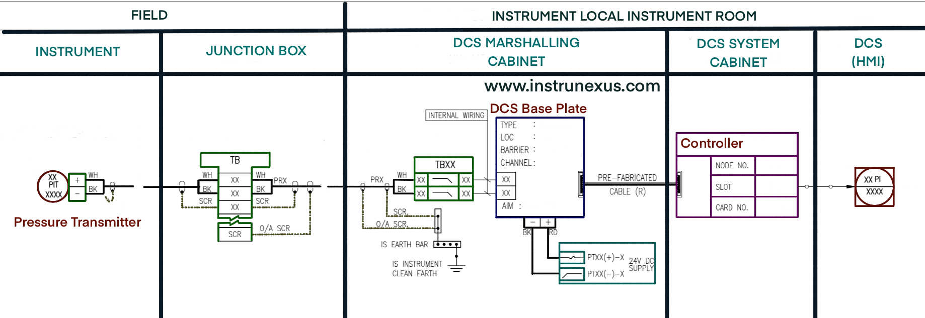
Purpose and Traceability
This diagram shows the signal continuity from the field instrument sensor, through any junction boxes or safety barriers, to the terminal block within the control system cabinet. Loop diagrams are paramount for Commissioning—serving as the roadmap for loop checks—and are the primary document utilized by technicians for troubleshooting instrumentation failures during operation and maintenance. Key details include wire numbers, cable numbers, intrinsic safety barrier details, and terminal identifications.
5.4 Cable Schedules and Cable Block Diagrams
Managing cable logistics is a major undertaking in any industrial project, addressed by systematic documentation.
Cable Schedules and MTO
The Cable Schedule is a detailed tabular list that manages the specific routing, sizing, and termination points of every cable. The list details the cable number, cable type, core size, exact termination locations (from/to points), and required length.
The schedule is essential for the construction phase, as it provides the basis for the Material Take-Off (MTO) for cable, cable tray, and associated infrastructure. The requirement for accurate cable length calculation necessitates the use of specialized I-CAD software that integrates with the 3D plant model (e.g., AutoCAD Plant 3D or AVEVA E&I). This integration prevents waste from over-ordering cable and ensures cable runs avoid physical clashes with piping and structural elements.
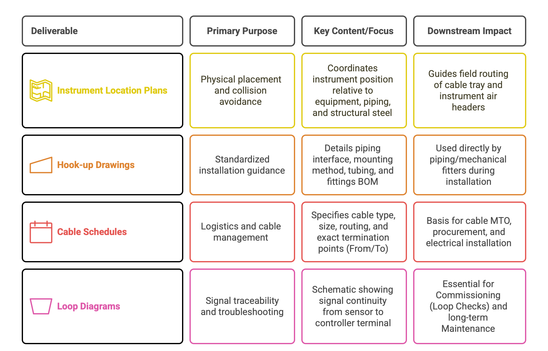
Table 3 summarizes the critical construction-focused deliverables.
Table 3: The Purpose and Necessity of C&I Installation Drawings
Section 6: Quality Assurance, Reviews, and Interdisciplinary Integration
The success of a capital project hinges on formal quality assurance gates and seamless coordination between engineering disciplines. C&I operates as a central integrating discipline, synthesizing data from Process Engineering and providing detailed requirements to Electrical, Piping, and Civil/Structural teams.
6.1 Critical Design Review Gates and Safety Compliance
Formal review gates are necessary to enforce quality, verify compliance with UFR, and manage risk.
HAZOP, LOPA, and SIL Integration
Safety reviews are undertaken in a progressively detailed manner throughout the design phases. The HAZOP study is performed once P&IDs are mature (IFH status) to identify deviations and hazards. If the risk is unacceptable, subsequent LOPA and SIL assessments determine the required level of functional safety for safety instrumented functions.
The C&I team must incorporate these safety findings, ensuring the final detailed design resolves all identified hazards. This involves updating datasheets to select appropriately certified instruments and refining the Control Narrative to incorporate necessary safety interlocks and shutdown criteria. The successful closure of this safety review process is formalized by issuing the documents for construction (IFC).
6.2 Interfacing with Process and Piping Engineering
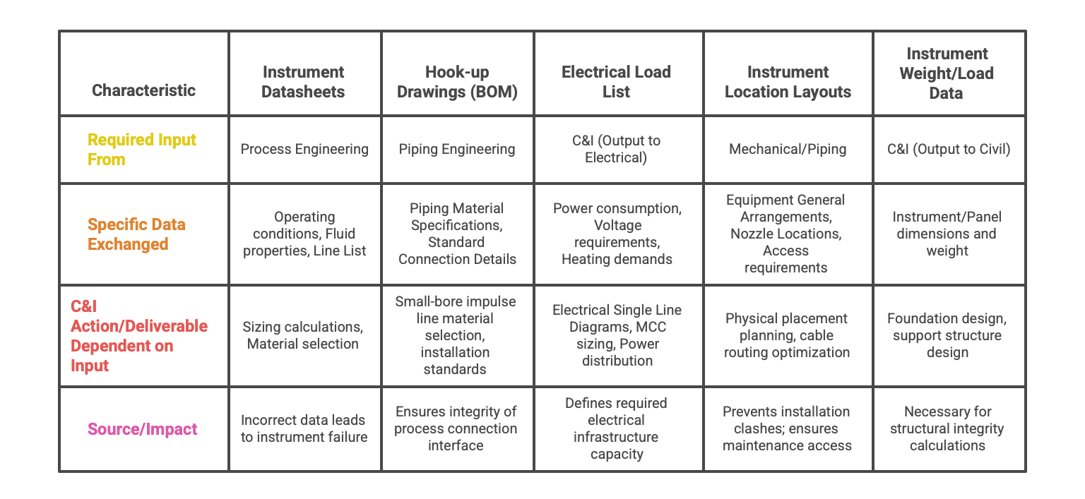
The C&I schedule is critically dependent on upstream data from Process Engineering. C&I uses Process Flow Diagrams (PFDs), the Heat and Material Balance (HMB), and the Line List to perform sizing calculations and select materials of construction for instruments.
In turn, C&I provides specific deliverables to the Piping department, primarily the Hook-up Drawings and associated BOMs. While P&IDs serve as the shared graphical document illustrating functional design, the Hook-up drawings provide the granular detail necessary for connecting instruments to the process lines, ensuring continuity in piping material specifications and integrity.
6.3 Interfacing with Electrical and Civil Engineering
C&I deliverables are a central mechanism for transferring requirements to the execution disciplines.
Outputs to Electrical Engineering
C&I systems represent a significant electrical load and require extensive power distribution and cabling infrastructure. C&I provides:
Electrical Load Consumption Lists: Detailed power requirements (VA/W) for control panels, instruments, safety barriers, and associated heating elements. This data is essential for Electrical Engineering to size Single-Line Diagrams (SLDs), Motor Control Centers (MCCs), and power distribution systems.
Cable Routing and Specifications: The Cable Schedules and cable block diagrams define the type, quantity, and required routing space (cable tray capacity) necessary for all control and communication wiring.
Panel Specifications: General arrangement and wiring details for all control panels and junction boxes.
Outputs to Civil/Structural Engineering
C&I contributes essential data for physical support design:
Weight and Dimension Data: Instrument and panel weights and dimensions are supplied to Civil/Structural engineers to calculate necessary dead loads for foundation design and support structure specifications (e.g., instrument racks).
Environmental Requirements: C&I specifications detail environmental parameters like seismic, soil, and wind conditions that must be accounted for in the structural design of instrument supports.
Furthermore, C&I is increasingly involved in providing Geotechnical Instrumentation systems (e.g., inclinometers, displacement sensors) used by Civil Engineers to monitor the health and stability of major infrastructure like dams, tunnels, and deep excavations. C&I designs the data acquisition and monitoring systems for these applications.
Table 2: Critical Interdisciplinary Data Exchange for C&I Engineering
6.4 Data Management and Document Control
Effective project management relies on rigorous document control and traceability. Documentation must be managed in real-time, especially during Phases 3 and 4, using specialized engineering data management software. This ensures traceability, allowing engineers to verify that the final installed configuration (As-Built) accurately reflects the original conceptual requirement (UFR) and all subsequent safety modifications (HAZOP/SIL actions). All documents, including P&IDs and preliminary configurations, require formal approval from the Project C&I Engineer and the client prior to advancing to formal Design Review gates.
Conclusions and Synthesis
The Instrumentation Design Engineering process is defined by a structured, phase-gated flow that mandates progressive maturity of technical scope and safety verification. The critical function of IDE is not merely to design individual components but to serve as the central information integrator for the entire capital project, linking process fluid properties, operational logic, electrical infrastructure, and structural requirements.
The successful execution of IDE is fundamentally reliant on:
Standardization and Safety Integration: Strict adherence to ISA and IEC standards, particularly ANSI/ISA 5.1 for documentation and ISA-84/IEC 61511 for functional safety. The resolution of design risks identified in HAZOP and SIL assessments must be demonstrably engineered into the final documentation before construction commences (IFC status).
Data Integrity and Traceability: Given the volume and interdependency of deliverables (Instrument Index, Datasheets, I/O lists), traditional manual methods are inadequate. Utilizing integrated, data-centric engineering tools is compulsory for maintaining accuracy across disciplines, ensuring procurement efficiency, and establishing reliable As-Built records for future operation and maintenance.
Interdisciplinary Coordination: The C&I deliverables, such as the Electrical Load List, Hook-up BOMs, and Instrument Location Layouts, are essential outputs that directly feed the design requirements of Electrical, Piping, and Civil Engineering disciplines, underscoring the role of C&I as a multidisciplinary hub in project execution.