
Comprehensive Guide: Thermal Mass Flowmeters (TMFM) Life-Cycle
Principle, Design, Selection, and Field Management for Critical Applications like Flare Gas.
Part 1: Working Principle and Fundamentals
Core Principle: Convective Heat Transfer
Thermal mass flowmeters (TMFMs) utilize two Resistance Temperature Detectors (RTDs) to measure the mass flow rate of a gas. Unlike volumetric meters, TMFMs are insensitive to changes in pressure and temperature, as they measure the cooling effect, which is directly related to the mass of the gas molecules flowing past the sensor. This method is critical for flare gas as it provides accurate data for environmental compliance reporting.
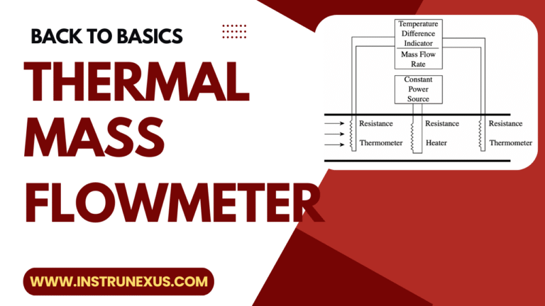
The Dual-Sensor System
Conceptual diagram of the RTD probes.
- RTD 1 (Reference): Measures the gas temperature (T_gas).
- RTD 2 (Heated): Maintained at a constant temperature (T_heated) above T_gas.
The Constant Temperature Differential (CTD) Method
The CTD method continuously adjusts the power (Q) supplied to the heated sensor to maintain a fixed temperature differential (Δ T = T_heated - T_gas). Heat loss via convection is directly proportional to the mass flow rate.
Where Q is the electrical power, 𝜌 V is the mass flow rate, and K is a constant (King's Law).
Part 2: Design and Selection Criteria
A. Engineering & Design Considerations
- Style & Size: Insertion (Probe) is standard for large flare lines (DN 200+). Inline models offer higher accuracy but are costly for large pipes.
- Materials: Wetted parts must withstand corrosive elements (H2S, moisture). Preferred alloys are 316L Stainless Steel or Hastelloy for enhanced chemical resistance.
- Certification: Mandatory ATEX/IECEx/FM hazardous area certification due to the explosive nature of flare gas.
- Pressure/Temp Rating: The meter's flange and thermowell must match the maximum process pressure and temperature ratings (including emergency relief scenarios).
B. Selection Criteria for Flare Gas
- Wide Turndown Ratio: TMFMs must achieve ultra-wide turndown (up to 1000:1) to accurately measure both low purge flow and high-velocity relief events.
- Gas Composition: Since flare gas composition varies, the meter must have multi-gas calibration tables or inputs for real-time calorific value correction to maintain accuracy.
- Low Flow Sensitivity: The meter must be sensitive enough to detect and measure purge flow accurately (0.01 to 0.1 ft/sec), which is critical for safety and emissions compliance.
- Accuracy & Repeatability: Typical accuracy requirement is 1-2% of reading. Repeatability is key for reliable environmental reporting.
Part 3: Testing, Storage, and Installation
Testing & Acceptance
- Factory Acceptance Test (FAT): Primary verification of calibration linearity against traceable standards using air or a substitute gas mix.
- Calibration Points: Check accuracy at minimum, intermediate, and maximum flow rates to confirm turndown performance.
- Documentation: Ensure the final calibration certificate (showing ΔT and power) and test reports are provided and validated.
Storage & Handling
- Protection: Store in original packaging. The sensor tip is highly sensitive; avoid physical shock, bending, or exposure to moisture/dust.
- Environment: Maintain a clean, dry area with controlled temperature and humidity (as per manufacturer's specifications).
- Pre-installation Check: Verify sensor integrity (e.g., RTD resistance values) before final installation.
Installation
- Straight Run: CRITICAL: Requires a minimum of 10-20 upstream and 5-10 downstream pipe diameters of straight, unobstructed run to ensure a stable, repeatable flow profile.
- Orientation: The probe sensor face MUST be perfectly aligned (parallel) with the direction of flow. Misalignment introduces significant error.
- Insertion Depth: Insertion length must be set precisely to place the sensor at the optimal velocity point, often the center-line or a fixed calculated radius.
Part 4: Commissioning and Maintenance
Commissioning Procedures
- Zero Flow Adjustment: With flow isolated, perform a "site zero" adjustment. The meter must read 0.00 to account for ambient heat loss unique to the installation.
- Loop Check: Verify the 4-20 mA or digital signal (e.g., Modbus) output into the control system (DCS/PLC) across the entire expected flow range.
- Configuration Verification: Check all software parameters: gas type/mix, pipe ID, units (SCFH - Standard Cubic Feet per Hour, Kg/hr - Kilograms per Hour, etc.), and alarm set points.
- Process Startup: Gradually introduce flow and monitor readings against expected values or comparative meters (if available).
Maintenance and Re-calibration
- Sensor Cleaning: Critical for flare service. Periodic inspection is needed. If no retraction tool is available, the line must be isolated. Remove and gently clean the sensor element if fouling (soot, oil mist) is visible.
- Drift Check: Regularly monitor the power required (mW) to maintain the constant ΔT. A significant change over time indicates sensor contamination or electronic drift.
- Re-calibration Frequency: Industry best practice suggests laboratory re-calibration every 1 to 3 years, especially for regulatory compliance applications like flaring.
- Spare Parts: Keep spare electronics and, if possible, a spare pre-calibrated probe head to minimize downtime during recalibration cycles.