
Interactive Explorer: Orifice Plate Flow Measurement
An interactive guide to the principles, components, and applications of differential pressure flow meters.
What is an Orifice Plate Flow Meter?
An orifice plate is a primary flow element used to measure the flow rate of a fluid (liquid or gas) in a pipe. It is essentially a thin plate with a precisely machined hole of a specific size. When this plate is installed in a pipeline, it creates a restriction, or constriction, to the fluid flow.
This constriction forces the fluid to accelerate as it passes through the hole, causing a drop in pressure across the plate. By measuring this pressure difference (known as differential pressure or ΔP), we can calculate the fluid's velocity and, consequently, its volumetric flow rate.
This method is one of the most common ways to measure flow in industrial applications due to its simplicity, reliability, and low cost. Its design, installation, and calculation are rigorously defined by international standards, most notably ISO 5167. This interactive guide will walk you through its operating principle, components, and the relationship between pressure and flow.
The Principle of Operation
The operation of an orifice plate is based on Bernoulli's principle, which states that for a flowing fluid, an increase in velocity occurs simultaneously with a decrease in pressure. When the fluid reaches the orifice plate, its cross-sectional area is reduced, forcing it to accelerate to maintain the flow rate. This increase in velocity (v_2) at the constriction (known as the "vena contracta," the point of minimum cross-section) results in a decrease in pressure (P_2) compared to the upstream pressure (P_1).
Simplified Flow Diagram
Fluid is forced through the orifice, accelerating and causing a pressure drop (ΔP = P_1 - P_2) at the vena contracta.
A differential pressure (DP) transmitter is connected to pressure taps upstream (P_1) and downstream (P_2) of the plate to measure this pressure drop. The flow rate (Q) is not linear but is proportional to the square root of this differential pressure:
Q ∝ ΔP
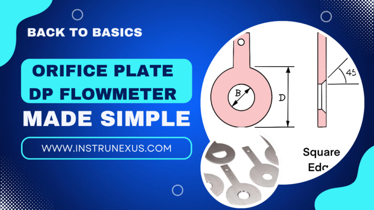
The precise calculation, as defined by ISO 5167, is more complex and involves a discharge coefficient (C), the fluid density (ρ), and the Beta Ratio (β). The Beta Ratio is the ratio of the orifice diameter (d) to the internal pipe diameter (D):
β = d / D
The choice of β is a critical design trade-off. A typical range is between 0.2 and 0.75. The table below outlines the implications of different beta ratios.
| Beta Ratio (β) | Restriction | ΔP Generated | Permanent Pressure Loss | Measurement Uncertainty |
|---|---|---|---|---|
| Low (e.g., 0.2 - 0.4) | High Restriction | High (Easy to measure) | High (High energy cost) | Low (Good accuracy) |
| High (e.g., 0.6 - 0.75) | Low Restriction | Low (Harder to measure) | Low (Low energy cost) | High (More uncertainty) |
The chart below visualizes the pressure change as the fluid passes through the pipe. You can see the initial pressure (P_1), the sharp drop at the orifice to P_2, and the partial pressure recovery downstream. A significant portion of this pressure drop is permanent, representing energy loss in the system.
Components & Types
While the concept is simple, the specific design of the orifice plate and the placement of the pressure taps are critical for accurate measurement. These components are standardized to ensure consistent and predictable results.
Concentric Plate
The most common type. The orifice is a sharp-edged, circular hole located in the center of the plate. It is ideal for clean, single-phase fluids (liquids and gases).
Eccentric Plate
The hole is offset from the center, typically tangent to the bottom of the pipe. This design allows solids or entrained liquids (in gas flow) to pass through, preventing buildup.
Segmental Plate
The orifice is a segment-shaped hole, also typically at the bottom of the pipe. It's used for slurries or fluids with a high concentration of solids, providing a clear path for debris.
Pressure Tap Locations
The location of the pressure taps is critical and strictly defined by standards like ISO 5167 to ensure a predictable discharge coefficient. Common types include:
- Flange Taps: The most common in North America. Taps are drilled 1 inch (25.4mm) upstream and 1 inch downstream from the plate faces.
- Vena Contracta Taps: Taps are located 1 pipe diameter upstream and at the point of minimum pressure downstream (the vena contracta), which varies with the β-ratio.
- Corner Taps: Common in Europe. Taps are drilled directly into the corner where the plate meets the pipe wall.
Interactive Relationship: ΔP vs. Flow
The most important concept to understand is the non-linear relationship between differential pressure (Δp) and flow rate (Q). Because Q is proportional to the square root of ΔP, a small change in flow at the low end of the scale produces a tiny change in ΔP, while the same change in flow at the high end produces a much larger change in ΔP.
Use the slider below to adjust the differential pressure and observe the corresponding flow rate. The chart plots this square-root relationship and will highlight your current position on the curve.
Move the slider from 0% to 100%
Advantages & Disadvantages
Orifice plates remain widely used, but they are not the best solution for every application. Understanding their trade-offs is key to proper selection.
Advantages
- ✓ Low Cost: Simple construction makes them inexpensive to manufacture and install compared to other meters.
- ✓ No Moving Parts: High reliability and low maintenance requirements.
- ✓ Well-Understood & Standardized: Performance is highly predictable and covered by international standards, primarily ISO 5167.
- ✓ Versatile: Can be used for most clean liquids, gases, and steam at various temperatures and pressures.
Disadvantages
- ✗ High Permanent Pressure Loss: The turbulence created causes significant, unrecoverable pressure loss, leading to higher energy (pumping) costs.
- ✗ Limited Range (Turndown): The square-root relationship limits accuracy over a wide flow range. Typical turndown is 3:1 to 4:1.
- ✗ Strict Installation Requirements: Requires long, straight, undisturbed runs of pipe upstream and downstream.
- ✗ Wear and Tear: The sharp edge of the orifice can erode over time, especially with abrasive fluids, affecting accuracy.
- ✗ Susceptible to Plugging: The sharp edge and small hole can trap solids or slurries, leading to inaccurate readings (unless eccentric/segmental plates are used).
This is to ensure a fully developed, swirl-free flow profile reaches the plate. As per ISO 5167, this can require 20 to 50 pipe diameters (D) of straight pipe upstream and 5 to 10 D downstream, depending on the β-ratio and upstream disturbances (like valves or elbows). This is often the biggest practical limitation.
Excelente información