
Case Study: Implementation of the Functional Safety Life Cycle in Oil & Gas
Project: High-Pressure Separator Gas Blowby Protection (SIF-V101-02)
Standard Reference: IEC 61511 Ed. 2 / IEC 61508
Sector: Upstream Oil & Gas / Offshore Processing
Subject: From Hazard Identification to Operations (A Cradle-to-Grave Analysis)
Executive Summary
This report provides an in-depth analysis of the Functional Safety Life Cycle applied to a critical process node in an offshore oil and gas production facility. The subject of this study is High-Pressure (HP) Production Separator V-101. The specific hazard analyzed is “Gas Blowby,” a scenario where the liquid level seal is lost, allowing high-pressure gas to flow into the downstream Low-Pressure (LP) separator, creating an immediate risk of vessel rupture, explosion, and multiple fatalities.
The report demonstrates the rigorous application of IEC 61511, detailing the qualitative risk assessment (HAZOP), the semi-quantitative allocation (LOPA), the engineering design of the Safety Instrumented System (SIS), SIL verification calculations, and the procedural requirements for proof testing.
1. Introduction and System Description
1.1 The Importance of the Safety Life Cycle
In the hydrocarbon processing industries, safety is not merely a practice but a system engineering discipline. The IEC 61511 standard outlines the “Safety Life Cycle,” a circular workflow designed to ensure that risks are identified and mitigated to a tolerable level. This case study illustrates that safety is not achieved by simply buying “SIL-rated” equipment; it is achieved through the disciplined execution of analysis, design, verification, and maintenance.
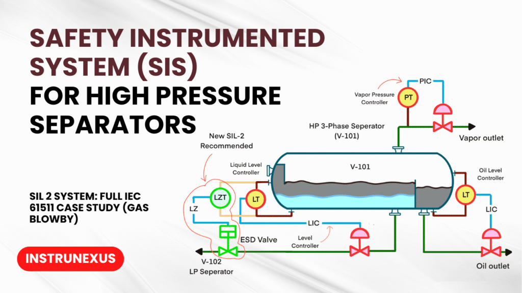
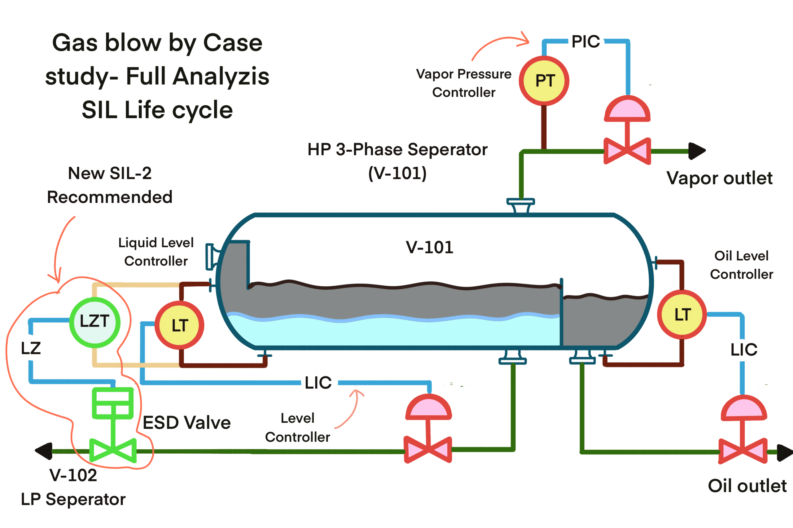
1.2 Process Description: The Three-Phase Separator (V-101)
The node under study is a First Stage Three-Phase Separator (V-101).
Function: Separates crude oil, associated gas, and produced water arriving from the wellheads.
Operating Pressure: 45 barg (High Pressure).
Downstream Process: The oil outlet feeds into the Second Stage Separator (V-102).
V-102 Design Pressure: 10 barg (Low Pressure).
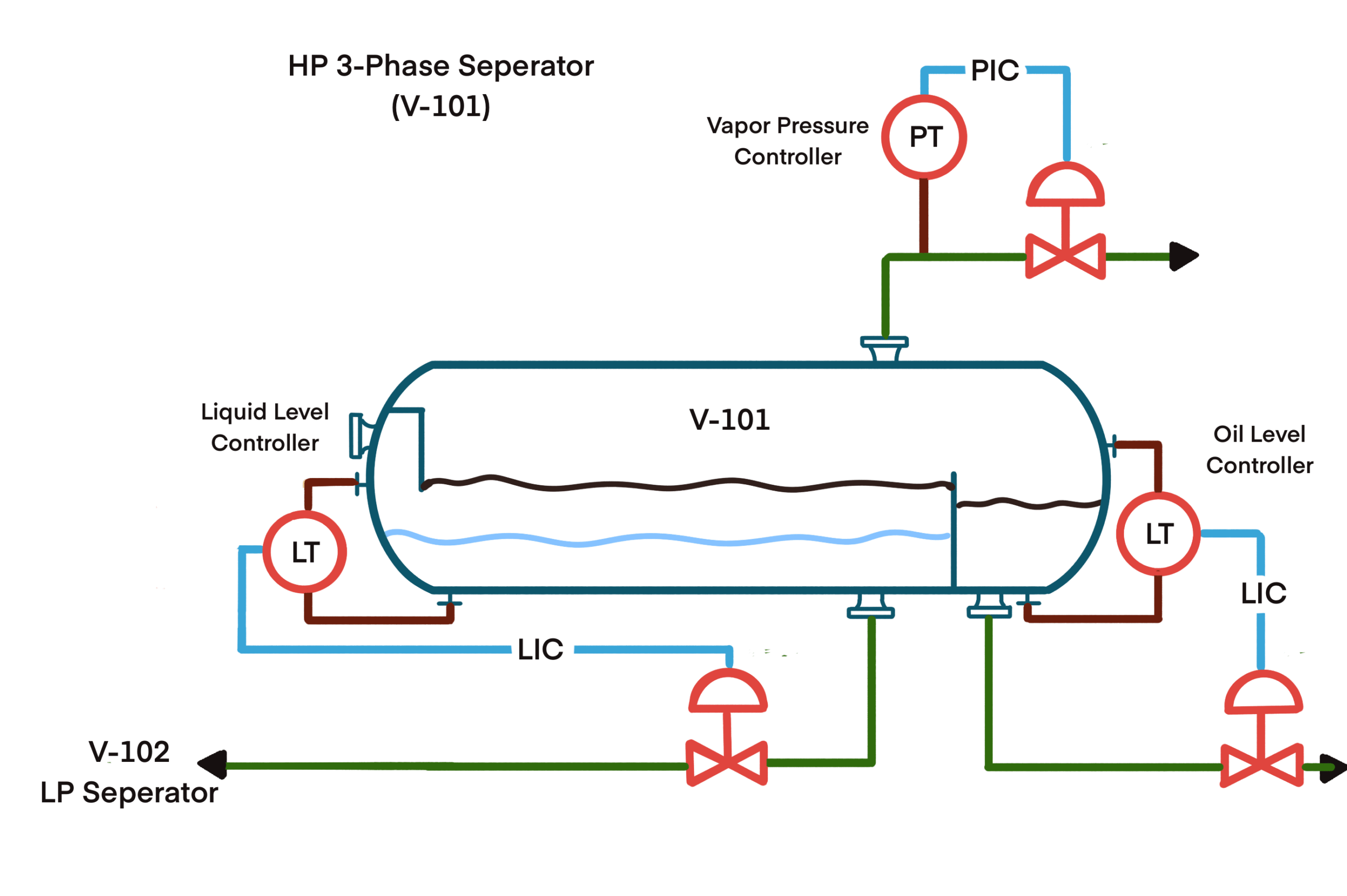
1.3 The Hazard Scenario
Under normal operation, a liquid level is maintained in V-101 by a Basic Process Control System (BPCS) regulating a Level Control Valve (LCV). This liquid acts as a seal. If the level control fails and the LCV remains open, the liquid inventory will drain completely. Once the liquid is gone, high-pressure gas (45 barg) will flow through the liquid line into the V-102 vessel (rated for 10 barg).
This phenomenon is known as “Gas Blowby.” The inflow of high-pressure gas can pressurize V-102 far faster than its Pressure Safety Valve (PSV) can relieve, leading to catastrophic vessel rupture.
2. Phase 1: Hazard and Operability Study (HAZOP)
The first step in the life cycle is the qualitative identification of hazards. A multi-disciplinary team (Operations, Process, Instrumentation, Safety) convened to analyze the V-101 node.
2.1 HAZOP Worksheet Extract
Node | Parameter | Deviation | Cause | Consequence | Safeguards (Existing) | Recommendations |
|---|---|---|---|---|---|---|
1. Oil Outlet Line | Level | Lower | 1. Level Control Valve (LCV) fails Open. | Global Consequence: Loss of liquid seal leading to Gas Blowby to V-102. Impact: Overpressure of V-102 beyond bursting limit. Rupture results in massive loss of containment (LOHC), vapor cloud explosion, and jet fire. Severity: Category 5 (Catastrophic – Potential Multiple Fatalities). | 1. Pressure Safety Valve (PSV) on V-102. (Note: Engineering check required to see if PSV is sized for blowby case). | 1. Verify V-102 PSV sizing for gas blowby case. 2. If PSV is insufficient, a SIL-rated instrumented function is required. |
2.2 HAZOP Conclusion
The engineering verification confirmed that the downstream PSV on V-102 was sized for fire case and blocked outlet, but not for full gas blowby from the HP separator. The volume of expanding gas would overwhelm the relief valve. Therefore, the mechanical safeguard is insufficient. The hazard must be carried forward to Layer of Protection Analysis (LOPA) to determine the necessary risk reduction.
3. Phase 2: Layer of Protection Analysis (LOPA)
LOPA is a semi-quantitative tool used to determine the required Safety Integrity Level (SIL) by analyzing the gap between the unmitigated risk and the corporate Tolerable Risk Frequency (TRF).
3.1 Establishing Criteria
Corporate Tolerable Risk Frequency (TRF): 1.0 X 10^-5 per year (1 in 100,000 years) for scenarios involving potential fatalities.
Target: The frequency of the mitigated event must be less than the TRF.
3.2 The LOPA Calculation
Step A: Determine Initiating Event Frequency (IEF) The primary cause is the failure of the BPCS level loop.
Generic failure rate for a control loop: 1.0 X 10^-1 per year (once every 10 years).
IEF = 0.1 / year.
Step B: Determine Consequence Severity
Explosion on an offshore platform implies a high probability of personnel presence.
Severity: Catastrophic.
Step C: Identify Independent Protection Layers (IPLs) To be an IPL, a safeguard must be Specific, Independent, Dependable, and Auditable.
Downstream PSV: Disqualified (Undersized for this specific case). Credit: 0.
Operator Response to Alarm: The operator would receive a “Low Level” alarm. However, gas blowby can occur in minutes. The stress level is high.
Credit: Standard LOPA credit for a busy control room is 0.1 (Risk Reduction Factor of 10).
Probability of Failure on Demand (PFD): 1.0 X 10^-1.
Process Design (Piping Rating): The downstream piping is not fully rated to HP specs. Credit: 0.
Step D: Calculate Intermediate Frequency
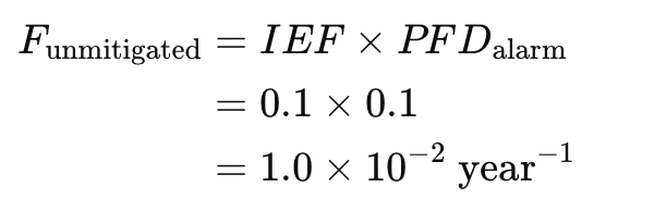
Step E: The Gap Analysis
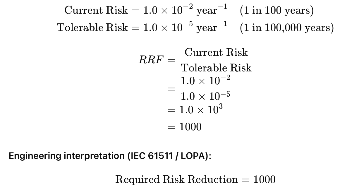
3.3 SIL Allocation Result
An RRF of 1000 corresponds to the boundary between SIL 2 and SIL 3.
SIL 1: RRF 10 – 100
SIL 2: RRF 100 – 1000
SIL 3: RRF 1000 – 10,000
Given the RRF is exactly 1000, and to add a margin of safety/robustness, the team allocates a SIL 3 requirement, or a high-integrity SIL 2 (RRF > 1000) if additional minor IPLs (like occupancy factors) are considered.
Decision for Case Study: We will target SIL 2 (RRF > 100) but with a high reliability target, utilizing a 1oo1 final element architecture with strict proof testing, or 1oo2 if needed. For the purpose of this analysis, we assume an Occupancy Factor of 0.1 (personnel are not always at the vessel), reducing the required RRF to 100. Final Target: SIL 2.
4. Phase 3: Safety Requirement Specification (SRS)
The SRS is the most critical document in the lifecycle. It translates the math of LOPA into engineering requirements. If the SRS is vague, the design will fail.
SIF Tag: SIF-V101-02 (Low Liquid Level Trip)
4.1 Functional Requirements
Safe State: Close the liquid Outlet Emergency Shutdown Valve (ESDV-101) and Close the Inlet SDV (SDV-100) to stop inflow.
Trip Point: 15% Level (Low-Low).
Sensing: Must detect liquid level interface.
Reset: Manual reset required from the Human Machine Interface (HMI) after field verification.
4.2 Integrity Requirements
Target SIL: SIL 2.
Mode of Operation: Low Demand Mode (Demand frequency < 1/year).
5. Phase 4: SIS Conceptual Design
To meet SIL 2, the architecture must be chosen carefully regarding Hardware Fault Tolerance (HFT), Safe Failure Fraction (SFF), and Systematic Capability (SC). The design utilizes a combination of IEC 61508 Route 1H (Hardware concepts) and Route 2S (Systematic capability).
5.1 Subsystem A: Sensors
Technology: Guided Wave Radar (GWR) – Smart Instrument (Type B Device).
Selected Architecture: 2oo3 (Two-out-of-Three) Voting.
Rationalization & Architecture Analysis:
Safety vs. Availability:
1oo2 (Safety Optimized): Extremely safe, but if one sensor fails “safe” (false low level), the plant trips. High spurious trip rate.
2oo2 (Availability Optimized): High availability, but if one sensor fails “dangerously” (frozen), the system fails.
2oo3 (Optimized): The “Goldilocks” configuration. It allows for one dangerous failure (still votes 1oo2) and one safe failure (still votes 2oo2) without losing safety or production.
Hardware Fault Tolerance (HFT): The 2oo3 configuration provides an HFT of 1. It can tolerate one hardware fault and still perform the safety function.
Safe Failure Fraction (SFF): Vendor data for the selected GWR indicates an SFF of 92% (Failures are largely detected by internal diagnostics).
Systematic Capability (SC): The selected device is certified SC 3 (SIL 3 Capable) by an accredited body (e.g., TÜV or Exida), satisfying the SIL 2 requirement.
5.2 Subsystem B: Logic Solver
Technology: Certified Safety PLC (Type B Device).
Selected Architecture: 1oo1 (Simplex) Safety Logic Solver.
Rationalization & Architecture Analysis:
Why 1oo1? Modern certified safety PLCs utilize internal redundancy (e.g., “1oo2D” – One-out-of-Two with Diagnostics on a single channel) or “Lockstep” processors. To the external user, it appears as a single module (1oo1), but internally it has high diagnostic coverage.
Hardware Fault Tolerance (HFT): HFT = 0.
IEC 61508 Route 1H compliance: For a Type B device to achieve SIL 2 with HFT=0, the SFF must be > 90%.
Safe Failure Fraction (SFF): > 99%. Due to intense internal diagnostics, almost all failures are detected and force the system to a safe state (de-energize).
Systematic Capability (SC): Certified SC 3.
5.3 Subsystem C: Final Elements
This is typically the weakest link and the most difficult to justify.
Valve: High-performance Ball Valve with metal seating (Type A Device – Simple Mechanical).
Actuator: Spring-Return Pneumatic (Type A Device).
Selected Architecture: 1oo1 (Single ESD Valve).
Rationalization & Architecture Analysis:
Cost vs. Risk: A second series valve (1oo2) doubles the cost and pressure drop. A single valve is acceptable if the reliability data supports it.
Hardware Fault Tolerance (HFT): HFT = 0.
IEC 61508 Compliance (The Challenge):
Route 1H: For a Type A device (valve) to meet SIL 2 with HFT=0, it requires an SFF > 60%. Standard valves often have SFF < 60% (most failures are dangerous stuck-shut).
Solution (Route 2H): This design utilizes Route 2H (Proven-in-Use). This allows HFT=0 for SIL 2 based on high-quality field failure data reliability, rather than SFF tables. The “Prior Use” certificate for this specific valve model in similar crude oil service demonstrates a reliability of 95% confidence.
Systematic Capability (SC): The valve vendor has provided an SC 2 certificate, which is sufficient for this SIL 2 function.
6. Phase 5: SIL Verification (Reliability Analysis)
We must now mathematically prove the design meets SIL 2 (PFDavg between 10^-2 and 10^-3) and satisfies architectural constraints.
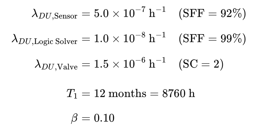
Data Inputs (Route 2H validated data):
6.1 Calculation: Sensors (2oo3)
Using simplified PFD approximation equations:
![]()
(Including Beta factor and geometric corrections, the simplified result is approximately 3.0 X 10^-4).
6.2 Calculation: Logic Solver
Certified safety PLCs usually have negligible PFD compared to field devices.
![]()
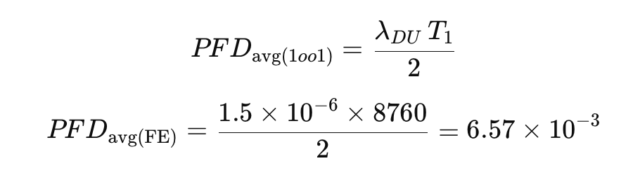
6.3 Calculation: Final Element (1oo1)
6.4 Total SIF PFD Calculation
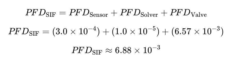
6.5 Verification Result
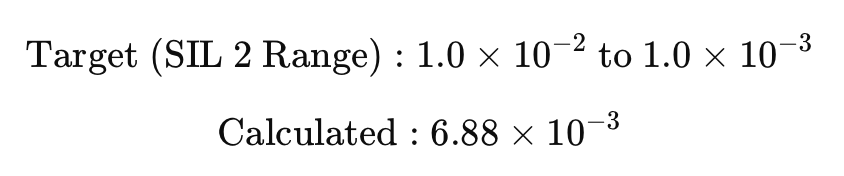
Conclusion: The design MEETS SIL 2.
Note: The final element contributes 95% of the risk. If the proof test interval is extended to 2 years, the calculation might fail, requiring a 1oo2 valve arrangement.
7. Phase 6: Installation and Commissioning
Safety is often compromised during installation due to poor workmanship or deviation from design.
7.1 Installation Constraints
Impulse Lines: The GWR probes must be installed directly on the vessel or in bridles with specific diameter requirements to prevent clogging (wax/asphaltenes).
Wiring: SIS wiring must be segregated from BPCS wiring to prevent electromagnetic interference (EMI) and common cause failures (e.g., a cable tray fire taking out both control and safety systems).
Color Coding: All SIS junction boxes and cables are painted/jacketed Red or Orange to distinguish them as critical safety systems.
7.2 Site Acceptance Testing (SAT)
Before introducing hydrocarbons, a full functional validation is performed:
Sensor Injection: The level in the bridle is physically lowered (using water) to the trip point.
Logic Verification: Confirm the PLC logic state changes.
Valve Stroke: Confirm the ESDV closes within the specified time (SRS requirement: < 15 seconds).
Feedback: Confirm the limit switch position is reported correctly to the control room.
8. Phase 7: Operation and Maintenance (Proof Testing)
A SIL certificate is valid only if the equipment is maintained. The “Proof Test” detects dangerous undetected failures ($\lambda_{DU}$) that automatic diagnostics cannot see (e.g., a valve stuck due to corrosion).
8.1 The Proof Test Procedure (Every 12 Months)
The calculation in Phase 6 assumed a 12-month test interval. If operations skip this, the PFD increases, and the SIF degrades to SIL 1 or SIL 0.
Test Steps:
Bypass: Place the SIF in maintenance bypass (requires strict permit to work and continuous monitoring).
Full Stroke: The ESDV must be fully closed. Partial Stroke Testing (PST) is useful for diagnostics but does not constitute a full proof test as it doesn’t check seat leakage or full travel torque.
Visual Inspection: Check for air leaks in the actuator, corrosion on the stem, and loose wiring.
Leak Test: Verify the valve actually holds pressure (internal leak rate). A valve that closes but leaks does not prevent the gas blowby scenario.
Restore: Remove bypass and verify the system is healthy.
8.2 Common Challenges in Operations
Bypass Management: The most frequent cause of safety incidents is a safety loop left in bypass mode during production. Modern Safety PLCs track bypasses and generate alarms if they remain active too long.
Deferred Maintenance: Extending the testing interval from 1 year to 2 years without re-verification of the SIL calculation is a violation of IEC 61511.
9. Comprehensive Analysis and Challenges
9.1 The “Common Cause” Threat
In our 2oo3 sensor design, we assumed the sensors were independent. However, if all three GWR probes are calibrated incorrectly by the same technician, or if all three bridles plug with wax simultaneously due to process cold flow, this is a Common Cause Failure (CCF).
Mitigation: Use diverse technologies (e.g., 2 GWR and 1 Differential Pressure) or enforce strict procedural diversity in maintenance.
9.2 Cyber Security (IEC 62443)
Modern Safety PLCs are connected to the plant network. A cyber-attack could force the SIS into bypass or alter trip points.
Requirement: The SIS must be “air-gapped” or protected by strict zones and conduits. Read/Write access from the business network to the Safety PLC must be hardware-blocked.
9.3 The Cost of Safety
Implementing this single SIF involves capital expenditure (CapEx) for 3 sensors, a dedicated PLC card, and a high-spec valve, plus Operational expenditure (OpEx) for annual testing. However, the cost of the “Gas Blowby” event—loss of the V-102 vessel, production shutdown for months, and potential loss of life—dwarfs the SIS cost. The Safety Lifecycle provides the financial justification by quantifying the risk.
10. Conclusion
This case study of the V-101 High-Pressure Separator highlights that Functional Safety is a rigorous, data-driven engineering process.
HAZOP identified the specific gas blowby hazard.
LOPA quantified the risk gap and mandated a SIL 2 reduction.
SRS defined the timing and architectural constraints.
Design & Verification proved that a 2oo3 sensor / 1oo1 valve arrangement met the reliability targets.
Operations maintains that integrity through strict proof testing.
Failure at any stage breaks the chain of protection. If the LOPA is too optimistic, the target SIL is too low. If the proof testing is skipped, the hardware reliability degrades. Only by adhering to the full V-Model of IEC 61511 can the Oil & Gas industry operate high-pressure assets with an acceptable level of risk.
Very interesting case. Thanks for sharing.
The case study does not mention a review of upsizing the PSV in the LP separator. ASM, API and other overpressure protection standards require the PRD option to be examined first.
Strong and well-executed case study, thanks for sharing. It clearly demonstrates the full FSM lifecycle, from HAZOP and LOPA through SIL verification and operations, rather than focusing only on SIL calculations. The treatment of gas blowby, PSV disqualification as an IPL, and the safety vs. availability discussion around the 2oo3 architecture are particularly solid and insightful.