
Control Valve Sizing & Selection
Comprehensive Technical Interview Questions & Detailed Answers
I. Fundamentals & Flow Sizing (Cv)
The flow coefficient, Cv, is the universal imperial standard used to compare the flow capacity of valves. It was introduced to simplify the complex fluid dynamics involved in sizing.
- Definition: Cv is defined as the number of US gallons per minute (GPM) of water at 60°F that will flow through a valve with a pressure drop of exactly 1 psi across the valve.
- Purpose: It lumps all the geometric factors of the valve (flow area, friction, path shape) into a single constant.
- Basic Sizing Formula (Liquids):
Cv = Q × √(SG / ΔP)Where Q is flow rate (GPM), SG is specific gravity, and ΔP is pressure drop (psi).
While Cv is the US standard, other regions use different units. An engineer must be able to convert between them to avoid massive sizing errors.
- Cv (Imperial): Based on Gallons/min and PSI. Used in the USA and by most oil & gas majors.
- Kv (Metric): Defined as the flow of water in cubic meters per hour (m³/h) with a pressure drop of 1 bar.
Conversion: Cv ≈ 1.156 × Kv (Cv is slightly larger than Kv). - Av (SI): An older or academic scientific unit representing the "Equivalent Flow Area" in square meters (m²). It is rarely used in practical plant sizing today but appears in theoretical fluid dynamics.
Choked flow is a fluid dynamic condition where the velocity of the fluid at the valve's narrowest point (vena contracta) reaches its physical limit.
- The Limit: For liquids, this is limited by vaporization (flashing). For gases, this is limited by the speed of sound (Sonic Velocity or Mach 1).
- Sizing Implication: Once a valve chokes, lowering the downstream pressure ($P_2$) further will not increase the flow rate. The flow is "choked" or capped at that maximum value.
- Standard Equation Failure: If you use the standard sizing equation during choked flow, it will calculate a required Cv that is impossible to achieve. You must use specific "Choked Flow" equations (using factors like FL or xT).
A simple "flow rate" and "line size" are insufficient. You need a complete process datasheet containing:
- Fluid Properties: Chemical name, state (gas/liquid/steam), Specific Gravity (SG), Viscosity, Vapor Pressure (Pv), and Critical Pressure (Pc).
- Flow Conditions: Maximum flow (for sizing capacity), Normal flow (for control stability), and Minimum flow (for turndown analysis).
- Pressure Conditions: Inlet Pressure (P1) and Outlet Pressure (P2) specifically at the maximum, normal, and minimum flow rates. P1 usually drops as flow increases due to pipe friction.
- Temperature: Operating temperature is vital for material selection (body and soft goods) and affects fluid density.
Valve sizing is a compromise between capacity and control resolution.
- Max Flow: We typically size the valve to travel to 85-90% open at maximum flow. We do not want 100% because we need a "safety margin" for process upsets.
- Normal Flow: The valve should operate around 50-70% open during normal plant operation. This keeps the plug in the center of the seat, offering the best control stability and response.
- Min Flow: We check the valve opening at minimum flow. If it is below 10%, there is a risk of the plug hitting the seat (instability) or "wire drawing" (erosion of the seat caused by high velocity fluid squeezing through a tiny gap).
Rangeability is a measure of the valve's versatility—how wide is the gap between the biggest flow it can handle and the smallest flow it can control accurately.
- Definition: Rangeability = Maximum Controllable Flow / Minimum Controllable Flow.
- Context: A high rangeability is necessary if a plant starts up at very low rates but runs at very high rates.
- Typical Values:
• Globe Valves: 30:1 to 50:1.
• V-Notch Ball Valves: 100:1 to 300:1 (Excellent for wide flow ranges).
• Butterfly Valves: 20:1 to 30:1 (Poor low-flow control).
The standard Cv equation assumes turbulent flow (like water flowing quickly). However, when fluids are thick or slow, flow becomes "Laminar".
- The Correction: The Reynolds Number Factor (FR) is a correction applied to the Cv calculation.
- Application:
• Turbulent Flow (Water, Air): FR = 1.0 (No correction needed).
• Laminar Flow (Heavy Oil, Molasses): FR drops below 1.0 (e.g., 0.7).
• Impact: If FR is 0.7, you need a valve that is roughly 30% larger than what the basic water formula suggests to pass the viscous fluid.
Specific Gravity is the density ratio of the fluid compared to water (for liquids) or air (for gases).
- The Physics: Heavier fluids (High SG) possess more inertia and are harder to push through a restriction.
- Sizing Impact:
• SG > 1 (e.g., Slurries): You need a larger valve (Higher Cv) to pass the same flow rate compared to water.
• SG < 1 (e.g., Gasoline): You can use a smaller valve because the fluid flows more easily. - Formula Insight: Since Cv is proportional to √(1/SG), if SG increases, flow capacity decreases.
The Vena Contracta is a specific physical location inside the valve body, just downstream of the plug and seat restriction.
- Why it matters: As fluid passes the narrow seat, it accelerates. By the Bernoulli principle, as velocity increases, pressure decreases.
- The Critical Point: The Vena Contracta is the point of maximum velocity and minimum pressure.
- Damage Zone: This is where cavitation starts. If the pressure at the Vena Contracta drops below the liquid's vapor pressure, bubbles form.
Control valves are often smaller than the pipeline size (e.g., a 4-inch valve in a 6-inch pipe). This requires the installation of concentric reducers and expanders.
- The Problem: The reducers and expanders create their own pressure drop due to friction and turbulence. This means there is less pressure drop available for the valve itself to do its job.
- The Solution: The Piping Geometry Factor (FP) is a derating factor (always < 1.0). It reduces the effective Cv of the valve assembly to account for the losses in the pipe fittings. Ignoring FP can result in an undersized valve.
II. Valve Characteristics & Trim
This is the most common confusion in valve selection.
- Inherent Characteristic: This is how the valve behaves on a test bench in the factory. The manufacturer maintains a constant pressure drop across the valve while plotting Flow vs. Lift. It represents the valve's pure geometry.
- Installed Characteristic: This is how the valve behaves in the real world. In a real pipe, as the valve opens and flow increases, the pressure drop across the valve decreases (because pipe friction eats up the pressure).
- Goal: We select a specific Inherent curve (like Equal Percentage) to counteract system losses, hoping to achieve a linear Installed behavior for the control loop.
With Linear trim, the flow capacity increases at the same rate as the valve travel (e.g., 20% open = 20% Cv).
- Application: Select Linear trim when the pressure drop across the valve remains relatively constant regardless of flow rate.
- Common Scenarios:
• Liquid Level Control (where the pressure is determined by static head).
• Flow Control loops where the valve takes a very large pressure drop compared to the rest of the system (the valve dominates the system).
With EQ% trim, the valve opens slowly at first (fine control) and then opens aggressively near the end. A 10% increase in travel produces an equal percentage change in the existing flow.
- Application: Select EQ% when the pressure drop across the valve decreases as flow increases. This is the case in 90% of pumped systems with long piping.
- Why? As the valve opens, the pipe friction reduces the available pressure. The aggressive opening shape of the EQ% valve compensates for this pressure loss, making the loop appear linear to the controller.
Quick Opening trim provides maximum flow capacity with minimal travel. It might provide 90% of its full flow at just 30% lift.
- Application: This is almost exclusively used for On/Off service (Shutdown valves, Interlock valves).
- Throttling: It is terrible for control/throttling because the "gain" is too high at the start—a tiny movement causes a massive flow surge, leading to instability.
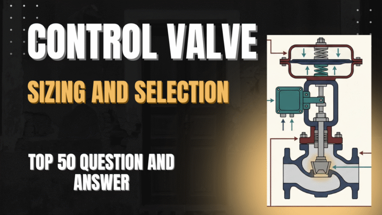
"Trim" refers to the internal parts of the valve that come into direct contact with the process fluid and regulate the flow. It is the heart of the valve.
- Plug (or Disc): The movable part that throttles flow.
- Seat Ring: The stationary part that the plug seals against to stop flow.
- Stem: The shaft connecting the actuator to the plug.
- Cage: A cylindrical guide surrounding the plug (in cage-guided valves) that determines flow characteristics and stability.
- Significance: The trim material is often higher grade (e.g., Stellite, 316SS) than the body material (Carbon Steel) to resist wear.
Cage-guided globe valves are the industry standard for severe service and general control.
- Stability: The plug is supported along its entire travel by the cage, eliminating vibration induced by high-velocity fluid.
- Flexibility: You can change the flow characteristic (from Linear to EQ%) simply by swapping the cage, without changing the plug or seat.
- Maintenance: They typically feature "top-entry" maintenance, allowing trim replacement without removing the valve body from the pipeline.
Reduced trim means putting a smaller sized internal seat/plug into a larger valve body.
- Example: A 4-inch valve body with 2-inch internals (trim).
- Scenario 1 (Piping limit): The pipe requires a 4-inch diameter for mechanical strength or velocity limits, but the flow rate is very low. Using reduced trim avoids installing pipe reducers.
- Scenario 2 (Future Expansion): A plant starts at 50% capacity. You install a full-size body with reduced trim. When production ramps up to 100% in 5 years, you simply swap the trim to full size rather than buying a new valve.
Stellite is a Cobalt-Chromium alloy (specifically Stellite 6) known for extreme hardness and heat resistance.
- Application: It is welded onto the seating surfaces of the plug and seat ring.
- Triggers for Selection:
• High Pressure Drop: ΔP > 150 psi (liquid) or ΔP > 300 psi (gas).
• Steam Service: To prevent "wire drawing" (steam cutting).
• Flashing/Erosion: Where abrasive fluids or flashing are present.
• Temperature: Operating temperatures > 600°F.
Anti-cavitation trim prevents the formation of vapor bubbles, rather than just withstanding them.
- Principle (Pressure Staging): Instead of taking the pressure drop in one giant step (which dips pressure below vapor pressure), this trim forces fluid through multiple small stages (like a cage with many small holes).
- Effect: The pressure drops gradually in steps (P1 → P_intermediate → P2). The pressure is never allowed to dip deep enough to cause vaporization, thus eliminating the root cause of cavitation.
Used for the most severe high-pressure drop applications (e.g., Compressor recycle valves, Let-down stations).
- Design: It uses a stack of discs with complex, laser-cut labyrinth channels.
- Mechanism: The fluid is forced to turn corners dozens of times. Each turn creates friction and reduces velocity (kinetic energy) while keeping the flow path controlled.
- Result: It effectively kills noise in gas applications and prevents cavitation in liquid applications by managing velocity ("Velocity Control").
III. Severe Service (Cavitation, Flashing, Noise)
Cavitation is a violent two-step process in liquid flows.
- Formation: As liquid squeezes through the valve, its velocity spikes and pressure plummets. If pressure drops below the fluid's Vapor Pressure ($P_v$), the liquid "boils" cold, forming vapor bubbles.
- Collapse: As the fluid enters the wider outlet piping, velocity slows and pressure recovers. The pressure rises back above $P_v$, causing the bubbles to implode instantly.
Damage: These implosions generate microscopic shockwaves and jets up to 100,000 psi, pitting and eating away hardened steel in minutes.
While Cavitation is a temporary phase change (Liquid → Vapor → Liquid), Flashing is permanent.
- Condition: In flashing, the downstream pressure ($P_2$) stays below the vapor pressure ($P_v$). The fluid enters as a liquid and leaves as a mixture of liquid and steam/vapor.
- The Danger: The bubbles do not collapse; instead, the huge expansion of volume (liquid to gas expansion) accelerates the flow to immense velocities.
- Mitigation: You cannot design a trim to stop flashing (it is dictated by process pressures). You must use hardened materials (Chrome-Moly) and larger outlet piping to handle the high-velocity volume.
Look at the Outlet Pressure ($P_2$) and the Vapor Pressure ($P_v$).
- Cavitation Scenario: $P_2 > P_v$. The pressure recovers to be a liquid again, so bubbles collapse inside the valve.
- Flashing Scenario: $P_2 < P_v$. The pressure never recovers enough to turn vapor back into liquid. The outlet flow is two-phase.
Sigma is a dimensionless number used by engineers to quantify how severe the cavitation risk is.
- Meaning: It compares the force keeping the liquid together (P1 - Pv) to the force trying to tear it apart (P1 - P2).
- Rules of Thumb:
• σ > 2.0: No cavitation (Safe).
• 1.0 < σ < 1.5: Incipient cavitation (Some noise, minor damage).
• σ < 1.0: Severe, choking cavitation. Requires special anti-cavitation trim.
Aerodynamic noise is the loud "screaming" or "roar" heard in gas or steam valves.
- Source: It is caused by the turbulence and shock waves generated when gas exceeds sonic velocity (Mach 1) inside the valve trim.
- Energy Conversion: A portion of the mechanical energy of the pressure drop is converted into acoustic energy.
- Solutions: Use "Low Noise" trim (drilled cages) that shifts the noise frequency to a higher pitch (ultrasonic) which is absorbed more easily by the pipe wall, or use inline diffusers/silencers downstream.
The Liquid Pressure Recovery Factor (FL) describes the internal geometry of the valve.
- High Recovery Valves (Low FL ~ 0.6): Butterfly and Ball valves. The flow is streamlined. Pressure drops heavily at the vena contracta but recovers significantly afterwards. Because the pressure dips so low internally, they are very prone to cavitation.
- Low Recovery Valves (High FL ~ 0.9): Globe valves. The tortuous path creates turbulence that prevents pressure from recovering much. Since the internal pressure dip is smaller, they are resistant to cavitation.
Sizing is not just about Cv; you must check the fluid velocity at the valve outlet.
- Liquids: Keep outlet velocity below 33 ft/s (10 m/s). Higher speeds cause body erosion and pipe vibration.
- Gases/Steam: Keep outlet velocity below 0.3 Mach for standard valves. For noise-attenuated valves, you might allow up to 0.5 Mach, but exceeding this generates noise levels > 85 dBA.
Viscous fluids (bitumen, heavy crude, polymers) resist flow and plug small openings.
- Valve Type: Avoid cage-guided valves (fluid will clog the cage holes). Use "flow-through" designs like Full Port Ball valves or Segmented V-Balls.
- Correction: Apply the Reynolds Number Factor ($F_R$) to size the valve larger than normal.
- Heating: Use steam jackets or electric trace heating on the valve body to lower the viscosity preventing solidification.
Sea water is highly corrosive due to chloride content, causing pitting and crevice corrosion.
- Standard Stainless (304/316): generally FAILS in warm sea water due to pitting.
- Preferred Materials:
• Duplex / Super Duplex SS (2205/2507): Excellent resistance and strength.
• Monel (Ni-Cu): Industry standard for marine environments.
• Nickel-Aluminum Bronze (NAB): Often used for butterfly valve discs in desalination.
This is a standard for materials used in environments containing Hydrogen Sulfide ($H_2S$), common in oil & gas.
- The Risk: $H_2S$ causes "Sulfide Stress Cracking" (SSC), where hard metals become brittle and shatter under stress.
- The Solution: Materials must be chemically resistant and, crucially, Heat Treated to a specific softness.
- Hardness Limit: Carbon steels and welds typically must be softer than 22 HRC (Rockwell C Hardness) to be NACE compliant.
IV. Actuation, Accessories & Leakage
Valves are not perfectly tight; they have allowable leakage rates when fully closed.
- Class II (0.5% capacity): Very loose. Used for double-ported balanced valves where tight shutoff isn't needed.
- Class III (0.1% capacity): Common for general control.
- Class IV (0.01% capacity): The industry standard for metal-seated Globe valves. Good enough for most process control.
- Class V (0.0005 ml/min per inch/psi): Required for severe service where leakage causes wire-drawing damage (e.g., high pressure steam). Requires lapped metal seats.
- Class VI (Bubble Tight): Requires soft seats (Teflon/PTFE). Used where zero leakage is permitted (e.g., fuel gas to burners).
- Spring-and-Diaphragm:
• Pros: Extremely reliable, low friction, inherently fail-safe (spring return), cost-effective.
• Cons: Limited force capability. Cannot handle extremely high pressure drops. - Piston Actuator:
• Pros: Can operate at high air pressures (80-100 psi) providing massive thrust for large valves. Long stroke capability.
• Cons: Higher friction (O-rings). Often requires a "trip tank" (air volume tank) to provide fail-safe action if not spring-loaded.
Bench Set refers to the specific pressure range required to stroke the actuator spring when the valve is on the workbench (no process pressure in the pipe).
- Example: A "3-15 psi" bench set means the stem starts moving at 3 psi and hits full travel at 15 psi.
- Why it matters: If you apply 3 psi and it doesn't move, the spring might be overtightened. The bench set confirms the actuator is healthy before installation.
The failure mode is decided by safety requirements (What should happen if the air supply line is cut?).
- Fail Closed (Air-to-Open - ATO): The spring forces the valve closed; air pressure pushes it open.
Use: Feed lines, Fuel lines. If control is lost, stop the flow to prevent danger. - Fail Open (Air-to-Close - ATC): The spring forces the valve open; air pressure pushes it closed.
Use: Cooling water lines, Blowdown valves. If control is lost, maximize cooling or relieve pressure to prevent explosion.
A positioner is a feedback controller mounted on the valve. It receives the 4-20mA signal and regulates air to the actuator to ensure the stem position matches the signal exactly.
Use a positioner if:
- You need high accuracy (Split-range control).
- The valve has high friction (Graphite packing) or is large/heavy.
- The actuator is Piston type (requires high pressure air, not just 3-15 psi).
- You need fast response speed (positioners boost volume).
Smart positioners contain a microprocessor replacing the mechanical linkages of old positioners.
- Auto-Calibration: They can calibrate zero and span in minutes with a button press.
- Diagnostics: They can detect "Stiction" (valve sticking), measure air consumption (leak detection), and log "Total Travel" (predictive maintenance).
- Configuration: Characteristics (Linear/EQ%) can be changed via software without changing physical trim.
These terms describe errors in valve movement.
- Dead Band (The "Slop"): The range of signal change that produces no movement in the valve. It is caused by mechanical looseness in the linkage. (e.g., Signal changes 12.0 → 12.1 mA, but valve doesn't move).
- Hysteresis (The "Memory"): The difference in position for the same signal depending on direction. (e.g., At 12mA, the valve is 50% open when opening, but 52% open when closing). It is caused by magnetic or elastic material properties and friction.
Packing seals the moving stem. The choice is a trade-off between friction and temperature.
- PTFE (Teflon):
• Pros: Extremely low friction (great control), chemically inert.
• Cons: Melts at > 400°F (200°C). Not fire-safe. - Graphite:
• Pros: Fire-safe, handles extreme temperatures (up to 1000°F+).
• Cons: Very high friction. Can cause "stick-slip" behavior (poor control) and requires larger actuators to overcome the drag.
A Volume Booster is a pneumatic relay used to speed up large valves.
- Problem: A standard positioner has small ports; it might take 30 seconds to fill a massive actuator for a 20-inch valve.
- Solution: The booster takes the signal from the positioner but draws high-volume air directly from the supply line to fill the actuator.
- Result: Reduces stroking time from 30 seconds to < 2 seconds (critical for Compressor Surge Control).
Handwheels allow manual operation during power failure.
- Side-Mounted: Geared mechanism on the side of the actuator. Easier to use (mechanical advantage) for large valves.
- Top-Mounted: A simple screw rod on top of the diaphragm casing. It acts as a "travel stop" (limit stop) as well. Cheaper, but harder to turn for high-force valves.
V. Installation & Troubleshooting
Bad piping geometry creates turbulence affecting control stability.
- Upstream: Provide at least 10 to 20 pipe diameters of straight pipe. This ensures the velocity profile is uniform entering the valve.
- Downstream: Provide 3 to 5 pipe diameters.
- Elbows: Never place an elbow immediately at the valve outlet. The high-velocity jet exiting the valve will hit the elbow wall, causing cavitation, noise, and rapid erosion.
A "Control Station" typically includes an upstream block valve, downstream block valve, and a manual bypass globe valve.
- Maintenance: If the control valve fails, you can close the block valves and open the bypass.
- Process Continuity: An operator can manually throttle the bypass valve to keep the plant running while the instrument tech repairs the control valve in the workshop.
Hunting is when the valve constantly oscillates open and closed around the setpoint, never settling.
Root Causes:
- Tuning: Controller Gain (P) is too high or Integral (I) is too fast.
- Oversizing: The valve is too large and operates near the seat (e.g., 5% open). Small movements cause huge flow changes.
- Stiction: High friction packing causes the valve to stick, then jump past the setpoint, then stick again.
Stiction is the enemy of precision control. It is the static friction that must be overcome to start the stem moving.
- Symptoms: The controller output changes smoothly, but the valve position looks like a staircase (steps). The process variable cycles in a "square wave" pattern.
- Fix: Loosen over-tightened packing, lubricate the stem, replace Graphite packing with PTFE (if temp allows), or install a high-performance Smart Positioner with "Stiction Compensation" algorithms.
Split ranging uses one controller output (0-100%) to drive two separate valves to extend rangeability.
- Scenario: A reactor needs heating (Steam) and Cooling (Water).
- Setup:
• Controller Output 0-50%: Opens the Cooling Valve (Full Open to Closed).
• Controller Output 50-100%: Opens the Heating Valve (Closed to Full Open). - Implementation: Calibrate Valve A positioner for 4-12 mA and Valve B positioner for 12-20 mA.
- Globe Valve:
• Best for: High pressure drops, severe service, high precision.
• Downside: Heavy, expensive, lower flow capacity per inch size. - Segmented V-Ball (Rotary Plug):
• Best for: High flow capacity, slurries (shearing action cuts fibers), high rangeability (100:1).
• Downside: Pressure recovery is lower (cavitation risk). - Butterfly:
• Best for: Large lines (> 6 inch), low pressure, utility water/air. Cheapest option.
• Downside: Poor control range (only linear between 20-60 degrees open). High cavitation risk.
ASME B16.34 defines Pressure-Temperature ratings.
- Concept: "Class 150" does not mean it is rated for 150 psi. It is a designation.
• At 100°F, a Carbon Steel Class 150 valve holds ~285 psi.
• At 100°F, a Carbon Steel Class 600 valve holds ~1480 psi. - Temperature Derating: As temperature rises, steel weakens. A Class 150 valve might hold 285 psi at room temp, but only 170 psi at 600°F. You must check the standard tables.
For Globe valves, the direction fluid enters relative to the plug matters.
- Flow-to-Open (Standard): Fluid enters under the plug, pushing it up (open).
Why? It is stable. If the stem breaks, flow pushes the plug open (usually safer). It helps the actuator open the valve. - Flow-to-Close: Fluid enters over the plug, pushing it down (closed).
Risk: "Bathtub Stopper Effect." As the plug gets close to the seat, the flow sucks it shut violently (slamming).
Use Case: Rare. Used for high-pressure erosive services or specific anti-cavitation trims where flow must go over the plug.
Sometimes, fully opening or fully closing during air failure is dangerous. You want the valve to stay exactly where it is.
- Accessory: An "Air Lock Valve" is installed on the actuator.
- Operation: It monitors the supply air pressure. If supply drops below a setpoint (e.g., 40 psi), the lock valve snaps shut, trapping the existing air volume inside the diaphragm casing. The valve freezes in its last position.
The Beta Ratio (β) is the ratio of Valve Trim Diameter (d) to Pipe Diameter (D).
- Noise implication: If you put a tiny valve in a huge pipe (Small β), the sudden expansion at the outlet creates massive turbulence and noise.
- Swaging: This refers to expanding the valve outlet. For high noise gas valves, we often use "Expanded Outlet" bodies (e.g., 4-inch inlet, 8-inch outlet) to control the expansion velocity and reduce noise levels.