A Deep Dive into Functional Safety: How IEC 61508 Governs Safety Instrumented Systems (SIS)
In the world of industrial processes, from chemical plants and oil refineries to power generation and manufacturing, the silent hum of machinery and the steady flow of materials are the sounds of productivity. But beneath this surface of controlled operation lies the potential for significant hazards. A runaway reaction, a vessel overpressure, or a critical equipment failure can have catastrophic consequences, endangering lives, devastating the environment, and leading to massive economic losses. In this high-stakes environment, ensuring safety isn’t just a priority; it’s a fundamental necessity. This is where the concept of functional safety and the robust framework of IEC 61508 come into play, providing a systematic and rigorous approach to protecting our industrial world.
This blog post will take a deep dive into the foundational international standard for functional safety, IEC 61508, and explore its critical application to Safety Instrumented Systems (SIS). We will journey through the core principles of this standard, dissect its comprehensive safety lifecycle, demystify Safety Integrity Levels (SILs), and examine the stringent requirements it places on the hardware and software that form the last line of defense against industrial disasters.
Understanding Functional Safety and the Role of IEC 61508
At its core, functional safety is the active monitoring of a process to detect a potentially dangerous condition and, upon detection, execute a pre-defined, controlled action to prevent a hazardous event or mitigate its consequences. It’s about ensuring that a safety system will perform its intended function correctly when called upon, or fail in a predictable and safe manner.
In a typical industrial facility, safety is achieved through multiple layers of protection, often visualized as an “onion skin” diagram. The inner layers consist of the basic process control system (BPCS), which manages the day-to-day operation of the plant, along with alarms and operator intervention. These are designed to keep the process within its normal operating parameters. However, if these layers fail, a more robust and independent layer of protection is required. This is the role of the Safety Instrumented System.
Block Diagram 1: Layers of Protection (LOP) “Onion Skin” Diagram
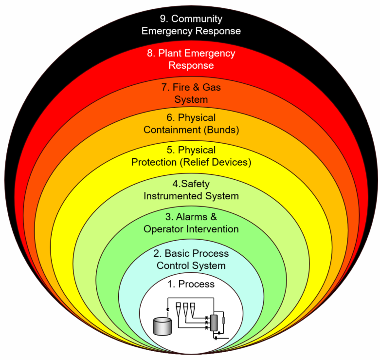
This simplified “onion skin” diagram illustrates the concept of Layers of Protection (LOP). Each layer is independent, and the SIS provides a critical level of defense when the inner layers, like the BPCS, are unable to maintain control.
IEC 61508, titled “Functional safety of electrical/electronic/programmable electronic safety-related systems,” serves as the foundational, or “umbrella,” standard for functional safety. It establishes a common framework and a set of comprehensive requirements for the entire lifecycle of safety systems that rely on electrical, electronic, and programmable electronic (E/E/PE) technologies. While IEC 61508 is a generic standard applicable to any industry, it has given rise to several sector-specific standards. For the process industry, the most important of these is IEC 61511, which adapts the principles of IEC 61508 to the specific needs and characteristics of this sector. For the purpose of this discussion, we will focus on the foundational principles laid out in IEC 61508, which are the bedrock upon which standards like IEC 61511 are built.
The Heart of the Standard: The IEC 61508 Safety Lifecycle
The cornerstone of IEC 61508 is the safety lifecycle. This is a structured, engineering process that defines all the necessary activities involved in the conception, design, implementation, operation, maintenance, and eventual decommissioning of a safety system. The primary goal of the safety lifecycle is to minimize the introduction of human error at any stage, which is a leading cause of safety system failures. By mandating a systematic and well-documented approach, the safety lifecycle ensures that safety is considered holistically and rigorously throughout the entire life of the system.
The safety lifecycle can be broadly divided into three main phases: Analysis, Realization, and Operation & Maintenance.
Block Diagram 2: The IEC 61508 Safety Lifecycle
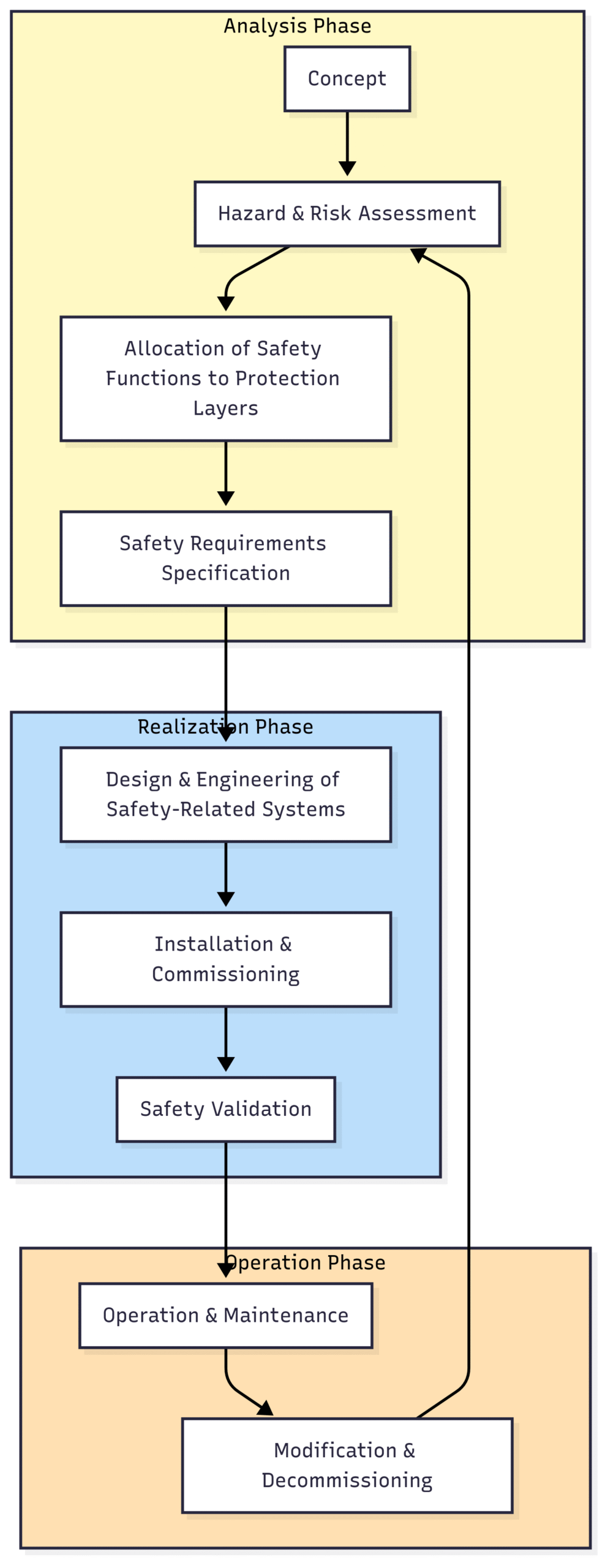
This flowchart provides a simplified representation of the IEC 61508 safety lifecycle, illustrating the logical progression from initial hazard analysis to eventual decommissioning, with a continuous loop for modifications.
1. Analysis Phase: This initial phase is all about understanding the risks and defining what the safety system needs to do.
Hazard and Risk Assessment: This is the starting point. Methodologies such as Hazard and Operability studies (HAZOP) or Layer of Protection Analysis (LOPA) are used to systematically identify potential hazards, their causes, and their consequences. The risk associated with each hazard is then evaluated based on its likelihood and severity.
Allocation of Safety Functions to Protection Layers: Based on the risk assessment, decisions are made on how to mitigate the identified risks. This involves determining if the existing protection layers (like the BPCS) are sufficient. If the residual risk is still unacceptably high, a specific Safety Instrumented Function (SIF) is allocated to an SIS to reduce the risk to a tolerable level.
Safety Requirements Specification (SRS): This is arguably the most critical document in the safety lifecycle. The SRS details everything the SIS needs to do. It specifies the required Safety Integrity Level (SIL) for each SIF, the functional requirements (e.g., “if the pressure in vessel V-101 exceeds 10 bar, then close valve XV-101 within 2 seconds”), and the integrity requirements (how reliably it must perform this function).
2. Realization (Design and Implementation) Phase: This phase turns the requirements defined in the SRS into a tangible, working system.
Design and Engineering of the SIS: This involves the detailed design of both the hardware and software components of the SIS. This includes selecting appropriate sensors, logic solvers (like safety PLCs), and final elements (such as valves and actuators), and designing the system architecture to meet the required SIL.
Installation, Commissioning, and Validation: The designed SIS is then installed in the plant and commissioned. Crucially, it undergoes a rigorous validation process to confirm that the installed system meets all the requirements laid out in the SRS. This is a “proof in practice” that the system performs as intended before it goes live.
3. Operation and Maintenance Phase: Once the SIS is operational, the lifecycle continues to ensure its integrity over its entire lifespan.
Operation and Maintenance Procedures: Clear procedures are established for the ongoing operation and maintenance of the SIS. This includes routine checks and ensuring that any bypasses or overrides of the safety system are strictly controlled.
Proof Testing: Since many dangerous failures of an SIS can remain undetected during normal operation (as the SIS may not be called into action for years), regular proof testing is essential. This involves periodically testing the entire SIF (from sensor to final element) to uncover any hidden failures. The frequency of these tests is a critical factor in maintaining the system’s SIL.
Modification and Decommissioning: Any changes to the SIS, no matter how small, must be carefully managed through a formal Management of Change process to ensure that the safety integrity is not compromised. Finally, at the end of its life, the system must be safely decommissioned.
Quantifying Safety: Safety Integrity Levels (SILs)
A central concept within IEC 61508 is the Safety Integrity Level (SIL). A SIL is a discrete level (from 1 to 4) used to specify the required level of risk reduction that a safety function must provide. The higher the SIL, the greater the required risk reduction, and consequently, the more stringent the requirements for the SIS.
The required SIL for a particular safety function is determined during the hazard and risk assessment phase. It is a direct measure of the difference between the existing process risk and the tolerable risk for that specific hazard.
Block Diagram 3: Risk Reduction and SIL
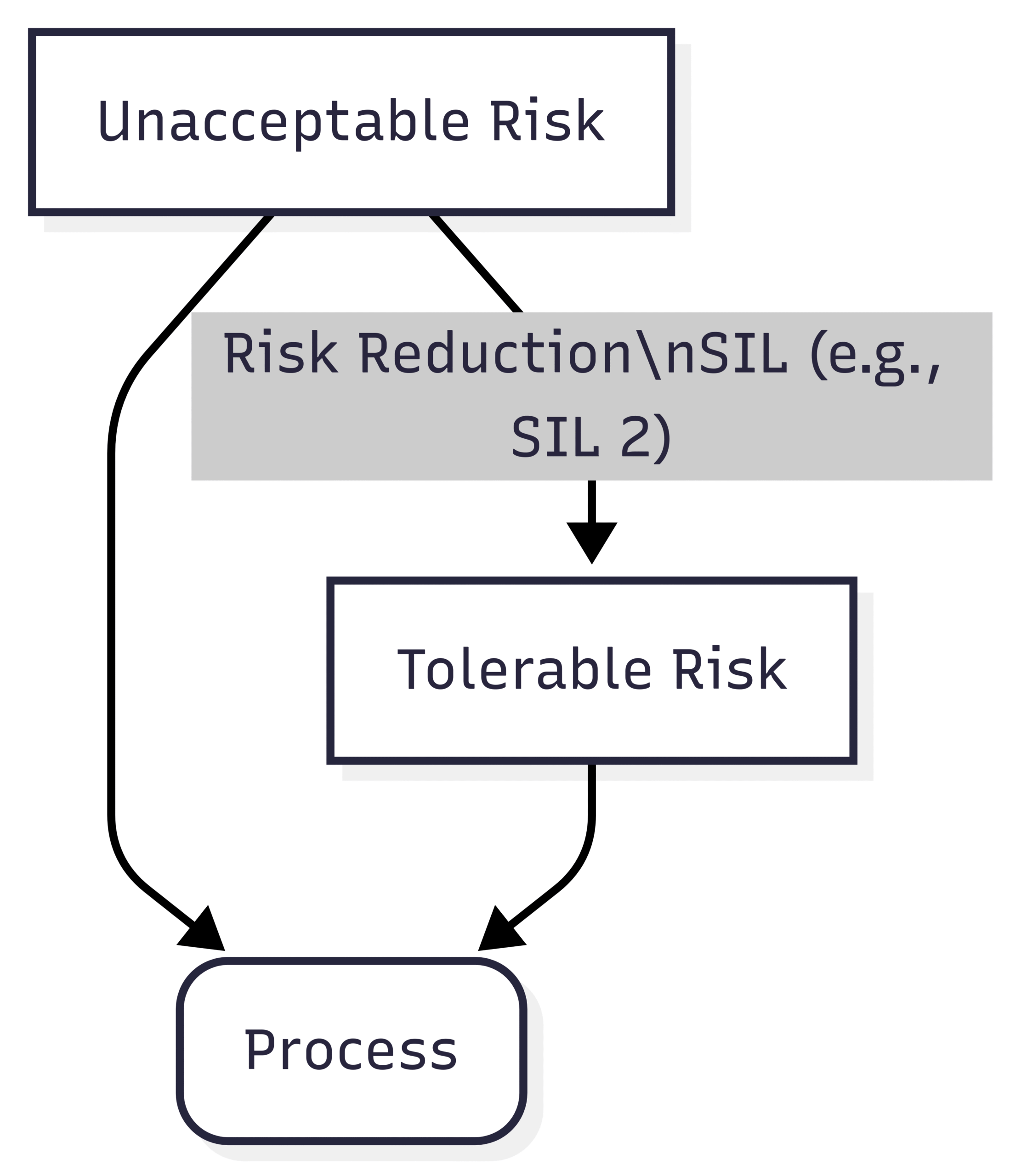
This conceptual diagram shows how a Safety Instrumented System (SIS) reduces the inherent risk of a process from an unacceptable level to a tolerable level. The amount of risk reduction required determines the necessary Safety Integrity Level (SIL).
SILs are quantified by two primary metrics, depending on the mode of operation of the safety system:
Probability of Failure on Demand (PFD): For safety systems that operate in “demand mode” (i.e., they only act when a dangerous condition occurs), the SIL is defined by the average probability that the system will fail to perform its function when required. This is the most common metric for SIS in the process industry.
Probability of Failure per Hour (PFH): For safety systems that operate in “continuous mode” (i.e., they are constantly working to maintain a safe state), the SIL is defined by the probability of a dangerous failure per hour.
The following table summarizes the SILs for systems operating in demand mode:
As the table shows, a SIL 3 system is required to be between 10 and 100 times more reliable than a SIL 1 system. SIL 4 applications are rare in the process industry and are typically associated with extreme hazards where the consequences of failure are immense, such as in the nuclear industry.
Building a Reliable SIS: Hardware and Software Requirements
Achieving and maintaining a specific SIL is not just a matter of calculation; it requires a disciplined approach to the design of both the hardware and software of the SIS. IEC 61508 lays out stringent requirements for both to ensure that the system’s integrity is built-in.
Block Diagram 4: A Typical SIS Architecture
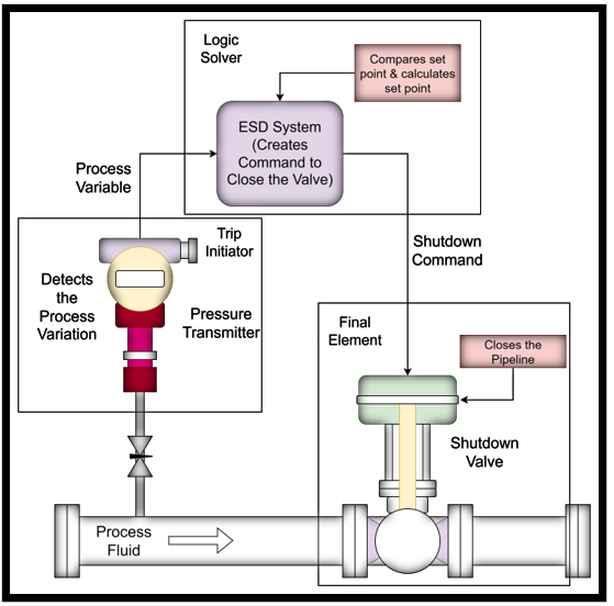
A typical Safety Instrumented System (SIF) consists of three key components: one or more sensors to detect a hazardous condition, a logic solver to process the information and make a decision, and one or more final elements to carry out the protective action.
Hardware Requirements:
To ensure hardware reliability, IEC 61508 imposes three key requirements:
Architectural Constraints (Hardware Fault Tolerance – HFT): This relates to the system’s ability to tolerate faults. For higher SILs, redundancy is often required. For example, a
1oo2(one-out-of-two) sensor architecture means that if one sensor fails, the other can still perform the safety function. A2oo3(two-out-of-three) voting arrangement provides even greater fault tolerance and availability. The standard specifies minimum HFT requirements based on the SIL and the type of component.Probability of Dangerous Failure (PFDavg): The calculated PFDavg for the entire safety function—summing the failure probabilities of the sensor, logic solver, and final element—must be within the range for the target SIL. This requires reliable failure rate data for all components, often obtained from manufacturer certifications or field studies.
Safe Failure Fraction (SFF): This metric represents the proportion of failures in a component that are either “safe” (the failure does not compromise the safety function) or are detected as “dangerous” by diagnostic features. IEC 61508 requires a higher SFF for higher SILs, driving the use of more intelligent devices with better self-diagnostic capabilities.
Software Requirements:
Unlike hardware, which can fail randomly, software failures are systematic—they are designed into the code from the beginning. A software bug will always be present until it is found and fixed. Therefore, the approach to ensuring software integrity is focused on avoiding the introduction of faults during the development process.
Systematic Integrity: IEC 61508 mandates a rigorous software development process, often referred to as a “software safety lifecycle,” that runs in parallel with the main hardware lifecycle.
Increasing Rigor: The level of rigor, the amount of testing, and the depth of verification and validation activities increase significantly with the SIL. For a SIL 3 system, the software development process is far more demanding than for a SIL 1 system.
Techniques and Measures: The standard recommends or requires various techniques to prevent software faults, such as structured design and coding standards, extensive peer reviews, and different levels of testing (module, integration, and validation). The goal is to build quality and safety into the software from the very beginning.
Conclusion
IEC 61508 provides an indispensable framework for managing functional safety in a world where our reliance on automated systems to prevent disasters is ever-increasing. Its application to Safety Instrumented Systems is not merely a matter of regulatory compliance; it is a fundamental pillar of responsible engineering practice. By mandating a comprehensive lifecycle approach, from the initial identification of hazards to the final decommissioning of a safety system, IEC 61508 drives a culture of safety that is systematic, verifiable, and robust.
The principles of SILs, the rigor of the safety lifecycle, and the detailed requirements for hardware and software all work in concert to ensure that when a process veers towards a hazardous state, the SIS will be ready and able to perform its critical protective function. In the complex and often unforgiving environment of industrial processes, adherence to IEC 61508 provides the structure and discipline needed to build a safer tomorrow, protecting lives, the environment, and the very infrastructure of our modern world.