A Step-by-Step Guide to the Functional Safety Lifecycle (IEC 61511)
In the high-stakes world of the process industry, ensuring the safety of personnel, the environment, and assets is not just a best practice; it’s a critical necessity. The International Electrotechnical Commission’s (IEC) 61511 standard provides a framework for achieving functional safety through the implementation of Safety Instrumented Systems (SIS). At the heart of this standard lies the functional safety lifecycle, a systematic, step-by-step approach to managing safety from conception to decommissioning. This comprehensive guide will walk you through each phase of the IEC 61511 lifecycle, complete with block diagrams to illustrate the journey towards a safer industrial process.
Understanding the Importance of a Lifecycle Approach
The functional safety lifecycle is not a mere checklist but a continuous improvement cycle designed to identify, control, and manage safety risks effectively. By following this structured approach, organizations can reduce the likelihood of catastrophic incidents, ensure regulatory compliance, and foster a strong safety culture. Each phase of the lifecycle is interconnected, with the outputs of one phase forming the inputs for the next, ensuring a cohesive and robust safety strategy.
Phase 1: Hazard and Risk Assessment
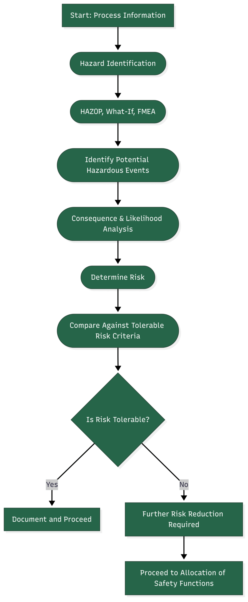
The journey into functional safety begins with a fundamental question: What can go wrong? The Hazard and Risk Assessment (HRA) phase is the cornerstone of the entire lifecycle, aiming to systematically identify potential hazards, analyze their causes and consequences, and evaluate the associated risks.
Key Activities:
Hazard Identification: Techniques like Hazard and Operability (HAZOP) studies, What-If analysis, and Failure Mode and Effects Analysis (FMEA) are employed to brainstorm potential deviation from the design intent that could lead to hazardous events.
Consequence and Likelihood Analysis: For each identified hazard, the severity of its potential consequences (e.g., harm to people, environmental damage, financial loss) and the likelihood of its occurrence are estimated.
Risk Evaluation: The identified risks are evaluated against the organization’s tolerable risk criteria. This helps in determining whether the existing safeguards are sufficient or if additional risk reduction measures are required.
Block Diagram: Hazard and Risk Assessment
Phase 2: Allocation of Safety Functions to Protection Layers
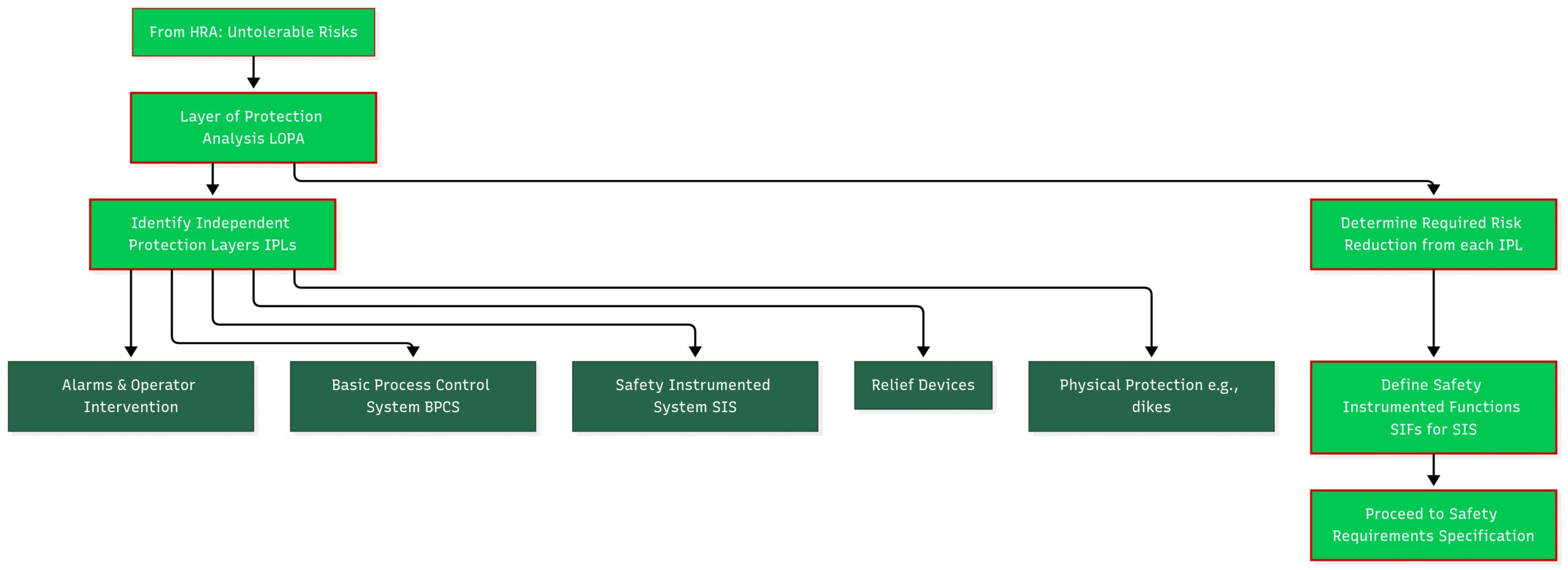
Once it’s determined that additional risk reduction is necessary, the next step is to decide how to achieve it. Modern process plants employ multiple independent protection layers (IPLs) to prevent or mitigate hazardous events. These layers can include the basic process control system (BPCS), alarms, relief devices, and, crucially, the Safety Instrumented System (SIS).
Key Activities:
Layer of Protection Analysis (LOPA): LOPA is a semi-quantitative tool used to determine the required risk reduction for a specific hazardous event and to allocate safety functions to different protection layers.
Defining Safety Instrumented Functions (SIFs): For the risks that will be managed by the SIS, specific Safety Instrumented Functions (SIFs) are defined. A SIF is a safety function with a specified Safety Integrity Level (SIL) which is necessary to achieve a tolerable risk level.
Block Diagram: Allocation of Safety Functions
Phase 3: Safety Requirements Specification (SRS)
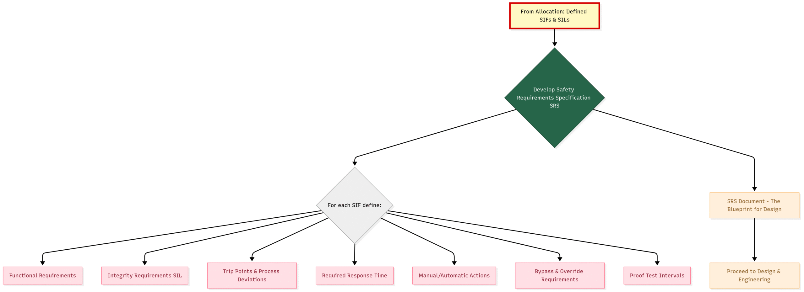
The Safety Requirements Specification (SRS) is arguably the most critical document in the functional safety lifecycle. It translates the “what” of the HRA and LOPA into the “how” for the design of the SIS. A well-defined SRS is clear, concise, and unambiguous, serving as the blueprint for the entire safety system.
Key Requirements Documented in the SRS:
A clear description of each SIF and its safety-critical action.
The required Safety Integrity Level (SIL) for each SIF.
The process conditions that will trigger the SIF.
The response time required for the SIF to bring the process to a safe state.
Requirements for manual shutdown, startup, and bypasses.
The expected demand rate on the SIF.
Proof test intervals for each SIF.
Block Diagram: Safety Requirements Specification
Phase 4: Design and Engineering of the SIS
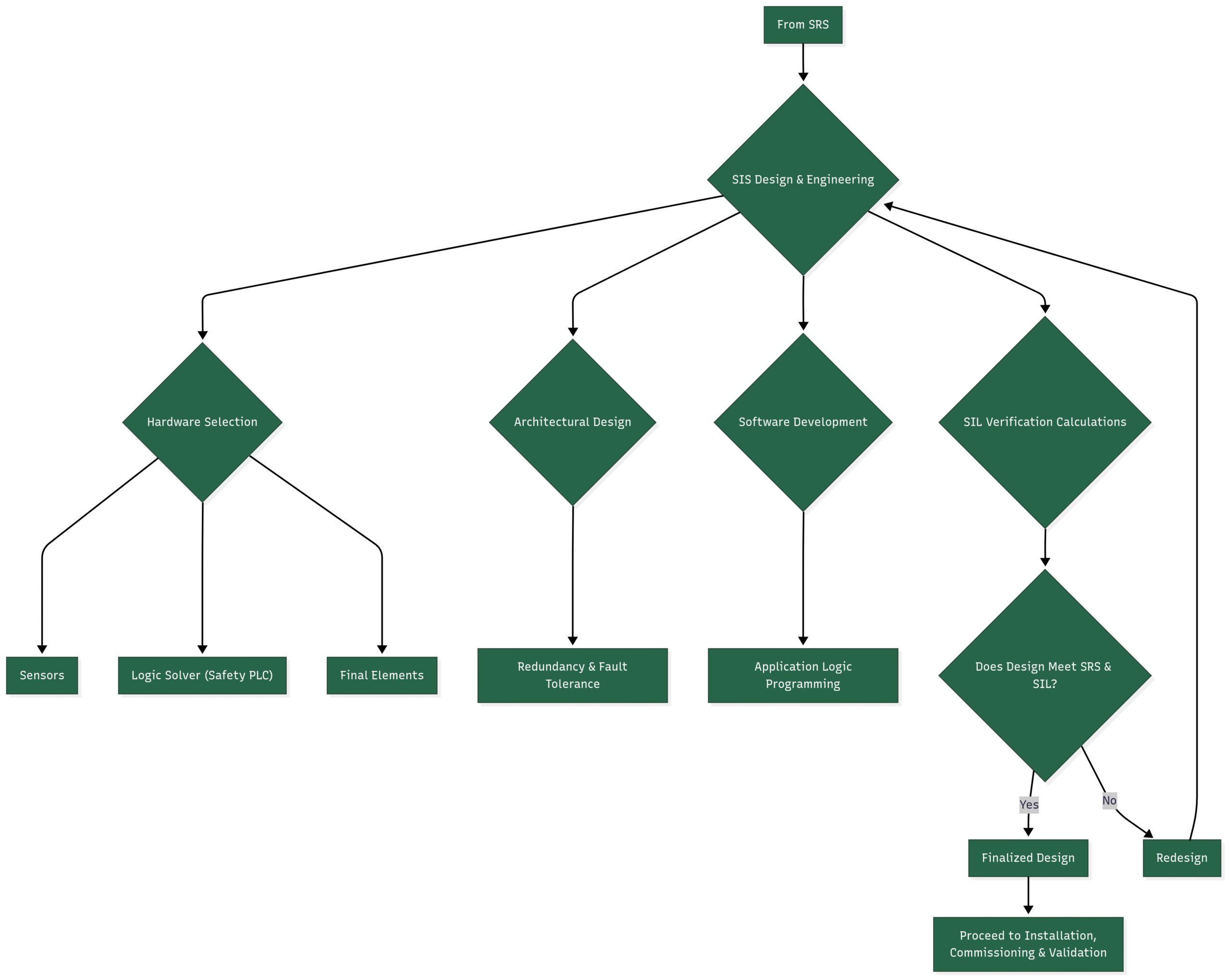
With the SRS as the guide, the detailed design and engineering of the Safety Instrumented System can begin. This phase involves selecting appropriate hardware and software and designing the system architecture to meet the specified safety and integrity requirements.
Key Activities:
Technology and Component Selection: Choosing certified or “proven-in-use” sensors, logic solvers (e.g., safety PLCs), and final elements (e.g., valves, actuators) that meet the required SIL.
Architectural Design: Determining the level of redundancy (e.g., 1-out-of-2, 2-out-of-3 voting) needed to achieve the target SIL and to tolerate potential hardware faults.
SIL Verification: Performing calculations to verify that the designed SIFs meet their target SIL. This involves analyzing the probability of failure on demand (PFDavg) for each SIF.
Software Design: Developing and verifying the application logic for the safety PLC.
Block Diagram: Design and Engineering
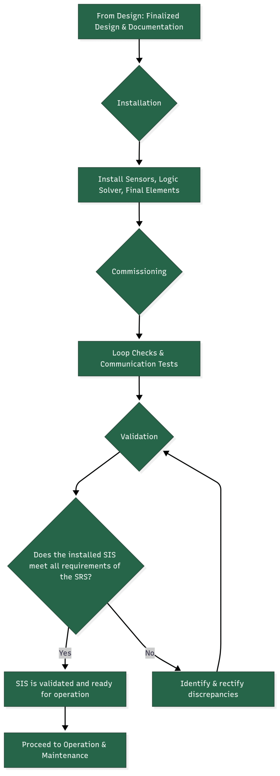
Phase 5: Installation, Commissioning, and Validation
This phase marks the transition from the drawing board to the physical plant. The designed SIS is installed, tested, and validated to ensure it functions as intended before being put into service.
Key Activities:
Installation: The physical installation of all SIS components according to the design documents.
Commissioning: A series of checks and tests to ensure that the installed components are correctly connected and communicating. This includes loop checks and function tests.
Validation: The final confirmation that the installed and commissioned SIS meets all the requirements laid out in the SRS. This is a critical step to ensure that the right system has been built correctly.
Block Diagram: Installation, Commissioning, and Validation
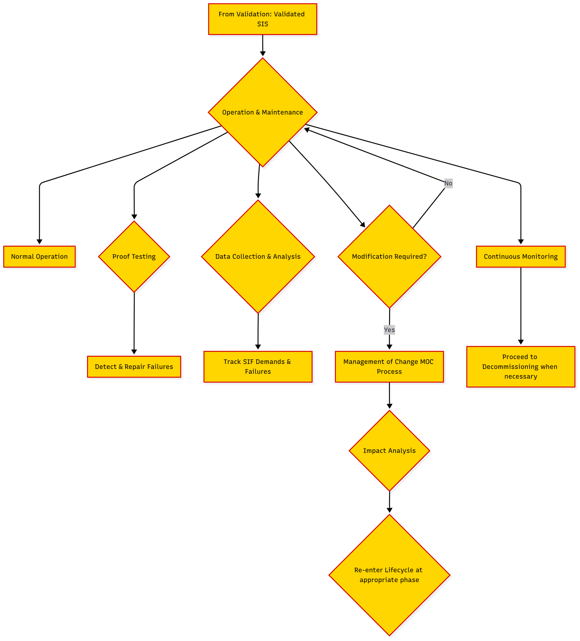
Phase 6: Operation, Maintenance, and Modification
The operation and maintenance phase is the longest part of the safety lifecycle, spanning the operational life of the plant. The goal during this phase is to maintain the integrity of the SIS and ensure it remains effective in providing the required risk reduction.
Key Activities:
Operation: Operating the SIS within its design limits and ensuring that operators are trained and competent.
Maintenance: Performing routine maintenance activities, including proof testing, to detect and repair any dangerous hidden failures in the SIS.
Modification (Management of Change): Any changes to the SIS, no matter how small, must be carefully managed through a formal Management of Change (MOC) process. This ensures that the impact of the change on functional safety is assessed and the SIS integrity is not compromised.
Data Collection and Analysis: Collecting data on SIF demands, failures, and proof test results to monitor the performance of the SIS and identify any trends that may indicate a degradation in safety.
Block Diagram: Operation, Maintenance, and Modification
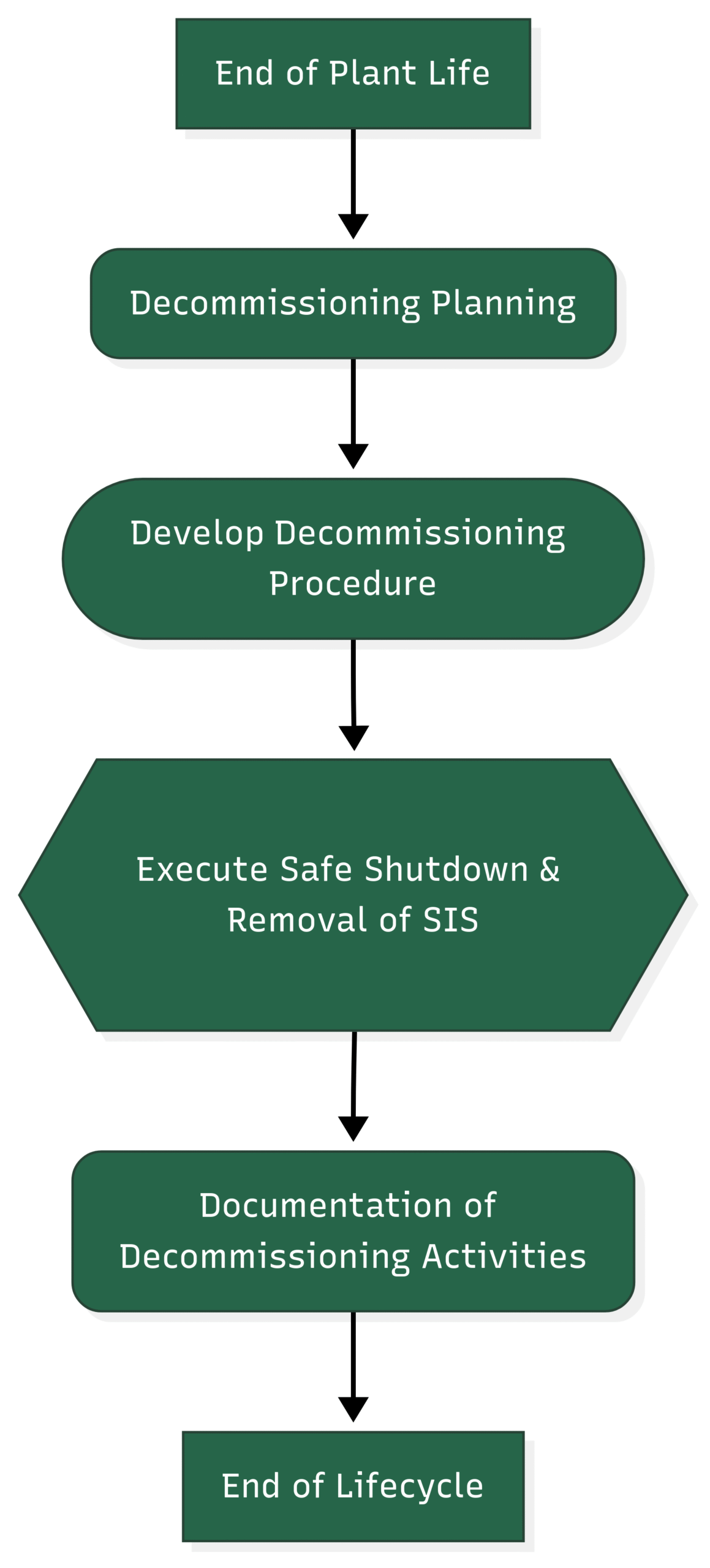
Phase 7: Decommissioning
The final phase of the functional safety lifecycle is the decommissioning of the SIS. This phase is initiated when the process unit is taken out of service permanently.
Key Activities:
Planning: Developing a detailed plan for the safe decommissioning of the SIS.
Execution: Carrying out the decommissioning activities in a controlled and safe manner, ensuring that there are no unintended consequences for other systems or the environment.
Block Diagram: Decommissioning
ConclusionThe IEC 61511 functional safety lifecycle provides a robust and comprehensive framework for managing the safety of industrial processes. By diligently following each phase, from the initial hazard and risk assessment to the final decommissioning, organizations can build and maintain a culture of safety that protects people, the environment, and their business. The lifecycle is not a one-time event but a continuous journey of improvement, ensuring that safety remains a top priority throughout the life of a facility. Embracing this lifecycle approach is a fundamental step towards achieving excellence in process safety management.