Best Practices for Control Valve Calibration and Stroke Checking
In the intricate world of industrial process control, the humble control valve plays a pivotal role. It is the final control element, the muscle that acts on the commands of the brain – the distributed control system (DCS) or programmable logic controller (PLC). The precise and reliable operation of these valves is paramount to ensuring product quality, operational efficiency, and, most importantly, plant safety. This is where the critical practices of control valve calibration and stroke checking come into play.
This comprehensive guide will delve into the best practices for control valve calibration and stroke checking, providing a detailed roadmap for ensuring your control valves operate at peak performance. We will explore the “why” behind these procedures, the step-by-step “how,” and provide illustrative block diagrams to clarify the processes.
The Unseen Importance: Why We Calibrate and Stroke Check
Imagine a scenario where a control valve responsible for regulating the flow of a critical chemical reactant is not properly calibrated. A 50% open signal from the controller might result in the valve being 60% open, or perhaps only 40%. This discrepancy can lead to off-spec products, increased waste, and potentially hazardous process conditions.
Calibration is the process of configuring a control valve’s positioner to ensure that the actual valve travel corresponds linearly and accurately to the control signal it receives. A properly calibrated valve will move to 25% of its travel for a 25% input signal, 50% for a 50% signal, and so on, throughout its entire operating range.
Stroke checking, on the other hand, is a verification process. It’s a health check to confirm that the valve can physically travel through its full range of motion, from fully closed to fully open and back again, without any obstructions, sticking, or jerky movements. It helps identify potential mechanical issues that calibration alone might not reveal.
The key benefits of a robust calibration and stroke checking program include:
- Enhanced Process Control: Accurate valve positioning leads to tighter control over process variables like flow, pressure, temperature, and level.
- Improved Product Quality: Consistent and precise control minimizes process variability, resulting in a more uniform and on-specification product.
- Increased Efficiency and Reduced Waste: Optimal control reduces the consumption of raw materials and energy while minimizing the production of off-spec material.
- Enhanced Safety: In critical applications, a properly functioning control valve is a vital safety barrier. Incorrect valve operation can have catastrophic consequences.
- Proactive Maintenance: Regular stroke checks can help identify developing mechanical problems like worn seals, actuator issues, or internal obstructions before they lead to a catastrophic failure.
- Compliance with Industry Standards: Many industries have regulations and standards (e.g., ISA/IEC) that mandate regular calibration and testing of critical control elements.
Pre-Calibration and Pre-Stroke Check Essentials: Setting the Stage for Success
Before diving into the calibration or stroke checking procedure, a series of preparatory steps are crucial to ensure safety and the accuracy of the results.
- Obtain Necessary Permits: Always follow your facility’s work permit and safety procedures. This includes lockout/tagout (LOTO) procedures to isolate the valve from the process and any energy sources.
- Inform Operations: Communicate with the control room operators and area personnel about the work being performed. The control loop for the valve should be put in “manual” mode to prevent the controller from sending unexpected signals.
- Gather Your Tools: A typical toolkit for calibration and stroke checking includes:
- A calibrated multifunction process calibrator (for sourcing and measuring mA signals).
- A set of hand tools (wrenches, screwdrivers, etc.).
- A pressure regulator and a calibrated pressure gauge for pneumatic valves.
- A HART (Highway Addressable Remote Transducer) communicator for smart positioners.
- Personal Protective Equipment (PPE) appropriate for the process fluid and environment.
- The valve’s datasheet or manual.
- Visual Inspection: Before connecting any equipment, perform a thorough visual inspection of the control valve assembly. Look for signs of corrosion, leaks, loose connections, or physical damage to the valve body, actuator, or positioner.
The Heart of the Matter: The Control Valve Calibration Process
The exact calibration procedure can vary depending on the type of valve, actuator (pneumatic, electric), and positioner (conventional, smart/digital). However, the fundamental principles remain the same.
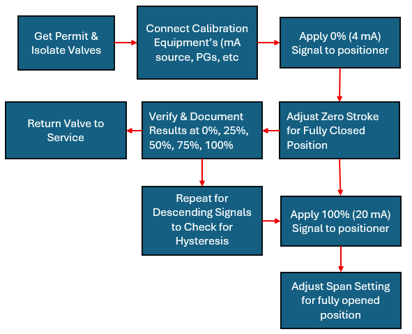
Block Diagram: General Control Valve Calibration Process
Step-by-Step Calibration of a Pneumatic Control Valve with a Conventional Positioner:
- Isolate and Prepare: Follow all the pre-calibration checks mentioned earlier.
- Connect Equipment:
- Connect the output of your pressure regulator to the air supply port of the positioner.
- Connect your calibrated pressure gauge to the positioner’s output to monitor the air pressure going to the actuator.
- Connect the mA source from your process calibrator to the input signal terminals of the positioner.
- Set the Zero Point:
- Apply a 4mA signal (for a standard 4-20mA range) from your calibrator. This represents the 0% open command.
- Observe the valve’s position indicator. It should be at the fully closed position.
- If not, adjust the “zero” screw or knob on the positioner until the valve is just fully closed. You may need to slightly increase the signal (e.g., to 4.1mA) to see the initial movement and then bring it back to 4mA to confirm the zero setting.
- Set the Span (Full Scale):
- Apply a 20mA signal from your calibrator. This represents the 100% open command.
- Observe the valve’s position indicator. It should be at the fully open position.
- If not, adjust the “span” or “range” screw or knob on the positioner until the valve reaches its full travel.
- Iterate and Verify:
- Adjusting the span can sometimes slightly affect the zero setting, and vice versa. It’s essential to repeat steps 3 and 4 until both the 4mA (0%) and 20mA (100%) points are correctly set.
- Linearity Check: Once the zero and span are set, check the valve’s response at intermediate points:
- Apply an 8mA signal (25% open) and verify the valve position.
- Apply a 12mA signal (50% open) and verify the valve position.
- Apply a 16mA signal (75% open) and verify the valve position.
- Hysteresis Check: Hysteresis is the difference in valve position for the same input signal when approached from opposite directions. To check for this, after reaching 20mA, decrease the signal in the same increments (16mA, 12mA, 8mA, 4mA) and compare the valve positions to those recorded during the increasing signal test. A small amount of hysteresis is normal, but excessive hysteresis can indicate internal friction or a faulty positioner.
- Document and Restore: Record all your “as found” and “as left” calibration data. Disconnect your test equipment and restore the valve to its normal operating condition. Inform the control room that the work is complete and the loop can be returned to automatic mode.
Calibrating a Smart Positioner:
Smart or digital positioners offer a more automated and precise calibration process. The general steps are similar, but the adjustments are typically made through a HART communicator or a connected laptop with the appropriate software.
- Connect: Connect the HART communicator in parallel with the control signal lines.
- Initiate Auto-Calibration: Navigate through the menu of the HART communicator to find the auto-calibration or self-tuning function.
- Follow Prompts: The smart positioner will then automatically stroke the valve, learn its zero and end positions, and linearize its response. It will often provide a detailed report on the valve’s performance, including friction, deadband, and response time.
- Manual Trim (if necessary): In some cases, a manual trim of the zero and span points may still be required through the communicator’s interface for fine-tuning.
The All-Important Stroke Check: A Valve’s Physical Exam
While calibration ensures the positioner is doing its job, a stroke check verifies the entire valve assembly’s mechanical integrity.
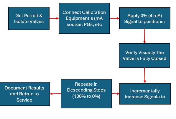
Block Diagram: Control Valve Stroke Checking Procedure
Step-by-Step Stroke Checking Procedure:
- Preparation: As with calibration, ensure the valve is isolated and all safety precautions are in place.
- Connect Signal Source: Connect a calibrated mA source to the positioner’s input.
- From Closed to Open:
- Start by applying a 4mA signal to command the valve to its fully closed position. Visually confirm that the valve stem or shaft is at the end of its travel and that there are no audible leaks.
- Incrementally increase the signal in 25% steps (8mA, 12mA, 16mA, 20mA).
- At each step, visually inspect the valve’s position indicator to ensure it corresponds to the commanded position.
- Listen for any unusual noises, such as grinding or scraping, which could indicate a mechanical issue.
- Observe the movement of the stem. It should be smooth and steady, not jerky or hesitant.
- From Open to Closed:
- Once the valve is fully open at 20mA, reverse the process.
- Decrease the signal in 25% steps (16mA, 12mA, 8mA, 4mA).
- Again, verify the valve position at each step and observe for smooth operation.
- Full Stroke Test: It’s also good practice to perform a full stroke test by rapidly changing the signal from 4mA to 20mA and then from 20mA back to 4mA. This helps to check the valve’s dynamic response and can reveal issues that a slower, stepped test might miss.
- Analyze and Document: If the valve fails to travel its full stroke, sticks at any point, or exhibits jerky movement, it’s a clear indication of a mechanical problem that needs further investigation and repair. Document the results of the stroke check, noting any anomalies.
Troubleshooting Common Calibration and Stroke Checking Issues
Conclusion: A Foundation for Reliable Process Control
Control valve calibration and stroke checking are not merely routine maintenance tasks; they are foundational pillars of a reliable and efficient process control strategy. By implementing a consistent and thorough program based on these best practices, you can ensure that your control valves operate as intended, safeguarding your processes, products, and personnel. The time and effort invested in proper calibration and stroke checking will pay significant dividends in the form of improved performance, reduced downtime, and a safer working environment. Remember, a well-calibrated control valve is a happy control valve, and a happy control valve is the cornerstone of a well-controlled process.
very interesting information! .