Best Practices for Implementing SIS per IEC 61511
In the intricate and often hazardous world of the process industry, ensuring the safety of personnel, the environment, and assets is not just a priority; it’s a mandate. At the heart of modern process safety lies the Safety Instrumented System (SIS), a critical layer of protection designed to automatically bring a process to a safe state when unforeseen or dangerous conditions arise. The international standard IEC 61511 provides a comprehensive framework for the design, implementation, and management of these vital systems.
Adherence to IEC 61511 is not merely a matter of compliance; it is a commitment to a disciplined and systematic approach to safety. For engineering, maintenance, and operations professionals, a deep understanding of its principles is paramount. This blog post delves into the best practices for implementing a Safety Instrumented System in accordance with IEC 61511, navigating through the entire safety lifecycle from conception to decommissioning, and is complemented by block diagrams to illuminate key concepts.
The Foundation: Understanding the IEC 61511 Safety Lifecycle
The IEC 61511 standard is structured around the concept of a safety lifecycle, a cradle-to-grave approach that ensures safety is considered at every stage of the SIS’s existence. This lifecycle approach is fundamental to achieving functional safety and can be visualized as a continuous loop of assessment, realization, and maintenance.
Block Diagram 1: The IEC 61511 Safety Lifecycle
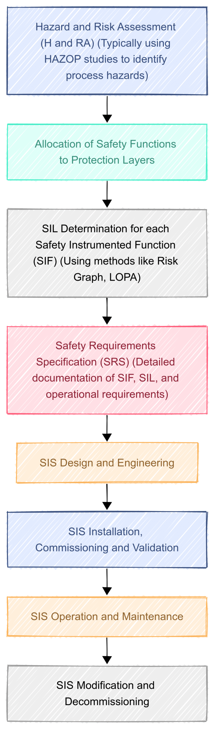
Each phase of this lifecycle has its own set of requirements and best practices, all of which are interconnected and crucial for the overall integrity of the safety system.
Phase 1: The Analysis Phase – Laying the Groundwork for Safety
The initial phase of the safety lifecycle is dedicated to understanding the risks inherent in a process and determining the necessary safety measures. This phase is arguably the most critical, as any errors or omissions here will cascade through the entire lifecycle.
1. Hazard and Risk Assessment (H&RA): The journey begins with a systematic identification of potential hazards and an evaluation of the associated risks. Methodologies like Hazard and Operability (HAZOP) studies are commonly employed to scrutinize the process design and identify potential deviation scenarios that could lead to hazardous events. The key best practices in this stage include:
Multidisciplinary Team: The H&RA team should comprise individuals with diverse expertise, including process engineering, operations, maintenance, and safety. This ensures a holistic view of the potential risks.
Thorough Documentation: Every identified hazard, its cause, and its potential consequences must be meticulously documented. This documentation forms the basis for all subsequent safety decisions.
Considering all Operating Modes: The assessment should not be limited to normal operation. It must also consider startup, shutdown, and other foreseeable abnormal conditions.
2. Allocation of Safety Functions to Protection Layers: Not all risks warrant the implementation of an SIS. A fundamental concept in process safety is the “layers of protection” model. These layers can include the basic process control system (BPCS), alarms, and physical protection devices like pressure relief valves. The SIS is a crucial, but not the only, layer.
Layer of Protection Analysis (LOPA): LOPA is a semi-quantitative tool used to determine if the existing protection layers are sufficient to reduce the risk to a tolerable level. It helps in deciding whether a Safety Instrumented Function (SIF) is required and, if so, what its target Safety Integrity Level (SIL) should be.
Independence of Protection Layers: A critical principle is that each protection layer should be independent of the others. The failure of one layer should not compromise the effectiveness of another.
3. Safety Requirements Specification (SRS): Once the need for a SIF has been established, a comprehensive Safety Requirements Specification (SRS) must be developed. The SRS is the cornerstone document for the SIS, detailing what the system is supposed to do and under what conditions.
A robust SRS should, at a minimum, include:
A clear description of the safety function.
The definition of the safe state for the process.
The required SIL for the SIF.
The process safety time – the time available to prevent the hazardous event after a demand.
Requirements for manual shutdown, startup overrides, and maintenance bypasses.
The expected proof test interval.
The SRS serves as the design brief for the engineering team and the benchmark against which the final system will be validated.
Phase 2: The Realization Phase – Building the Safety Net
With a clear understanding of the safety requirements, the focus shifts to designing, engineering, and implementing the SIS.
1. SIS Design and Engineering: This is where the conceptual safety requirements are translated into a tangible system. Best practices in this phase are geared towards ensuring reliability, fault tolerance, and adherence to the SRS.
Block Diagram 2: A Typical SIS Architecture
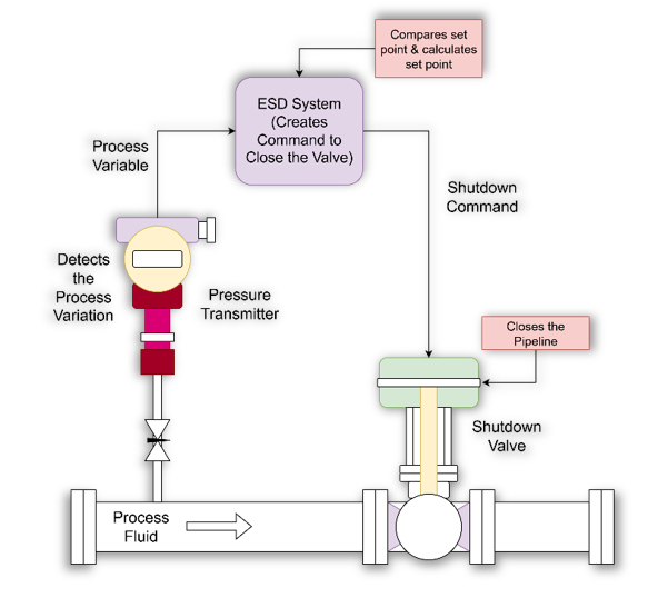
Key considerations during design include:
Technology Selection: Choosing appropriate sensors, logic solvers (e.g., safety PLCs), and final elements (e.g., shutdown valves) is critical. The selected components should be certified for use in safety applications and meet the required SIL.
Architectural Constraints (Hardware Fault Tolerance): IEC 61511 specifies minimum hardware fault tolerance (HFT) requirements based on the SIL. This often necessitates the use of redundancy (e.g., 1-out-of-2 or 2-out-of-3 voting arrangements) to ensure the system can tolerate component failures.
Separation and Segregation: The SIS should be physically and functionally separate from the Basic Process Control System (BPCS). This independence prevents a failure in the BPCS from compromising the SIS.
SIL Verification: Throughout the design process, it’s crucial to perform SIL verification calculations. This involves analyzing the probability of failure on demand (PFD) of the entire SIF, considering the failure rates of all its components, the proof test interval, and the diagnostic coverage. The calculated PFD must be better than the target set by the SIL.
2. SIS Implementation and Commissioning: This phase involves the physical installation of the SIS components and the software programming of the logic solver.
Competent Personnel: All implementation activities must be carried out by competent and trained personnel who understand the critical nature of the system.
Strict Adherence to Design: The installation must strictly follow the design specifications. Any deviations must be formally managed through a management of change (MOC) process.
Thorough Testing: Before the system goes live, it must undergo rigorous testing to ensure it functions as intended. This includes loop checks, logic solver testing, and functional testing of the entire SIF.
Phase 3: The Operational Phase – Maintaining the Vigil
An SIS is not a “fit and forget” system. Its integrity must be maintained throughout its operational life.
1. SIS Validation: Before the SIS is put into service, it must be formally validated. Validation is the process of confirming that the installed and commissioned SIS meets all the requirements laid out in the SRS. This is a crucial final check to ensure the right system has been built for the intended safety application.
2. Operation and Maintenance: The long-term reliability of the SIS depends on robust operation and maintenance procedures.
Proof Testing: Regular proof testing is mandatory to detect any dangerous, undetected failures in the SIS components. The frequency and scope of these tests are determined during the design phase and documented in the SRS.
Management of Bypasses: There will be times when a SIF needs to be bypassed for maintenance. Strict procedures must be in place to manage these bypasses, including authorization, logging, and ensuring alternative safety measures are in place.
Personnel Training: Operations and maintenance personnel must be thoroughly trained on the purpose, functionality, and procedures related to the SIS.
Data Collection and Analysis: It’s essential to collect and analyze data on SIS performance, including demands on the system, spurious trips, and proof test results. This data can provide valuable insights into the system’s reliability and identify areas for improvement.
3. Modification: Any modification to the SIS, no matter how small, must be subject to a formal Management of Change (MOC) process. The MOC process should ensure that the proposed change is properly assessed for its impact on safety and that the safety lifecycle is re-entered at the appropriate phase.
4. Decommissioning: When a process or plant is decommissioned, the SIS must also be decommissioned in a safe and controlled manner.
The Overarching Principle: Functional Safety Management
Underpinning the entire safety lifecycle is the concept of Functional Safety Management (FSM). FSM encompasses the overall policies, procedures, and responsibilities for ensuring functional safety throughout the lifecycle. Key elements of a robust FSM system include:
A clear safety policy and objectives.
Defined roles and responsibilities for all personnel involved in the safety lifecycle.
Competency assessment and management for all personnel.
Procedures for all lifecycle activities.
Regular functional safety audits and assessments.
Conclusion: A Culture of Safety
Implementing a Safety Instrumented System in accordance with IEC 61511 is a journey that demands diligence, expertise, and a steadfast commitment to safety. It is not a one-time project but a continuous process of assessment, realization, and maintenance. By embracing the principles of the safety lifecycle, fostering a strong culture of safety, and leveraging the expertise of competent professionals, organizations in the process industry can build and maintain a robust guardian for their people, the environment, and their assets. The best practices outlined in this post provide a roadmap to achieving this critical objective, ensuring that when the unexpected happens, the final line of defense holds strong.