An Expert Analysis of Bubble Type Level Transmitter Systems: Principles, Applications, and Best Practices
The Hydrostatic Principle of Bubble Tube Level Measurement
The operational efficacy of the bubble type level transmitter is rooted in the fundamental laws of fluid mechanics, specifically the principle of hydrostatic pressure. This section establishes the foundational physics governing the technology, moving from the general theory of hydrostatic pressure to its specific and elegant application in this measurement system. A clear understanding of the relationship between the physical properties of the liquid, the dynamics of the purge gas, and the resulting back pressure is essential for appreciating both the capabilities and the limitations of this method.
The Physics of Hydrostatic Pressure in Level Sensing
At its core, hydrostatic level measurement leverages the direct relationship between the height of a static fluid column and the pressure it exerts at its base. This pressure, known as hydrostatic pressure, is a function of the liquid’s density (ρ), the acceleration due to gravity (g), and the height of the liquid column (h). The relationship is expressed by the fundamental formula:
P=ρ*g*h
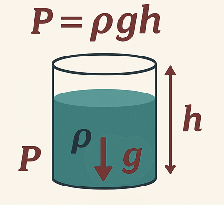
A critical concept underpinning this measurement is the “hydrostatic paradox,” which posits that the pressure at any given depth within a continuous fluid is dependent only on the vertical height of the fluid above that point, irrespective of the vessel’s shape or total volume. This principle ensures that a measurement taken at the bottom of a tall, narrow standpipe will be identical to one taken at the same depth in a large, wide tank, provided the liquid and its height are the same. This independence from vessel geometry is what allows the bubbler method to be applied universally across various tank designs.
The total pressure measured at the bottom of a vessel is a composite of two components: the hydrostatic pressure exerted by the liquid column itself, and any additional pressure acting on the surface of the liquid, such as atmospheric pressure in an open tank or a pressurized gas blanket in a closed vessel. This distinction is crucial and dictates the specific configuration of the pressure measurement system, as will be explored later.
Translating Liquid Head to Back Pressure: The Role of the Purge Gas
The defining characteristic of the bubble type level transmitter is its indirect method of pressure measurement. Instead of placing a pressure sensor directly in contact with the process fluid, the system uses a purge gas—typically clean, dry air or, for reactive processes, an inert gas like nitrogen—to transfer the pressure information to a remote sensor.
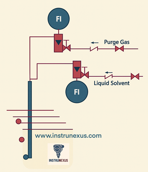
The mechanism is straightforward yet effective. A constant, low-volume flow of gas is directed into a dip tube (also called a bubble tube or orifice line) that is installed vertically in the vessel, with its open end positioned near the bottom. For the gas to escape from the submerged end of the tube and form bubbles, its internal pressure must be sufficient to overcome the opposing hydrostatic pressure exerted by the column of liquid above the tube’s outlet.
As the system reaches equilibrium, the gas pressure inside the entire length of the dip tube equalizes with the hydrostatic pressure at the point of discharge. This back pressure is a direct and proportional measure of the liquid level. This process effectively creates a pneumatic signal that mirrors the hydrostatic head. A pressure transmitter, safely located away from the potentially harsh process environment, measures this back pressure to determine the liquid level. This physical separation of the sensitive measurement electronics from the process medium is the primary source of the bubbler system’s robustness and a key reason for its selection in challenging applications. The entire apparatus can be understood not merely as a sensor, but as a complete pneumatic transducer system that converts the physical property of liquid head into a stable, measurable gas pressure before any electronic conversion takes place.
Key Parameters: Gas Flow Rate, Liquid Density, and Measurement Accuracy
While the operating principle is simple, achieving high-fidelity measurements requires careful management of several key variables. The apparent simplicity of the method belies an operational complexity that must be addressed to ensure precision.
Gas Flow Rate: The accuracy of the measurement is highly sensitive to the flow rate of the purge gas. The flow must be maintained at a low and constant rate, typically just enough to produce a few bubbles per second. This minimal flow ensures that the pressure measured is almost entirely due to the hydrostatic head. If the flow rate is too high, it introduces a significant frictional pressure drop along the length of the tubing. This frictional pressure adds to the hydrostatic pressure, causing the transmitter to register a falsely high level reading. Conversely, if the gas flow is interrupted for any reason, the measurement will be lost, and the process liquid may backflow into the dip tube, leading to plugging and system failure. The objective is to establish a flow that is just sufficient to prevent liquid ingress and overcome the head pressure, without introducing erroneous frictional components.
Liquid Density: As a hydrostatic measurement technique, the bubbler system’s accuracy is fundamentally dependent on the specific gravity (density) of the process liquid. The controller calculates the level (h) by dividing the measured pressure (P) by the product of density (ρ) and gravity (g). Consequently, any uncompensated change in the liquid’s density—due to temperature variations, changes in composition, or aeration—will result in a direct and proportional error in the calculated level. This reliance on a known and stable density is a critical limitation shared by all hydrostatic level measurement methods.
Bubble Formation: The physical characteristics of the bubbles themselves can influence measurement stability. The intermittent release of large bubbles can cause pressure pulsations in the dip tube, leading to a noisy or fluctuating output signal. To ensure a smooth and stable back pressure, the tip of the dip tube is often designed with a V-notch or is cut at an angle. This encourages the formation of a steady stream of small, consistent bubbles, which minimizes pressure variations and improves the overall precision of the measurement. A slight pressure variation with the release of each bubble is an inherent artifact of the method, with the magnitude of the fluctuation being approximately equal to the hydrostatic pressure of a fluid column the height of the bubble’s diameter.
Open vs. Closed Tank Configurations
The architecture of the bubbler system is adapted based on whether the vessel is open to the atmosphere or is a sealed, pressurized system.
Open (Vented) Tanks: In a tank that is vented to the atmosphere, the pressure on the surface of the liquid is constant atmospheric pressure. The system measures the back pressure in the dip tube relative to this atmospheric reference. This is typically achieved by using a gauge pressure transmitter, where the low-pressure side of the sensing element is simply vented to the surrounding air. The measured gauge pressure is then directly proportional to the liquid level.
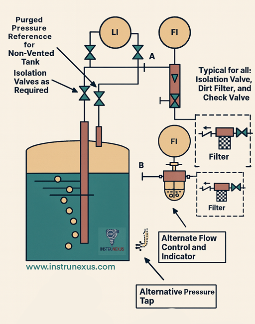
Closed (Pressurized) Tanks: For applications involving a closed tank with a pressurized vapor space above the liquid, a simple gauge pressure measurement would be erroneous, as it would combine the hydrostatic head with the variable tank pressure. To isolate the level measurement, a differential pressure (DP) transmitter is required. In this configuration, the high-pressure (HP) port of the DP transmitter is connected to the bubbler’s dip tube, measuring the sum of the hydrostatic pressure and the tank’s vapor pressure. The low-pressure (LP) port is connected to a separate tap in the vapor space at the top of the tank. The DP transmitter electronically subtracts the low-side pressure from the high-side pressure, effectively canceling out the common-mode tank pressure and yielding a differential pressure that is solely representative of the liquid’s hydrostatic head.
System Architecture and Core Components
A bubble type level transmitter is not a single, monolithic sensor but rather an integrated system comprising pneumatic, mechanical, and electronic components working in concert. The reliability and accuracy of the final level measurement are contingent upon the proper function and interplay of each element in this chain. This modularity, while introducing complexity, also allows for a high degree of customization to suit specific and often challenging process environments.
The Purge Gas Supply Subsystem
The foundation of any bubbler system is a consistent and reliable source of purge gas.
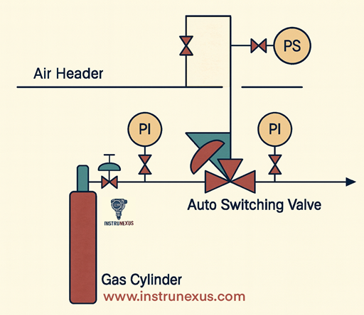
Source: The gas can be supplied by dedicated, often redundant, air compressors for critical applications or drawn from a facility’s existing instrument air network. The choice of gas is dictated by the process. While compressed air is most common due to its availability, processes that are sensitive to oxidation or contamination require the use of an inert gas, such as dry nitrogen.
Pressure Requirements: A fundamental prerequisite is that the supply pressure must always be greater than the maximum anticipated back pressure. This includes the hydrostatic pressure at the highest liquid level, any static pressure in a closed tank, and all frictional losses in the system’s tubing. As a practical guideline, a supply pressure of 25 psig (approximately 1.7 bar) is considered sufficient for measuring liquid levels up to 30 feet (approximately 9.1 meters).
Gas Conditioning and Control
The quality and control of the purge gas are paramount for accurate and long-term reliable operation.
Filters/Dryers: The purge gas must be meticulously clean and dry. Any moisture present in the gas lines can condense and freeze in cold ambient conditions, leading to blockages and complete measurement failure. Furthermore, moisture can cause corrosion of sensitive internal pneumatic components over time. To mitigate this, systems are equipped with coalescing filters to remove particulates and oil, and desiccant cartridges or air dryers to eliminate moisture. Regular draining of filter bowls and monitoring of desiccant status are critical maintenance tasks.
Pressure Regulator: A pressure regulator is installed downstream of the main supply to reduce the high-pressure source to a lower, stable working pressure suitable for the system. More advanced systems may employ a differential pressure regulator. This device intelligently maintains a constant pressure differential above the measured back pressure, automatically adjusting the purge pressure as the tank level changes. This ensures the formation of optimal-sized bubbles across the entire measurement range, enhancing accuracy and minimizing gas consumption.
Flow Control (Flow Meter/Rotameter): A means of restricting and monitoring the gas flow rate is essential. This is typically achieved with a precision needle valve paired with a visual flow indicator, such as a rotameter. This assembly allows the operator to set and verify the low, constant flow rate required for accurate measurement, as detailed in Section 1.3.
The Sensing Element: Dip Tube (or Bubble Tube)
The dip tube is the workhorse of the system and the only component that directly interfaces with the process fluid.
Function: It serves as the conduit to deliver the purge gas to a fixed point near the bottom of the vessel.
Material: The selection of the dip tube material is critical and must be based on the chemical properties of the liquid being measured. For benign applications like water, plastic tubing may suffice. For aggressive or corrosive chemicals, materials such as stainless steel, Kynar (PVDF), Teflon (PTFE), or polypropylene are required to prevent degradation and ensure system integrity.
Installation: Proper installation is vital for stable measurements. The tube must be rigidly secured to prevent any movement or vibration, as this would alter the effective measurement depth and cause the pressure reading to fluctuate. It should be positioned in a location that is representative of the overall tank level but away from direct inflow streams or areas of high agitation. To avoid blockages from sediment or sludge, the tube’s outlet is typically positioned a minimum of 3 to 6 inches (75 to 150 mm) from the tank floor.
The Measurement and Transmission Subsystem
This subsystem converts the pneumatic signal into a usable electronic format and calculates the final level value.
Pressure Transmitter: A gauge or differential pressure (DP) transmitter is plumbed into the gas line between the flow controller and the dip tube. This device precisely measures the back pressure created by the liquid head. It then transduces this pressure reading into a standardized industrial signal, most commonly a 4-20 mA analog current loop, which is robust against electrical noise over long transmission distances.
Controller/Display: The 4-20 mA signal from the transmitter is fed into a receiving device, such as a Programmable Logic Controller (PLC), Remote Terminal Unit (RTU), or a dedicated data logger. This controller is programmed with the specific gravity of the liquid to perform the final calculation (h=P/ρg) and convert the pressure signal into an engineering unit of level (e.g., feet, meters, or percent full). Modern bubbler systems are often available as self-contained, “smart” units that integrate the gas control, pressure sensor, and controller into a single package. These systems may feature onboard displays, data logging capabilities to USB drives, and intuitive browser-based software for configuration, eliminating the need for an external recording device.
Communication: To integrate with plant-wide control and monitoring systems, bubbler controllers typically support a variety of industrial communication protocols, including SDI-12 (common in environmental monitoring), MODBUS, and HART.
Ancillary Components
The modular nature of bubbler systems allows for the inclusion of various ancillary components to enhance performance and reliability in specific applications.
Purge Systems: In applications involving slurries, sludge, or liquids prone to crystallization, the dip tube is at high risk of clogging. To counteract this, systems can be equipped with a high-pressure purge or “blow-down” feature. This typically involves a solenoid valve that, when activated either manually by a pushbutton or automatically by a timer, isolates the pressure transmitter and directs a high-pressure blast of gas down the dip tube to clear any obstructions.
Enclosures: The control panel housing the transmitter, regulators, and other sensitive components must be protected from the ambient environment. Enclosures are specified based on the installation area, with NEMA 4X (or equivalent IP rating) being common for protection against dust and water ingress. For outdoor installations in cold climates, these enclosures can be fully insulated and equipped with internal heaters to prevent freezing of pneumatic components and ensure stable operation of electronics.
Tubing and Fittings: A network of pneumatic tubing and fittings connects the various components. Materials range from Polyflo plastic tubing for general use to stainless steel for higher pressures or more demanding environments. Fitting types include push-to-connect for ease of assembly and compression fittings for high-integrity, leak-proof connections.
Table 2.1: Core Components of a Bubbler Level System
The following table summarizes the primary function and key considerations for each major component within a typical bubbler level measurement system.

Operational Advantages and Inherent Limitations
A comprehensive evaluation of any measurement technology requires a balanced and critical assessment of its strengths and weaknesses. The bubble type level transmitter, having been a staple of industrial measurement for decades, possesses a well-understood performance profile. Its continued use is a testament to a unique set of advantages that make it the optimal choice in specific, often demanding, scenarios. However, these advantages are coupled with inherent limitations that must be carefully considered during the selection process.
Key Advantages
![]()
The primary justifications for selecting a bubbler system are centered on its exceptional robustness and reliability in environments where other technologies falter.
Reliability in Harsh Media: The bubbler’s most significant advantage is the isolation of its sensitive electronic components from the process fluid. Only the simple, passive dip tube comes into contact with the liquid. This design makes it an ideal solution for measuring the level of highly corrosive, viscous, hot (including molten metal), slurry-type, or solids-laden liquids such as sewage and sludge, which would quickly damage or foul directly-immersed sensors.
Immunity to Surface Conditions: The measurement principle is based on the hydrostatic pressure at a submerged point, making it completely unaffected by conditions at the liquid’s surface. Heavy foam, vapors, steam, surface turbulence from agitation, or floating debris, which are common sources of error for non-contact technologies like ultrasonic and some radar sensors, have no impact on the bubbler’s reading.
Remote Sensor Placement: The pressure transmitter and the entire control panel can be located a significant distance—potentially several hundred feet—from the actual measurement point in the vessel. This offers several benefits: it allows for installation in hazardous or classified areas (as there are no electrical components at the point of measurement), provides access to measurement points in physically inaccessible locations like deep wells or sumps, and centralizes maintenance activities in a safe and convenient location.
Simplicity and Field Repairability: The system is fundamentally composed of well-understood mechanical and pneumatic components like regulators, valves, and tubing. This inherent simplicity often makes troubleshooting more intuitive and allows for field repairs with standard tools, a crucial advantage in critical processes or remote locations where specialized electronic diagnostic equipment may not be available.
Cost-Effectiveness (Initial): The initial capital cost of a basic bubbler system can be lower than that of more technologically advanced alternatives like radar or guided wave radar, making it an attractive option for budget-conscious projects.
No Moving Parts in the Process: Within the vessel itself, the dip tube is a completely stationary component. This lack of moving parts eliminates a common source of mechanical wear and failure, contributing to the system’s long-term reliability when properly maintained. This claim, however, warrants a more nuanced examination. While true for the wetted components, the overall system relies on an external air compressor, which is a significant mechanical device with its own maintenance requirements and potential failure modes. This “no moving parts paradox” highlights that the system’s reliability is a function of the entire assembly, not just the in-tank element.
Inherent Limitations
The operational model of the bubbler system also introduces several limitations and ongoing operational requirements.
![]()
Requirement for a Continuous Gas Supply: The system is entirely dependent on a continuous, reliable source of clean, dry compressed gas. Any interruption in the gas supply will result in a complete loss of the level measurement. Furthermore, the energy required to run an air compressor represents a continuous operational cost that is not present in passive sensor technologies. This ongoing expense must be factored into any total cost of ownership (TCO) analysis, where the “low-cost” initial investment may be offset by long-term energy and maintenance expenditures.
Potential for Clogging and Plugging: The dip tube, being open to the process, is inherently susceptible to becoming clogged. This can occur due to the accumulation of debris, the settling of heavy solids, the buildup of grease, biological growth, or the crystallization of the process fluid at the tube’s outlet. Clogging is a primary maintenance concern and, while often mitigated by automated purge systems, remains a potential point of failure.
Environmental Sensitivities: The external pneumatic components are vulnerable to ambient conditions. In cold climates, any residual moisture in the air lines can freeze within regulators or valves, causing blockages and system failure. This necessitates the use of highly effective air dryers and, in some cases, heated enclosures.
Gas Consumption: The system continuously consumes the purge gas. While flow rates are typically low, this represents a constant utility cost and, in the case of inert gases like nitrogen, a direct material cost.
Process Intrusion: The purge gas is bubbled directly into the process liquid. In most applications (e.g., wastewater), this is of no consequence. However, in high-purity applications or processes where the introduction of air or nitrogen could cause unwanted reactions or contamination, this method is unsuitable.
Accuracy and Precision: Factors Influencing Measurement Fidelity
Modern bubbler systems are capable of achieving high levels of accuracy, rivaling other established measurement technologies.
Stated Accuracy: Manufacturers of advanced bubbler systems claim accuracies as high as 0.02% of the full-scale measurement range. For a 10-meter range, this translates to a remarkable precision of ±2 mm. More standard systems are typically specified with accuracies in the range of 0.10% to 0.25% of span, while simpler, field-assembled systems may have an accuracy of ±1-2%.
Factors Affecting Accuracy: Achieving and maintaining this level of accuracy is contingent on controlling several sources of potential error:
- Density Variation: As discussed previously, the system’s accuracy is directly proportional to the stability of the liquid’s specific gravity. This is the most significant potential source of measurement error in applications with varying process temperatures or compositions.
- Frictional Pressure Drop: Long runs of small-diameter tubing between the control panel and the dip tube can create a frictional pressure drop, especially if the gas flow rate is not minimized. This pressure drop is additive to the hydrostatic head and will manifest as a positive error, or a “zero shift,” in the level reading.
- Leaks: The integrity of the pneumatic circuit is paramount. Any leaks in the tubing or fittings will prevent the system from building up the correct back pressure, resulting in erroneously low or zero level readings.
- Bubble Size/Frequency: Inconsistent bubble formation can introduce noise and fluctuations into the pressure signal, reducing the repeatability and stability of the measurement.
Application Spectrum and Environmental Suitability
The modern role of the bubble type level transmitter is not as a general-purpose, ubiquitous solution, but rather as a specialized instrument deployed strategically in applications where its unique strengths align with extreme process challenges. Its application spectrum is largely defined by the failure modes of other, often more modern, level measurement technologies. When faced with conditions such as corrosive chemicals, abrasive slurries, extreme temperatures, or heavy surface foam, the bubbler often emerges as the most reliable and effective choice.
Primary Applications in Water and Wastewater Management
The water and wastewater industry has long been a primary domain for bubbler systems, where they are considered a time-tested and highly reliable standard. They are extensively used in a variety of critical applications, including:
![]()
- Open Channel Flow Measurement: In conjunction with primary devices like flumes and weirs, bubblers provide the accurate head (level) measurement needed to calculate flow rates.
- Wet Wells and Lift Stations: These environments are characterized by raw sewage, which contains high levels of suspended solids, debris, and grease. Bubblers excel here because their constant air purge helps prevent fouling, and the remote location of the electronics protects them from the corrosive and hazardous atmosphere of the well.
- Stormwater Monitoring and Treatment Tanks: The unpredictable nature of stormwater, often carrying heavy debris loads, and the turbulent, solids-laden environment of treatment tanks make bubblers a robust choice over submerged sensors that could be easily damaged or clogged.
Specialized Use in Challenging Media: Slurries, Sludge, and Corrosive Chemicals
The bubbler’s principle of isolating the sensor from the process fluid makes it uniquely suited for some of the most difficult-to-measure liquids in industry.
Slurries and Sludge: Bubbler systems are explicitly recommended for measuring the level of abrasive slurries, thick sludge, and liquids with a high concentration of suspended solids. In these applications, a static pressure port or a submerged sensor would quickly become blocked. The bubbler’s continuous, gentle outflow of air acts as a self-cleaning mechanism, preventing the process material from entering and solidifying in the dip tube. For particularly aggressive slurries, these systems are frequently specified with automated high-pressure purge functions to ensure long-term, maintenance-free operation.
Corrosive Liquids: The ability to separate the expensive and sensitive transmitter from direct contact with corrosive or acidic chemicals is a paramount advantage. By simply selecting a dip tube constructed from a material that is chemically inert to the process fluid—such as Kynar, Teflon, polypropylene, or specialized alloys—the system can be tailored to safely and reliably measure the level of even the most aggressive chemicals without risk to the core instrumentation.
High-Temperature Environments: Molten Metal and Hot Process Fluids
Bubbler systems demonstrate exceptional capability in high-temperature applications where most electronic sensors would be destroyed.
Molten Metal: The measurement of molten metal levels is one of the most extreme industrial applications, and it is a niche where the bubbler system is a proven solution. A dip tube made of a refractory material like ceramic or a high-temperature alloy is submerged into the liquid metal. The purge gas, typically an inert gas like argon or nitrogen to prevent metal oxidation, flows through the tube. The sensitive electronics remain in a safe, temperature-controlled environment far from the furnace. In this context, the purge gas serves a dual purpose: it not only enables the hydrostatic measurement but also its constant flow prevents the molten metal from solidifying and plugging the tip of the dip tube.
Hot Process Fluids: More broadly, bubblers are an excellent choice whenever the process temperature exceeds the operational limits of standard flange-mounted or immersible transmitters. They have been successfully deployed in media with temperatures exceeding 350°F (177°C).
Overcoming Process Challenges: Foam, Turbulence, and Vapor Layers
Many industrial processes create surface conditions that can confound non-contact level sensors. The bubbler’s submerged measurement point makes it immune to these challenges.
Foam: The presence of a foam layer on the liquid surface is a notorious problem for ultrasonic sensors, which often receive a false echo from the top of the foam rather than the true liquid level. Even non-contact radar can struggle to penetrate dense or thick foam layers. Because the bubbler measures the hydrostatic pressure from below the surface, its performance is completely unaffected by any amount of foam, making it a highly reliable choice in applications like aeration basins, chemical reactors, and fermentation tanks.
Turbulence and Vapors: Similarly, agitated or turbulent liquid surfaces and the presence of heavy vapor layers, which can scatter or absorb the signals from ultrasonic sensors, have no effect on the hydrostatic pressure measurement performed by a bubbler system.
Comparative Analysis with Alternative Level Measurement Technologies
The decision to implement a bubble type level transmitter should be made with a clear understanding of its performance relative to other common industrial level measurement technologies. No single technology is universally superior; selection is a process of matching the strengths of a particular method to the specific challenges of the application. This section provides a direct comparison between bubblers and their primary alternatives, focusing on operational principles, application suitability, and relative costs.
Bubbler vs. Ultrasonic Transmitters
![]()
Operating Principle: The bubbler relies on hydrostatic pressure, a contact measurement method, while the ultrasonic transmitter is a non-contact technology that measures the time-of-flight of a sound wave reflecting off the liquid surface.
Key Differentiator (Surface Conditions): This is the most critical distinction. Bubblers are completely immune to surface conditions like foam, vapor, steam, and turbulence. These same conditions are the primary failure modes for ultrasonic transmitters, which can cause signal absorption, scattering, or false echoes, leading to highly unreliable or completely lost measurements. User experiences in challenging wastewater applications have sometimes found ultrasonic sensors to be notoriously unreliable.
Accuracy: In applications with calm, clear surfaces, both can be accurate. However, bubblers can offer a finer measurement resolution, which is particularly advantageous in low-flow or open-channel applications where small changes in level are significant. Some sources suggest a bubbler’s resolution can be up to four times finer than that of a typical ultrasonic sensor.
Maintenance & Cost: Ultrasonic transmitters, having no moving parts and being non-contact, are generally very low maintenance. Bubbler systems, in contrast, require ongoing maintenance of the air compressor, filters, and pneumatic lines, and are susceptible to clogging and freezing. In terms of cost, ultrasonic sensors typically have a lower initial purchase price and significantly lower operational cost, as they do not require a continuous supply of compressed air and can often be powered by batteries or solar panels.
Bubbler vs. Non-Contact Radar Transmitters
![]()
Operating Principle: The bubbler measures hydrostatic pressure, while non-contact radar measures the time-of-flight of a microwave (electromagnetic) pulse.
Key Differentiator (Foam & Media Properties): Radar is far more robust than ultrasonic technology and is largely unaffected by vapors, temperature, or pressure changes. However, its signal can be absorbed or scattered by very thick or dense foam layers, potentially leading to a loss of signal or a false reading from the foam’s surface. Bubblers remain completely unaffected by foam. Additionally, radar’s performance is dependent on the dielectric constant of the process medium (a measure of its ability to reflect microwave energy), whereas the bubbler’s performance is dependent on the liquid’s density.
Installation & Maintenance: As a non-contact technology, radar is generally easier to install and requires less maintenance than a complete bubbler system.
Accuracy: Both technologies are capable of high accuracy. A direct year-long comparison at a tidal measurement station found that both radar and bubbler gauges had similar individual accuracies of approximately 1 cm. However, the study noted that the bubbler’s accuracy was subject to a potential scale error arising from the assumption of a constant value for seawater density, a factor that does not affect radar.
Bubbler vs. Guided Wave Radar (GWR) Transmitters
![]()
Operating Principle: Both are contact measurement methods. The bubbler uses a dip tube and purge gas, while GWR uses a solid probe (a rod or cable) to guide a microwave pulse down to the liquid surface and back.
Key Differentiator (Nature of Contact): The nature of the contact is fundamentally different. GWR’s probe is a passive element that can be susceptible to coating by very sticky or viscous materials and can be physically damaged by heavy agitators or abrasive solids. The bubbler’s “contact” is via a simple, robust tube and an active purge of gas, which helps to keep it clear. GWR is therefore not typically recommended for heavy slurries where bubblers excel.
Foam Performance: GWR provides excellent performance in foamy applications. Because the microwave pulse is tightly focused along the probe, it effectively ignores the foam and reflects cleanly off the true liquid surface. This makes GWR a very strong competitor to bubblers in applications where foam is the primary challenge.
Bubbler vs. Direct Differential Pressure (DP) Transmitters
![]()
Operating Principle: Both technologies are fundamentally based on measuring hydrostatic pressure. A bubbler system in a closed tank actually incorporates a DP transmitter. The comparison here is between a bubbler system and a conventional DP transmitter installation that uses impulse lines or remote diaphragm seals to connect to the vessel.
Key Differentiator (Process Isolation): The bubbler system offers a superior and more robust method of process isolation. A standard DP transmitter installation requires impulse lines filled with process fluid (or a fill fluid), which are highly susceptible to clogging, crystallization, or freezing. While remote diaphragm seals can be used to protect the transmitter, they are often expensive, can be damaged, and can introduce significant measurement errors due to temperature effects on the fill fluid. The bubbler’s active air purge provides a dynamic barrier, physically preventing the process fluid from ever entering the measurement lines or reaching the transmitter, representing a more reliable isolation method for difficult fluids. For clean, non-crystallizing liquids, a direct-mounted DP transmitter is simpler and more efficient. However, for the challenging media for which bubblers are intended—slurries, corrosive liquids, or high-temperature fluids—the bubbler’s active purge is a distinct advantage.
Table 5.1: Comparative Matrix of Level Measurement Technologies
This table provides a summary comparison to aid in the technology selection process, highlighting the key strengths and weaknesses of each method across several critical performance criteria.

Best Practices for Installation, Calibration, and Commissioning
A successful implementation of a bubble type level transmitter system is highly dependent on meticulous installation and a systematic approach to calibration. Unlike self-contained electronic sensors, a bubbler system’s performance is a function of its entire mechanical, pneumatic, and electronic assembly. Errors in physical installation frequently manifest as calibration difficulties or poor long-term reliability. Adherence to best practices during this critical phase is therefore essential for achieving the specified accuracy and operational stability.
Site Preparation and Component Mounting
The first step involves the proper placement and securing of the system’s core components. The control panel, which houses the pressure transmitter, regulators, and flow meter, should be mounted in a location that is easily accessible for maintenance and free from excessive vibration. For outdoor installations, the enclosure must be appropriately rated for the environment (e.g., NEMA 4X for water and corrosion resistance). In regions subject to freezing temperatures, specifying a fully insulated and heated enclosure is critical to prevent internal component failure. The purge gas supply line must be connected to the panel’s inlet, with upstream isolation valves and ensuring the gas is clean, dry, and regulated to a pressure sufficient to overcome the maximum process head.
Dip Tube Installation: Depth, Positioning, and Securing
The installation of the dip tube is the most critical physical step, as its placement directly affects measurement quality.
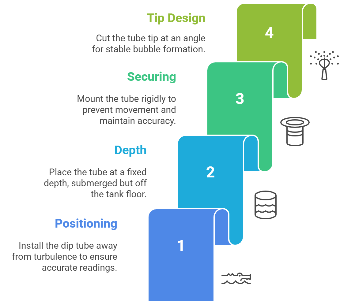
Positioning: The dip tube should be installed in a location that is representative of the true liquid level, away from areas of high turbulence such as pump inlets or direct filling streams, which could cause pressure fluctuations.
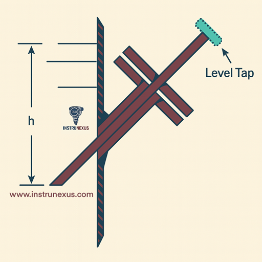
Depth: The outlet of the dip tube must be positioned at a fixed, known depth. It must be low enough to remain submerged even at the minimum anticipated liquid level to avoid loss of measurement. However, it should not be placed directly on the tank floor. A minimum clearance of 3 inches (75 mm) from the bottom is recommended to prevent clogging from sludge, sediment, or debris. A common and effective placement is to have the tube submerged 4 to 6 inches (100 to 150 mm) into the liquid at its lowest point.
Securing: It is imperative that the dip tube be rigidly mounted and secured. Any movement, swaying, or vibration of the tube will alter its vertical position relative to the liquid surface, causing erratic and inaccurate pressure readings.
Tip Design: As previously noted, the bottom of the tube should be cut with a V-notch or at a steep angle. This small but important detail promotes the formation of a steady stream of small bubbles, which is essential for a stable back pressure signal, rather than the intermittent release of large bubbles that can introduce noise into the measurement.
Pneumatic and Electrical System Integration and Leak Testing
Once the components are mounted, they must be interconnected. Pneumatic tubing should be routed from the control panel to the dip tube using paths that are as short and direct as possible. Long tubing runs and numerous bends should be avoided to minimize the potential for frictional pressure drop, which can introduce a positive offset error in the measurement.
Leak Testing: Before placing the system into service, the entire pneumatic circuit must be proven to be leak-free. This is a non-negotiable step for accurate operation. A common method is to temporarily seal the outlet of the dip tube, pressurize the system, and then shut off the supply. The pressure should hold steady; any drop indicates a leak. Alternatively, with the system pressurized, a soap-water solution can be applied to every fitting and connection; the formation of bubbles will pinpoint the location of any leaks. All identified leaks must be eliminated.
The electrical connection involves wiring the transmitter’s 4-20 mA output signal to the corresponding analog input on the PLC or controller, following the manufacturer’s wiring diagram.
Initial Calibration: Zero and Span Configuration
Calibration is the process of electronically configuring the transmitter to correlate the measured pressure range with the desired level range, setting the 4 mA output to the Lower Range Value (LRV) and the 20 mA output to the Upper Range Value (URV). This procedure validates the integrity of the entire system, from the dip tube tip to the controller’s display.
Zero Adjustment (4 mA / LRV): The zero point is calibrated when the liquid level is at its minimum defined point, which is most often with the tank empty. In this state, the hydrostatic pressure is zero. The transmitter’s zero adjustment or trim should be configured until the output signal is precisely 4.0 mA. If the output reads higher than 4.0 mA with an empty tank, it indicates the presence of a “zero shift,” likely caused by frictional pressure drop in the tubing. While this offset can be calibrated out electronically by adjusting the zero, it is indicative of a potential installation issue. The best practice is to address the physical cause (e.g., by using shorter or larger-diameter tubing) rather than simply compensating for it electronically.
Span Adjustment (20 mA / URV): The span is calibrated with the liquid at its maximum defined level (URV). The pressure at this point can be calculated using the formula: Pressure=Height × Specific Gravity × Constant. With the tank filled to this level, the transmitter’s span adjustment is trimmed until the output signal is precisely 20.0 mA. Some advanced systems facilitate a two-point field calibration, where the technician manually measures the level at two distinct points (one low, one high), enters these values into the controller, and the system automatically calculates the linear relationship between pressure and level.
Commissioning and System Verification
With the system installed and calibrated, the final step is to commission it for service. The purge gas supply is turned on, and the flow rate is carefully adjusted using the needle valve on the rotameter to achieve a slow, steady stream of bubbles—a rate of approximately 1.5 Standard Cubic Feet per Hour (SCFH) is a common starting point.
As a final verification, the level reading displayed on the controller should be checked against a direct manual measurement (e.g., using a dipstick or sight glass) at several intermediate points between the LRV and URV. This confirms the system’s linearity and accuracy across its entire operational range, providing confidence in its performance before it is handed over to operations.
Maintenance Protocols and Advanced Troubleshooting
The reliability of a bubble type level transmitter system is not inherent in its design alone; it is achieved through a disciplined program of preventive maintenance and a logical approach to troubleshooting. Because the system is an open-loop design that actively interfaces with both the process and the ambient environment, it is subject to wear and contamination. A proactive maintenance strategy is therefore not merely a best practice but an essential operational requirement for ensuring long-term accuracy and uptime.
Routine Preventive Maintenance Schedule
A structured maintenance schedule addresses the most common failure points before they can impact system performance.
- Weekly: A visual inspection should be performed. Check the air supply filters and any low-point drains for accumulated condensation and drain as necessary. Maintaining a clean, dry air supply is the single most critical factor for system health.
- Monthly: Observe the flow meter or rotameter to confirm that a consistent, stable air flow is being maintained. A drifting flow rate may indicate a developing issue with the regulator or a partial clog. Visually inspect the accessible portions of the dip tube for any signs of significant buildup or physical damage.
- Quarterly to Semi-Annually: Perform a comprehensive leak check of the entire pneumatic system using a soap solution, paying close attention to fittings and connections. If the system uses a desiccant dryer, inspect the indicator media. If the color has changed (e.g., from blue to pink), the desiccant is saturated and must be replaced or regenerated.
- Annually: A more thorough service is recommended. The dip tube should be removed from the vessel for a complete inspection and cleaning to remove any accumulated scale, sludge, or biological growth. Depending on the manufacturer’s recommendations, internal pneumatic components like reversing relays or restriction orifices should also be inspected and cleaned. Finally, perform a calibration verification by checking the system’s output at the zero and span points to ensure there has been no significant drift.
Diagnosing Common Faults: A Troubleshooting Guide
When problems arise, a systematic, “pneumatics-first” approach is most effective. The vast majority of bubbler system failures are rooted in the physical (pneumatic or mechanical) components rather than the electronics. The following table provides a guide to diagnosing and resolving common issues.
Problem | Potential Causes | Troubleshooting Steps & Solutions |
No Reading / No Output | Loss of power; Loss of air supply; Severely clogged dip tube; Transmitter failure. | 1. Verify electrical power to the transmitter and control panel. 2. Confirm the air compressor or plant air supply is active and the isolation valves are open. 3. Attempt a high-pressure purge. If unsuccessful, the tube must be removed and manually cleaned. 4. As a final step, check transmitter terminals for voltage and test for a current output. |
Fluctuating / Unstable Reading | Loose or vibrating dip tube; Intermittent large bubbles (“belching”); High process turbulence; Loose signal wiring; Electrical interference. | 1. Physically inspect the dip tube mounting to ensure it is rigidly secured. 2. Check that the dip tube tip has a proper V-notch and is not damaged, which can cause inconsistent bubble release. 3. Slowly adjust the air flow rate to find a point that stabilizes bubble formation. 4. Check and tighten all electrical connections at the transmitter and controller. 5. Investigate nearby sources of electrical noise (e.g., VFDs) and consider installing signal isolators if necessary. |
Reading is Falsely High | Excessive air flow rate causing frictional pressure drop; Partial clog in the dip tube creating a restriction. | 1. Observe the rotameter and reduce the air flow via the needle valve to the minimum rate required for steady bubbling (e.g., 1-3 bubbles/sec). 2. Initiate an automated purge cycle or manually clean the dip tube to remove any partial obstructions that would increase back pressure. |
Reading is Falsely Low or Zero | Leak in the air line/fittings; Insufficient air supply pressure; Water/condensate in the impulse line. | 1. Perform a thorough leak check on all pneumatic tubing and fittings with a soap solution and repair any identified leaks. 2. Verify the supply pressure regulator is set high enough to overcome the maximum possible liquid head. 3. Drain all filters, air tanks, and any low points in the tubing where liquid could accumulate. |
“Valve Hunting” (Oscillating Control) | System response is too fast for the process; Improper dip tube depth; Clogged internal reversing relay. | 1. Increase the dampening or filtering parameter in the controller or transmitter to slow the response to pressure changes. 2. Confirm the dip tube is submerged to the correct depth (typically 4-6 inches) at low level. 3. Disassemble and clean the internal components of the reversing relay or restriction screw as per manufacturer instructions. |
Winterization and Operation in Freezing Conditions
Operation in sub-zero temperatures presents a significant challenge for bubbler systems. The primary risk is the freezing of any moisture present within the pneumatic components, which can cause complete blockages and potentially damage regulators or valves.
Preventive Measures: The most critical countermeasure is ensuring the purge gas is exceptionally dry. This is achieved through high-efficiency desiccant dryers or refrigerated air dryers upstream of the bubbler panel. All external components, including the control panel and any exposed regulators, should be housed within heated and insulated enclosures. In extremely cold climates, it may be necessary to apply electrical heat tracing to exposed pneumatic lines to prevent any residual moisture from freezing. All condensate drain points must also be protected from freezing to ensure they remain functional.
Concluding Analysis and Selection Criteria
The bubble type level transmitter, one of the earliest and most enduring methods of continuous level measurement, occupies a unique and valuable position in the modern industrial instrumentation landscape. While it has been supplanted by non-contact technologies like radar and ultrasonic in many general-purpose applications, its fundamental design principles provide a robust and often superior solution for a specific class of challenging process environments. Its legacy is not one of obsolescence, but of evolution into a specialized tool for solving problems that remain difficult for other technologies.
Synthesizing the Role of Bubbler Systems in Modern Process Control
The bubbler system’s journey reflects the broader evolution of process control. Initially valued for its simplicity and effectiveness, it was a workhorse technology across many industries. With the advent of advanced, solid-state electronics, non-contact sensors offered the promise of lower maintenance and easier installation, leading to their widespread adoption. However, practical experience has revealed the limitations of these newer technologies in the face of real-world process complexities like foam, turbulence, corrosive media, and extreme temperatures.
In this context, the bubbler system has found its modern role. It is no longer the first choice for a simple water tank, but it is a leading contender for measuring the level in a wastewater lift station, a chemical processing tank with aggressive reagents, a thick slurry mixer, or a furnace of molten metal. Its core advantage—the complete isolation of the measurement electronics from the process fluid—remains a powerful differentiator. Modern advancements, including smart controllers with integrated diagnostics, automated purge and zeroing cycles, and versatile communication protocols, have further enhanced its reliability and reduced its maintenance burden, ensuring its continued relevance as an indispensable tool for the instrumentation engineer.
Decision Framework: When to Specify a Bubble Type Level Transmitter
The selection of a level measurement technology should be a process of elimination based on the most demanding aspects of the application. A bubble type level transmitter should be strongly considered, and is often the optimal choice, when the application meets one or more of the following “trigger conditions”:
![]() Challenging Process Fluid: Is the liquid highly corrosive, viscous, an abrasive slurry, or does it contain significant suspended solids or sludge? The bubbler’s physical separation and self-purging action make it exceptionally well-suited for these media.
Challenging Process Fluid: Is the liquid highly corrosive, viscous, an abrasive slurry, or does it contain significant suspended solids or sludge? The bubbler’s physical separation and self-purging action make it exceptionally well-suited for these media.
- Adverse Surface Conditions: Is the liquid surface prone to heavy or persistent foam, significant steam or vapor, or extreme turbulence from agitation? The bubbler’s submerged measurement point makes it immune to these conditions, which are known failure points for ultrasonic and some radar sensors.
- Extreme Process Temperature: Does the process temperature exceed the operational limits of other sensor technologies, such as temperatures above 350°F (177°C) or in applications involving molten materials? The bubbler’s ability to locate electronics remotely makes it a viable solution.
- Accessibility and Hazardous Location: Is the point of measurement located in a physically inaccessible area (e.g., deep well, sump) or a classified hazardous environment that prohibits the use of local electrical components? The bubbler’s remote sensing capability is a key advantage.
- History of Technology Failure: Have other technologies, particularly ultrasonic or submersible pressure transducers, been tried in this application and failed due to fouling, corrosion, or damage from debris? This is a strong indicator that the robust, isolated nature of a bubbler system is required.
If an application does not exhibit these challenging characteristics—for example, a clean liquid in a standard storage tank—other technologies like direct DP, ultrasonic, or radar may offer a more cost-effective and lower-maintenance solution. However, when faced with the industry’s most difficult level measurement problems, the bubble type level transmitter remains a proven, reliable, and often unparalleled solution.