
DP Level Transmitters in Oil and Gas: A Comprehensive Guide
In the fast-paced and high-stakes world of the oil and gas industry, precision is paramount. Inaccurate measurements can lead to significant financial losses, operational inefficiencies, and most importantly, serious safety hazards. Among the myriad of instruments crucial for seamless operations, the Differential Pressure (DP) level transmitter plays a pivotal role in monitoring and controlling fluid levels in various vessels and tanks. However, the reliability of these transmitters is only as good as their last calibration.
This in-depth guide provides a comprehensive overview of essential calibration tips for DP level transmitters, tailored specifically for the unique challenges of the oil and gas sector. From pre-calibration checks to mastering both dry and wet leg scenarios, this article will equip you with the knowledge to ensure your level measurements are consistently accurate and reliable.
The Critical Importance of Accurate DP Level Transmitter Calibration
Differential pressure level transmitters are the workhorses of level measurement in the oil and gas industry. They operate on the principle of measuring the pressure difference between two points—typically the bottom and top of a vessel—and converting this into a level reading. This simple yet effective method is used to measure liquid levels in a wide range of applications, from storage tanks to reactors and separators.

An inaccurate calibration can have a domino effect on your entire process. A faulty level reading might lead to:
Tank Overfills: This can result in costly product loss, environmental contamination, and significant safety risks, including the potential for fires and explosions.
Pump Damage: Incorrect low-level readings can cause pumps to run dry, leading to cavitation, overheating, and premature failure.
Process Inefficiency: Inaccurate level data can disrupt control loops, leading to suboptimal process conditions, reduced yield, and inconsistent product quality.
Inventory Discrepancies: Errors in level measurement can lead to incorrect inventory calculations, impacting financial reporting and regulatory compliance.
Regular and precise calibration is not just a matter of good practice; it’s a fundamental requirement for safe, efficient, and profitable operations in the oil and gas industry.
Pre-Calibration Checklist: Setting the Stage for Success
Before you even think about connecting a calibrator, a series of pre-calibration checks are essential to ensure a smooth and accurate process. Rushing this stage can lead to frustrating errors and rework.
Gather the Right Tools: Ensure you have all the necessary equipment on hand, including a certified pressure calibrator with sufficient accuracy, a HART communicator or other field communicator, hand tools for making adjustments, and any required personal protective equipment (PPE).
Review Documentation: Familiarize yourself with the transmitter’s manual, the process and instrumentation diagram (P&ID), and the specific calibration range for the application.
Isolate the Transmitter: Safely isolate the DP transmitter from the process by closing the block valves. Follow your site’s lockout/tagout (LOTO) procedures to the letter.
Inspect the Impulse Lines: Visually inspect the high-pressure (HP) and low-pressure (LP) impulse lines for any signs of leaks, blockages, or physical damage. For gas applications, ensure there’s no liquid accumulation, and for liquid applications, check for gas bubbles.
Equalize the Pressure: Open the equalizing valve on the three or five-valve manifold to apply the same pressure to both sides of the transmitter. This should result in a zero reading. If not, this indicates a potential issue that needs to be addressed before proceeding.
Vent to Atmosphere: For vented-to-atmosphere applications, ensure the low-pressure side is open to the atmosphere and not obstructed.
The Heart of the Matter: The Calibration Process
The specific calibration procedure for a DP level transmitter depends on whether it’s a “dry leg” or “wet leg” installation.
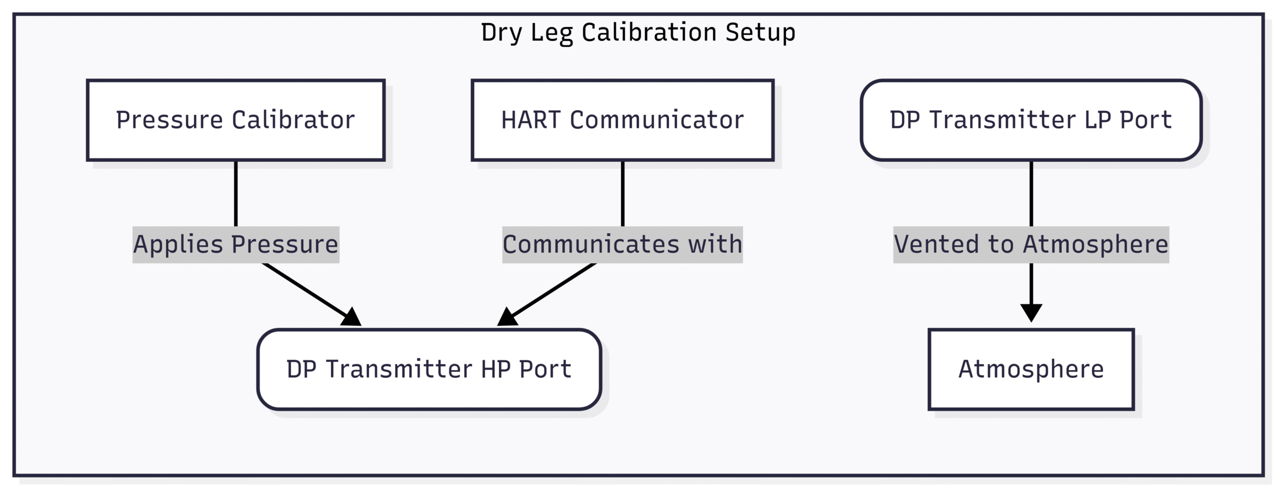
Dry Leg Calibration: The Simpler Scenario
A dry leg installation is used when the process vapor in the vessel is non-condensing and the low-pressure impulse line is filled with a gas (usually air or the process vapor itself). This is a common setup for many applications.
The goal of the calibration is to set the 4 mA (Lower Range Value or LRV) and 20 mA (Upper Range Value or URV) points corresponding to the minimum and maximum fluid levels in the tank.
Here’s a simplified breakdown of the process:
Zero Point Calibration (4 mA):
With the transmitter isolated and the equalizing valve open, the differential pressure is zero.
Connect the pressure calibrator to the high-pressure port of the transmitter. The low-pressure port remains open to the atmosphere.
Apply a pressure equal to the pressure exerted by the fluid at the minimum level (0% level). This is often zero if the transmitter is mounted at the same level as the minimum tank level.
Using the HART communicator, adjust the transmitter’s output to 4 mA.
Span Point Calibration (20 mA):
Calculate the pressure that will be exerted by the fluid at the maximum level (100% level). This is calculated as:
where:
is the pressure at maximum level
is the height of the fluid column between the minimum and maximum levels
is the specific gravity of the process fluid
Apply this calculated pressure to the high-pressure port of the transmitter using the pressure calibrator.
Adjust the transmitter’s output to 20 mA using the HART communicator.
Verification:
After setting the zero and span, it’s crucial to verify the transmitter’s linearity.
Apply pressures corresponding to 25%, 50%, and 75% of the calibrated range and check if the output in mA is as expected (8 mA, 12 mA, and 16 mA respectively).
Wet Leg Calibration: Handling Condensing Vapors
A wet leg installation is necessary when the process vapor in the vessel is likely to condense in the low-pressure impulse line. To prevent an erroneous and fluctuating pressure reading on the LP side, this line is intentionally filled with a reference fluid, creating a “wet leg.” The hydrostatic pressure of this wet leg must be compensated for during calibration.
The calibration process for a wet leg system is more complex as it involves accounting for the constant pressure from the wet leg.
Understanding the Pressures:
High-Pressure (HP) Side: The pressure on the HP side varies with the liquid level in the tank.
Low-Pressure (LP) Side: The pressure on the LP side is constant and is due to the hydrostatic head of the fluid in the wet leg.
Zero Point Calibration (4 mA – 0% Level):
At the minimum level (0%), the pressure on the HP side is due to any fluid head below the transmitter’s tapping point (if any).
The differential pressure at 0% is:
where:
is the differential pressure at the lower range value.
P_HP is the pressure on the high side at 0% level.
is the constant pressure from the wet leg.
Apply this calculated differential pressure (which will often be a negative value) to the transmitter and adjust the output to 4 mA.
Span Point Calibration (20 mA – 100% Level):
At the maximum level (100%), the pressure on the HP side is at its highest.
The differential pressure at 100% is:
where:
is the differential pressure at the upper range value.
P_HP(100%)is the pressure on the high side at 100% level.
is the constant pressure from the wet leg.
Apply this calculated differential pressure to the transmitter and adjust the output to 20 mA.
Verification:
As with the dry leg, verify the linearity at 25%, 50%, and 75% of the range.

Post-Calibration Best Practices: Ensuring Long-Term Reliability
The calibration process doesn’t end once you’ve set the 20 mA point. Following a few post-calibration steps is crucial for ensuring the long-term accuracy and reliability of your DP level transmitter.
Document Everything: Meticulously record all calibration data, including the as-found and as-left values, the date of calibration, the technician’s name, and any anomalies observed. This documentation is vital for trend analysis, troubleshooting, and regulatory audits.
Leak Check: Before returning the transmitter to service, perform a thorough leak check on all connections. Even a minor leak can significantly impact the accuracy of your measurements.
Return to Service Protocol: Follow your site’s specific procedures for returning the transmitter to service. This typically involves slowly opening the block valves to prevent a sudden pressure shock to the transmitter’s diaphragm.
Final Verification: Once the transmitter is back online, compare its reading with the actual process level (if possible through a sight glass or other means) to ensure it’s reading correctly under normal operating conditions.
Common Challenges and Troubleshooting
Even with the best procedures, you can encounter challenges during DP level transmitter calibration. Here are some common issues and their potential solutions:
Safety First: Calibration in Hazardous Environments
The oil and gas industry is synonymous with hazardous environments where flammable gases and vapors are often present. When calibrating DP level transmitters in these areas, safety is the absolute priority.
Intrinsically Safe Equipment: Always use intrinsically safe (IS) rated calibration equipment. IS devices are designed to limit the electrical and thermal energy to a level that cannot ignite a hazardous atmosphere.
Hot Work Permits: Obtain all necessary hot work permits before starting any calibration activity in a classified hazardous area.
Gas Detection: Use a portable gas detector to monitor the atmosphere for any flammable gases before and during the calibration process.
PPE is Non-Negotiable: Wear the appropriate Personal Protective Equipment (PPE), including flame-retardant clothing (FRC), safety glasses, and gloves.
Follow Site-Specific Safety Protocols: Every facility has its own set of safety procedures. Adhere to them strictly.
By prioritizing these safety measures, you can perform essential calibration tasks without compromising the well-being of your personnel or the integrity of your facility.
Conclusion: The Path to Precision and Safety
Calibrating DP level transmitters in the oil and gas industry is a meticulous but essential task. By understanding the fundamental principles, following a structured approach, and adhering to strict safety protocols, you can ensure that your level measurements are accurate, reliable, and contribute to the overall safety and efficiency of your operations. Regular and precise calibration is not just a maintenance task; it’s a commitment to excellence and a cornerstone of a robust process safety management program. By implementing the tips and techniques outlined in this guide, you can be confident that your DP level transmitters are performing at their best, providing the critical data needed to keep your processes running smoothly and safely.