📌 Introduction
Control valves are pivotal in process plants—they modulate flow, pressure, temperature, and level to meet process demands. A well-selected valve is only as effective as its installation. Even the highest-quality valve can underperform if installed incorrectly. Common installation pitfalls—such as piping misalignment, turbulence, poor orientation, and improper wiring—can severely degrade performance, accuracy, lifespan, and safety. Following precise installation guidelines ensures optimal valve control, fluid stability, minimal wear, and process dependability.
1. Pre-Installation Planning & Selection
1.1 Specifying the Right Valve
Choose a valve with appropriate size, pressure rating, material, end connections, and flow direction—these must align with process conditions
Valve sizing (Cv/Kv) ensures capacity meets flow demands without inducing cavitation or excessive drop .
Pressure ratings ensure safe operation during normal duty and pressure testing (e.g., 1.5× design).
Flow direction arrows on the valve body must match process flow
Materials must withstand fluid type, corrosion, temperature, and mechanical stress.
1.2 Instrumentation & Control Integration
Valve installation is part of a control loop comprising sensors, transmitters, controllers, actuators, and final elements. Confirm signal compatibility, pressure source (air/dry gas), and communication wiring to ensure responsiveness and stability
2. Piping Layout & Orientation
2.1 Flow Conditioning & Straight Runs
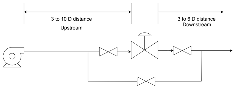
Install 3–10× pipe diameters upstream to minimize turbulence.
3–6× diameters downstream similarly required for stable flow
For compressible fluids (steam/gas) with major pressure drops, expand outlet piping to 2–3× valve inlet size
Well-conditioned flow prevents seat flutter, wear, control instability, and noise.
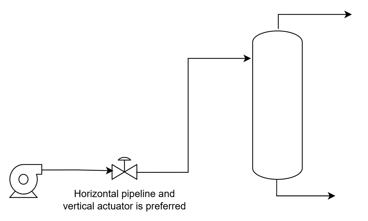
2.2 Horizontal vs Vertical Installation
Horizontal piping with vertical actuator is preferred: gravity aligns internals for even wear and proper lubrication
Vertical piping may be used but requires additional support and special orientation
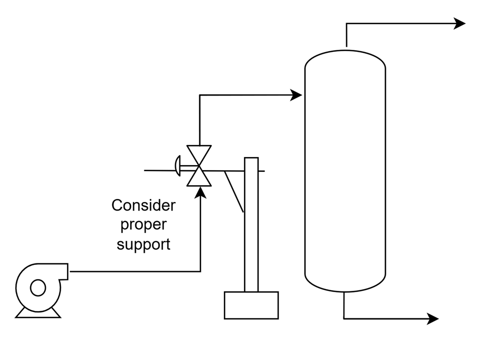
2.3 Support & Stress Relief
Piping must be independently supported. Never use the valve body as a structural anchor—misaligned flanges cause strain and damage
3. Isolation, Bypass & Protection
3.1 Isolation Valves
Install full-bore isolation valves (e.g., ball or gate valves) upstream and downstream for maintenance double block and bleed
3.2 Strainers & Steam Traps
Install strainers upstream to filter debris
In steam service, add steam separators, traps, and drains to remove condensate, prevent water hammer, and protect internals
3.3 Bypass Valve
Include a characterized bypass control valve to maintain system flow during valve service

4. Installation & Mechanical Setup
4.1 Valve Handling & Flange Connection
Always lift valves by the body or topworks—not tubing or smaller parts
Align flanges squarely, use new gaskets, and tighten bolts in a star pattern
For threaded connections, apply Teflon tape or sealant carefully—avoid excess that may enter the valve
4.2 Orientation Checks
Verify valve arrows align with flow. Ensure actuator spring-return setup matches the desired fail-safe (fail-open/fail-closed) position .
4.3 Clearance and Support
Maintain space above/below for maintenance/removal. Use sturdy brackets to support valve and actuator weight
5. Signal Lines & Pneumatic/Electrical Connections
5.1 Pneumatic Supply & Tubing
Use clean, dry, leak-free lines. Keep actuator tubing short and simple to minimize lag
5.2 Electrical Wiring
Follow manufacturer wiring instructions precisely.
Use proper rated voltage (24 V DC/AC), connectors, and avoid mis-wiring
Secure cables to prevent strain, interference, or moisture ingress .
6. Commissioning Procedures
6.1 Pressure Testing
Hydrotest to 1.5× design pressure—ensure valve internals withstand test conditions.
6.2 Functional Checks
With isolation valves closed, cycle actuator through full stroke manually or via controller. Confirm smooth operation without binding .
6.3 Positioner Calibration
Adjust the positioner to ensure valve travel matches signal. Validate stroke indicator with actual valve movement.
6.4 Leak Testing
Pressurize the system and inspect all joints for leaks. Re-tighten or replace gaskets as needed.
6.5 Flow Characterization
Test flow response across operating range. Check for chatter, hunting, noise, or cavitation. If necessary, adjust trim, pilot settings, or install dampeners .
7. Maintenance & Troubleshooting
7.1 Routine Maintenance
Visual checks: surfaces, insulation, corrosion.
Lubrication: stem, actuator per OEM.
Cycle isolation valves periodically to prevent seizing.
Replace seals/gaskets during planned shutdowns.
7.2 Packing Adjustment
Repack stem packing gradually, stroke valve to seat packing properly. Avoid over-tightening .
7.3 Tap & Maintenance Ports
Install pressure gauges upstream/downstream for diagnostics.
7.4 Navigating Common Issues
| Problem | Likely Cause | Recommended Action |
|---|---|---|
| Leakage | Gasket/piping issue | Retighten, replace gaskets |
| Hard operation | Debris or poor lubrication | Clean internals, lubricate |
| Noise/Chatter | Cavitation or turbulence | Improve piping, install dampeners |
| Valve doesn’t move | Signal, actuator, or supply | Check wiring, air pressure, positioner |
8. Advanced Installation Tips
8.1 Multi-Valve Configurations
Dual-valve setups offer redundancy and turndown flexibility—allowing staged control as demand changes .
8.2 Trim and Dampening
Select trims (e.g., cage trim) that reduce noise and wear. Use muffling orifice plates where needed
8.3 Standards & Regulations
Follow ISA, ASME, OSHA and regional standards. Document tests (hydro, fit, functional) for compliance .
9. Diagram Walkthrough
Referring to the diagram above:
Upstream piping runs straight for 3–10× diameter to ensure flow conditioning.
Isolation valve (Gate/Ball) before the strainer.
Strainer protects the valve from debris.
Control valve with flow arrow aligned horizontally, actuator atop.
Gauges before and after valve for diagnostics.
Bypass valve with isolation valves to facilitate maintenance.
Downstream straight run of 3–6× diameter, enlarged if needed (e.g., steam).
Drain/bleed valves and drain point for servicing and flushing.
10. Summary & Takeaways
Achieving the full potential of a control valve requires meticulous planning, execution, and ongoing care. Quick reference tasks:
Design & planning: align valve specs and piping layout.
Mechanical installation: precise alignment, proper support, and orientation.
Instrumentation: clean, leak-free connections.
Commissioning: thorough testing, calibration, and validation.
Maintenance: periodic inspection, lubrication, and troubleshooting.
Well-installed and maintained control valves lead to stable processes, long valve life, energy savings, safety, and lower operational costs.
Final Thought
A control valve isn’t just a mechanical component—it’s the control center of process regulation. By following installation best practices, maintaining the system, and respecting operational limits, you’re empowering valves to deliver precision control, reliability, and longevity. When in doubt, always fall back to OEM guidelines and consult instrumentation experts. A robust installation procedure today pays dividends in process performance and uptime tomorrow.