Connecting Sensors and Actuators: A Guide to DCS Input Modules
In the intricate world of industrial automation, the seamless flow of information is the lifeblood of any successful operation. At the heart of this data exchange lies the Distributed Control System (DCS), the brain that oversees and manages complex industrial processes. But how does this brain receive information from the outside world? How does it know the temperature of a reactor, the pressure in a pipeline, or the position of a valve? The answer lies in a critical, yet often overlooked, component: the DCS input module.
This comprehensive guide will demystify the world of DCS input modules. We’ll explore their fundamental role, dive deep into the different types, and provide practical advice on connecting sensors to ensure your control system receives accurate and reliable data. Whether you’re a seasoned control engineer, a maintenance technician, or a student of industrial automation, this guide will equip you with the knowledge to master the connection between the physical world and your digital control environment.
What is a Distributed Control System (DCS)?
Before we zoom in on input modules, let’s establish a clear understanding of the DCS itself. A Distributed Control System is a network of autonomous controllers distributed throughout a plant or industrial process. Unlike a centralized system where a single computer performs all control functions, a DCS divides the control tasks among multiple controllers, each responsible for a specific process area.
This distributed architecture offers significant advantages:
Enhanced Reliability: If one controller fails, the rest of the system can continue to operate, preventing a total plant shutdown.
Scalability: The system can be easily expanded by adding more controllers as the process grows.
Improved Performance: Local controllers can execute control loops faster and more efficiently.
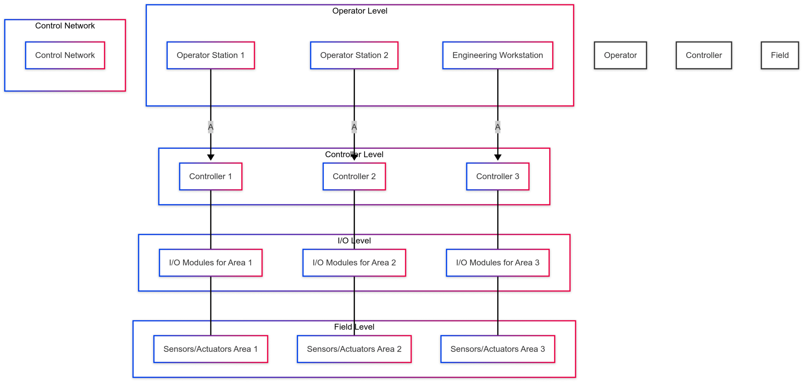
A typical DCS architecture includes a human-machine interface (HMI) for operator interaction, an engineering workstation for configuration, a communication network, and the process controllers themselves, which house the crucial input/output (I/O) modules.
The input modules are the system's senses, translating physical measurements from sensors into electrical signals the controller can understand. Conversely, output modules act as the system's hands, converting controller commands into actions performed by actuators like valves, motors, and pumps. This guide focuses on the "sensing" part of the equation: the input modules.
The Critical Role of Input Modules
Input modules, often called I/O cards or points, are the bridge between the field devices and the DCS controller’s processor. Their primary function is signal conditioning and conversion. A sensor in the field—measuring temperature, pressure, flow, or level—produces a raw electrical signal. This signal might be a variable voltage, a tiny current, or a simple on/off state.
The input module takes this raw signal and performs several key tasks:
Termination: Provides a physical point (screw terminals or connectors) to land the field wiring.
Isolation: Often provides electrical isolation (typically using opto-isolators or transformers) to protect the sensitive controller electronics from dangerous voltages and electrical noise from the field.
Filtering: Removes unwanted electrical noise from the incoming signal to ensure a stable and accurate reading.
Conversion: Converts the conditioned analog signal into a digital value (a process called Analog-to-Digital Conversion or ADC) that the controller’s processor can interpret.
Status Indication: Usually includes LEDs to provide a quick visual indication of the input’s status (e.g., power on, channel active, fault).
Without the correct input module properly configured and wired, the data fed into the DCS would be meaningless, leading to poor control, process upsets, and potential safety hazards.
Types of Input Signals and Modules
Industrial sensors communicate using a variety of signal types. Consequently, DCS vendors offer a range of input modules tailored to these specific signals. The two most fundamental categories are Analog and Digital.
Digital (Discrete) Inputs (DI)
Digital signals are the simplest form of communication. They represent a binary state: on or off, open or closed, true or false. Think of a light switch.
Common Applications: Push buttons, limit switches, motor run/stop status, pressure switches, level switches.
Signal Type: Typically a voltage level (e.g., 24 VDC, 120 VAC) or a dry contact (a simple switch that opens or closes a circuit provided by the input module).
Analog Inputs (AI)
Analog signals are continuous and can represent a range of values. Instead of just on/off, an analog signal can represent any value between its minimum and maximum limits.
Common Applications: Measuring process variables like temperature, pressure, flow rate, level, pH, or valve position.
Signal Type: The most common standard in modern industry is the 4-20 mA current loop. Other standards include 1-5 VDC, 0-10 VDC, and signals from specialized sensors like thermocouples and Resistance Temperature Detectors (RTDs).
Beyond these two primary types, there are also specialized modules for tasks like high-speed counting, vibration monitoring, and communication with intelligent field devices.
A Deep Dive into Analog Input (AI) Modules
Analog input modules are the workhorses of process control. They handle the nuanced data that allows for precise regulation of a process. Let’s break down the key characteristics and types.
The 4-20 mA Current Loop: The Industry Standard
The 4-20 milliamp (mA) current loop is the predominant method for transmitting analog sensor data in industrial environments. But why this specific range?
Live Zero: The “low” signal is 4 mA, not 0 mA. This is a crucial feature. A reading of 4 mA indicates the process is at 0% of its measured range (e.g., 0 psi), but the loop is still powered and functioning correctly. A reading of 0 mA indicates a fault, such as a broken wire or a failed sensor, allowing the system to immediately detect a problem.
Noise Immunity: Current signals are inherently less susceptible to electrical noise and interference over long cable runs compared to voltage signals. Voltage can drop over distance (a phenomenon known as voltage drop), but the current remains constant throughout the entire loop.
Power and Signal on Two Wires: The 4-20 mA signal can often power the sensor (transmitter) directly, simplifying wiring. These are known as “2-wire” or “loop-powered” transmitters.
An AI module designed for 4-20 mA inputs will typically have a precision resistor (often 250 Ω) across its input terminals. According to Ohm’s Law (), the 4-20 mA current flowing through this resistor creates a proportional 1-5 VDC voltage ( and ). The module’s internal circuitry then converts this voltage into a digital number.
Analog-to-Digital Converter (ADC) Resolution
The resolution of the ADC determines the precision of the measurement. It’s defined by the number of bits the ADC uses. A 12-bit ADC can represent discrete steps. A 16-bit ADC can represent steps. Higher resolution means the module can detect smaller changes in the input signal, resulting in a more accurate digital representation of the process variable.
For example, for a pressure transmitter calibrated from 0 to 1000 psi:
With a 12-bit ADC, the smallest detectable change in pressure would be .
With a 16-bit ADC, the smallest detectable change would be .
HART Protocol
Many modern 4-20 mA instruments are “smart” transmitters that use the HART (Highway Addressable Remote Transducer) Protocol. HART superimposes a low-level digital signal on top of the standard 4-20 mA analog signal. This allows for two-way communication without interfering with the primary process variable signal.
With a HART-enabled AI module, engineers can:
Remotely configure the transmitter (e.g., change its range).
Perform diagnostics and check device health.
Read additional process variables from a single device (e.g., a multivariable transmitter might send pressure via the 4-20 mA signal and temperature via the HART signal).
A Deep Dive into Digital Input (DI) Modules
While analog inputs provide the nuance, digital inputs provide the certainty. They are the system’s eyes and ears for definitive states.
Wet vs. Dry Contacts
DI modules are often designed to handle two types of inputs:
Dry Contact: This is a simple switch, relay contact, or transistor output that has no internal power source. The DI module itself provides the voltage (often called “wetting voltage”) and current to sense whether the contact is open or closed. When the external contact closes, it completes the circuit, and the module detects the current flow.
Wet Contact: This input comes from a field device that provides its own voltage signal to indicate its state (e.g., 24 VDC for “ON” and 0 VDC for “OFF”). The DI module simply needs to detect the presence or absence of this voltage.
It’s crucial to use the correct type of module for the application and to ensure it’s compatible with the voltage level of the field device (e.g., 24 VDC, 48 VDC, 120 VAC).
Special DI Features
Some DI modules offer advanced features:
Sequence of Events (SOE): These modules have high-resolution timestamps (often to the millisecond). They are used in applications like electrical switchgear to record the exact order in which circuit breakers or protective relays trip during a fault, which is invaluable for post-event analysis.
Pulse Counters: These modules are designed to count high-speed pulses from devices like turbine flow meters or encoders. They can calculate totals, rates, and frequencies directly on the module, offloading this task from the main controller.
Specialized Input Modules
Beyond standard AI and DI, many applications require specialized modules.
Thermocouple (TC) Input Modules
Thermocouples are popular temperature sensors that generate a tiny voltage (millivolts) that changes with temperature. They are inexpensive and can measure a very wide range of temperatures. However, they require a specialized input module because:
Low Signal Level: The signal is very small and requires high-gain amplification.
Non-Linearity: The relationship between voltage and temperature is not perfectly linear. The module must contain linearization curves for different thermocouple types (e.g., Type K, J, T, E).
Cold Junction Compensation (CJC): A thermocouple measures the temperature difference between its measurement tip and its connection terminals (the “cold junction”). To get an accurate reading, the module must measure the temperature at its own terminals (using a sensor like a thermistor) and add this value to the calculated temperature difference.
Resistance Temperature Detector (RTD) Input Modules
RTDs are another type of temperature sensor. They are more accurate and stable than thermocouples but have a smaller temperature range. An RTD works on the principle that the electrical resistance of a metal (typically platinum) changes predictably with temperature.
An RTD module measures this resistance. To do this accurately, it must compensate for the resistance of the lead wires connecting the RTD to the module. This is why RTDs often use 3-wire or 4-wire connections, and the input module must be designed to support this. A 4-wire measurement is the most accurate as it completely eliminates the lead wire resistance from the calculation.
Connecting Sensors to DCS Input Modules: A Practical Guide
Proper wiring is paramount. A poor connection can introduce noise, cause inaccurate readings, or create a safety risk.
Connecting a 2-Wire 4-20mA Transmitter
This is the most common connection in process control. The AI module provides the power for the loop.
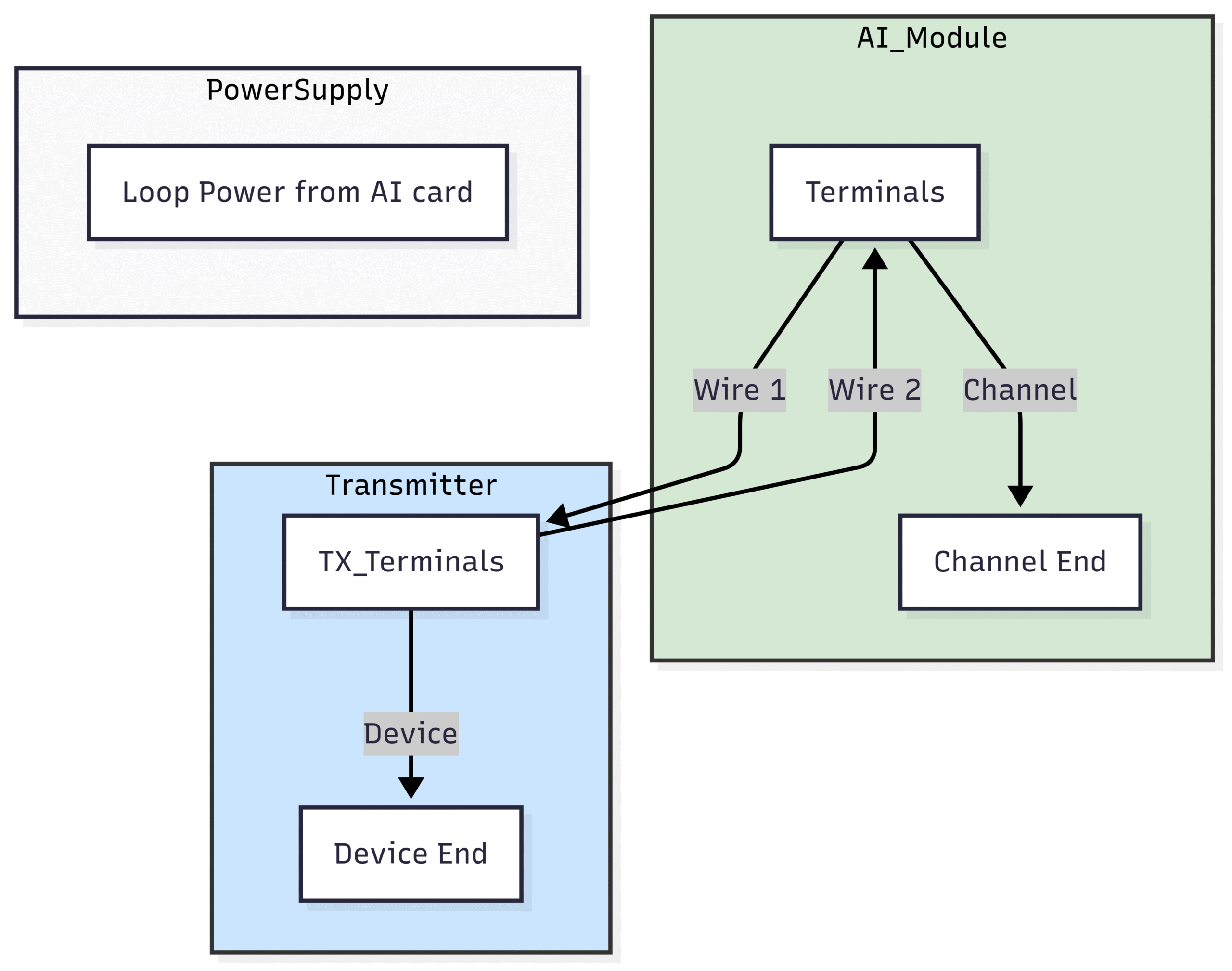
Wiring Steps:Connect the positive (+) terminal of the AI module channel to the positive (+) terminal of the transmitter.
Connect the negative (-) terminal of the transmitter to the negative (-) terminal of the same AI module channel.
Ensure the shield of the twisted-pair cable is grounded at one end only, typically at the DCS cabinet side, to prevent ground loops.
Connecting a Digital Limit Switch (Dry Contact)
Here, the DI module provides the wetting voltage to detect the switch position.

Wiring Steps:Connect the voltage source terminal (e.g., +24V) of the DI module channel to one side of the limit switch.
Connect the other side of the limit switch to the input terminal (e.g., IN) of the same DI module channel.
When the switch closes, the 24V signal is routed to the input terminal, and the module registers an “ON” state.
Connecting a Thermocouple
This requires a dedicated TC input module and specialized thermocouple extension wire.
Wiring Steps:Use the correct type of thermocouple extension wire that matches your thermocouple (e.g., Type K extension wire for a Type K thermocouple). Using standard copper wire will create an unwanted thermocouple junction at the connection point, leading to inaccurate readings.
Connect the positive (+) lead of the extension wire to the positive (+) terminal on the TC module.
Connect the negative (-) lead to the negative (-) terminal. Polarity is critical. Reversing the wires will cause the temperature to read in the wrong direction.
Land the shield at the DCS cabinet side only.
Best Practices for Installation and Wiring
To ensure signal integrity and system reliability, follow these best practices:
Use Shielded Twisted-Pair Cable: For all analog signals (4-20mA, TC, RTD), use shielded twisted-pair cable. The twisting helps cancel out electromagnetic interference (EMI), and the shield provides protection from electrostatic noise.
Proper Grounding: Ground the shield of analog signal cables at one end only, typically at the DCS panel. This prevents noise-inducing “ground loops.”
Segregate Wiring: Do not run low-level analog signal cables in the same tray or conduit as high-voltage power cables. The magnetic field from power cables can induce noise in the signal wires.
Follow Vendor Guidelines: Always refer to the DCS vendor’s documentation for specific wiring diagrams, terminal torque specifications, and module configuration requirements.
Label Everything: Clearly label every wire, terminal block, and module. This is invaluable for future troubleshooting and maintenance.
Verify Loop Integrity: Before commissioning, use a multimeter and a loop calibrator to verify the entire loop. For a 4-20 mA loop, you can inject 4mA and 20mA signals and confirm they are read correctly at the HMI.
Troubleshooting Common Input Issues
When a value on the HMI looks wrong, the input module and its wiring are often the first place to check.
Open Loop (Reading 0 mA): For a 4-20mA loop, a zero reading usually points to a broken wire, a loose terminal, a failed transmitter, or a blown fuse on the AI module.
Noisy or Fluctuating Reading: This is often caused by improper grounding, a damaged cable shield, or running signal cables too close to power cables. Check grounding and shielding first.
Incorrect Reading (But Stable): This could be a configuration issue. Check the scaling in the DCS (e.g., 4mA = 0 psi, 20mA = 1000 psi). It could also be a miscalibrated transmitter or the wrong type of module (e.g., using a voltage input module for a current signal).
DI Point Stuck On or Off: For a dry contact, this could be a failed switch or a short/open in the wiring. For a wet contact, check if the source device is providing the correct voltage. Also, check the status LED on the module itself.
Conclusion: The Foundation of Control
The world of industrial processes is built on data. The ability to accurately and reliably sense the state of the physical world is the absolute foundation of any advanced control strategy. DCS input modules are the unsung heroes of this process, diligently translating the language of sensors into the digital vocabulary of the controller.
By understanding the different types of signals, selecting the appropriate module for the task, and adhering to best practices for wiring and installation, you can ensure that your Distributed Control System has a clear and accurate view of the process it commands. From the simple certainty of a digital switch to the nuanced precision of a HART transmitter, mastering the connection to your input modules is a critical skill for any automation professional. It’s the first and most important step in transforming raw data into operational excellence.