
Introduction
Control valves play a critical role in regulating fluid flow, pressure, temperature, and level in process control industries such as oil & gas, chemical, power, and water treatment. One of the most crucial aspects of control valve performance is its flow characteristic—the relationship between valve travel (or stem position) and flow rate under constant pressure conditions.
Selecting the correct valve inherent or installed characteristic directly influences control loop performance, process stability, and overall system efficiency. This blog dives deep into control valve characteristics, explains the types, and offers guidance on how to select the right one for specific applications.
- What Are Control Valve Characteristics?
Control valve characteristics define how the flow capacity (Cv or % flow) changes with valve opening (% travel or stem position). It can be categorized into:
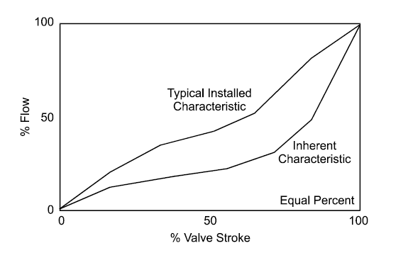
- Inherent Characteristics – Measured under constant pressure drop across the valve.
- Installed Characteristics – Reflects real-world behavior when pressure drop varies due to system dynamics.
Understanding both is vital for effective process control.
- Types of Control Valve Flow Characteristics
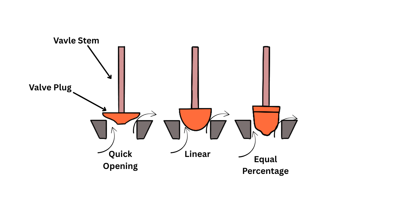
The three most common inherent flow characteristics are:
- Linear
- Definition: Equal increments of valve travel produce equal increments in flow.
- Graph: Straight line.
- Application: Ideal where pressure drop remains constant or nearly constant.
- Equal Percentage (Eq%)
- Definition: Equal increments of valve travel result in percentage-based increases in flow.
- Behavior: Small changes at low travel result in small flow changes; at high travel, large flow changes occur.
- Graph: Exponential curve.
- Application: Ideal when pressure drop across the valve varies significantly.
- Quick Opening
- Definition: Large increase in flow with small valve movement; then levels off.
- Graph: Sharp rise, then plateau.
- Application: Used for on-off services or applications where rapid opening is needed like relief or safety systems.

- Inherent vs Installed Characteristics
| Feature | Inherent Characteristic | Installed Characteristic |
| Conditions | Constant pressure drop | Real process dynamics |
| Use | Valve sizing & selection | System performance tuning |
| Output | Manufacturer curves | Field-measured curves |
Installed characteristic is influenced by piping resistance, pump head curve, and other system pressure losses. Even a valve with an equal percentage inherent characteristic might behave linearly when installed, depending on system dynamics.
- Valve Characteristic Selection: Key Factors
Choosing the right valve characteristic depends on several factors:
- Process Dynamics
- Varying pressure drop? Use equal percentage.
- Constant pressure drop? Linear is more suitable.
- Control Range
- Equal percentage valves offer better control over wide flow ranges.
- Linear valves perform best when process remains in mid-travel range.
- Type of Control Loop
- Flow control loops: Equal percentage for wide flow changes.
- Level control: Linear or equal percentage depending on tank dynamics.
- Pressure control: Equal percentage usually works better.
- Installed Pressure Drop (ΔP)
- If ΔP across the valve changes significantly with flow, equal percentage is better.
- If ΔP is nearly constant (e.g., with pressure control valves in high-pressure systems), linear can be ideal.
- Turndown Ratio
Equal percentage valves provide higher turndown ratios and more precise low-flow control.
- Typical Application-wise Selection Guide
Here’s a tabular summary to guide selection:
| Application | Recommended Characteristic | Reason |
| Flow Control (general) | Equal Percentage | Better control at varying flows |
| Level Control (small tanks) | Linear | Simplified, predictable response |
| Level Control (large tanks) | Equal Percentage | Small changes needed at low level |
| Pressure Control | Equal Percentage | Maintains stability across pressure ranges |
| Temperature Control | Equal Percentage | Works well with heat exchanger nonlinearities |
| Mixing Applications | Linear | Balanced input/output ratios |
| On-Off or Fast Action | Quick Opening | Rapid actuation required |
| Steam Control | Equal Percentage | Non-linear steam flow characteristics |
| Pump Recirculation | Linear or Equal Percentage | Based on piping resistance and system curve |
- Graphical Comparison
Imagine 100% flow:
- At 50% travel:
- Linear valve gives ~50% flow.
- Equal percentage gives ~20-30% flow.
- Quick opening gives ~80% flow.
This shows why equal percentage valves give finer control in low-flow regions.
- Matching Valve with Control Loop Gain
Loop gain is the product of process gain, valve gain, and controller gain. A valve’s flow characteristic directly affects loop gain.
- Equal percentage valves help maintain constant loop gain in systems where the process gain increases with flow.
- Linear valves suit processes with constant process gain.
- Valve Sizing and Rangeability Considerations
- Rangeability
Defined as the ratio of maximum controllable flow to minimum controllable flow.
- Linear: ~50:1
- Equal percentage: ~100:1
- Quick opening: ~20:1
If your process needs fine control at low flows, equal percentage wins.
- Valve Sizing
Oversized valves cause:
- Poor controllability
- Instability
- Excessive wear
Always size valves to operate in the 20–80% travel range for optimal control.
- Examples of Field Applications
Example 1: Heat Exchanger Bypass Control
- Requirement: Stable temperature control, varying flow.
- Characteristic: Equal Percentage
- Justification: Handles wide range of flow and nonlinear heat transfer.
Example 2: Condenser Level Control
- Requirement: Precise control around a narrow level band.
- Characteristic: Linear
- Justification: Provides stable response in nearly linear systems.
Example 3: Fuel Gas Pressure Control
- Requirement: Constant outlet pressure, varying inlet pressure.
- Characteristic: Equal Percentage
- Justification: Maintains loop gain in a compressible fluid system.
- Limitations of Each Characteristic
| Characteristic | Limitations |
| Linear | Not suitable for systems with large flow range |
| Equal Percentage | Poor low-flow control if not sized properly |
| Quick Opening | Not good for throttling or modulating control |
- Control Valve Positioner and Characteristics
Advanced digital positioners can modify valve characteristics digitally. For example:
- Linearizing an equal percentage valve.
- Customizing the installed characteristic curve.
This adds flexibility during commissioning and optimization.
- Control Valve and Actuator Considerations
When selecting valve characteristics, also consider:
- Actuator stroke and resolution
- Speed of response
Mismatch between valve characteristic and actuator performance can reduce controllability.
Control System Tuning Impacts
Poorly chosen valve characteristics can:
- Cause loop oscillations
- Increase integral windup
- Lead to valve hunting or excessive wear
Loop tuning becomes easier when the valve responds predictably and consistently across its operating range.
- Best Practices in Valve Characteristic Selection
- Use equal percentage as default unless application dictates otherwise.
- Consult process simulation data for accurate modeling.
- Consider installed characteristic using system curves during design.
- Don’t oversize the valve—this affects control and rangeability.
- Use characterization cages or custom trims when needed for non-standard applications.
Conclusion
Selecting the right control valve characteristic is a foundational step in designing effective and responsive process control systems. By understanding the difference between inherent and installed characteristics, and aligning valve behavior with process dynamics, engineers can ensure optimal control, stability, and energy efficiency.
In summary:
- Use equal percentage for most pressure- and temperature-sensitive systems.
- Choose linear for simple flow or level systems.
- Go with quick opening for on-off or relief applications.
Combining a well-characterized valve with proper sizing, actuator selection, and control strategy will elevate your system’s performance and reliability.