Control Valve Installation Best Practices for Engineers: Ensuring Optimal Performance and Longevity
Control valves are the workhorses of any process control system. They are the final control elements that directly manipulate the flow of fluids, playing a critical role in maintaining process parameters within desired limits. A properly selected control valve can only deliver its intended performance if it is installed correctly. Incorrect installation can lead to problems, including reduced accuracy, premature failure, safety hazards, and costly downtime.
This comprehensive guide is designed for instrumentation engineers and technicians in India, providing in-depth knowledge and best practices for the successful installation of control valves. By adhering to these guidelines, you can ensure optimal performance, extend the lifespan of your valves, and contribute to a safer and more efficient plant operation.
Why Proper Control Valve Installation Matters
In the dynamic landscape of process industries in India, where efficiency and safety are paramount, the importance of correct control valve installation cannot be overstated. Several factors underscore this significance:
- Performance Optimization: A correctly installed valve operates smoothly and accurately, ensuring precise control of process variables like flow, pressure, temperature, and level. This leads to improved product quality and reduced process variability.
- Reduced Maintenance Costs: Proper installation minimizes stress on valve components, reducing wear and tear and extending the Mean Time Between Failures (MTBF). This translates to lower maintenance costs and less frequent replacements.
- Enhanced Safety: Incorrectly installed valves can pose significant safety risks, including leaks, ruptures, and uncontrolled process deviations. Following best practices mitigates these risks, creating a safer working environment.
- Minimized Downtime: Failures due to improper installation can lead to unplanned shutdowns, resulting in significant production losses. Correct installation helps prevent these issues, maximizing plant uptime.
- Accurate Calibration and Tuning: A well-installed valve provides a stable and predictable response, making it easier to calibrate and tune the control loop for optimal performance.
Pre-Installation Checks: Laying the Foundation for Success
Before even thinking about bolting the control valve into the pipeline, a thorough pre-installation check is crucial. This stage involves verifying various aspects to ensure that the valve is suitable for the intended service and that all necessary components are in order.
1. Valve Identification and Specifications Verification:
- Compare Nameplate Data: Carefully compare the information on the valve nameplate with the project specifications, Piping and Instrumentation Diagram (P&ID), and the valve datasheet. Ensure that the valve type, size, material, pressure rating, temperature rating, and end connections match the requirements.
- Actuator and Accessories: Verify that the actuator type (e.g., pneumatic, electric), size, and operating range are correct. Check the specifications of any accessories, such as positioners, limit switches, solenoids, and pressure regulators.
2. Internal Inspection:
- Remove Packaging: Carefully remove all packaging materials and protective covers.
- Check for Damage: Visually inspect the valve body, actuator, and accessories for any signs of damage that may have occurred during shipping or handling. Look for dents, scratches, bent parts, or loose connections.
- Inspect the Valve Internals: If possible and without voiding any warranties, inspect the valve trim (seat, plug, stem) for any damage or foreign material. Ensure that the valve moves freely and is not stuck in any position.
- Cleanliness: Ensure that the valve body and internals are clean and free from any debris, welding spatter, or other foreign materials that could interfere with its operation.
3. Pipeline and Installation Environment Assessment:
- Pipeline Compatibility: Verify that the pipeline material, size, and schedule are compatible with the control valve. Ensure that the pipe flanges or threaded connections match those of the valve.
- Pipe Cleanliness: Ensure that the pipeline is thoroughly flushed and cleaned to remove any scale, debris, or welding residue that could damage the valve or impede flow.
- Accessibility: Check for adequate space around the installation location for operation, maintenance, and removal of the valve and its actuator. Ensure sufficient clearance for tools and personnel.
- Environmental Conditions: Consider the ambient temperature, humidity, and potential exposure to corrosive substances. Select appropriate valve materials and accessories to withstand the operating environment.
- Support Structure: Ensure that the pipeline is adequately supported and that there is no undue stress or strain on the valve due to misalignment or lack of support.
Block Diagram 1: Pre-Installation Checks Workflow

Installation Procedures: Step-by-Step Guide
Once the pre-installation checks are complete, the actual installation process can begin. Following these steps carefully will ensure a successful and trouble-free installation.
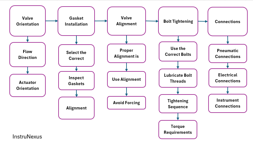
1. Valve Orientation:
- Flow Direction: Ensure that the valve is installed with the correct flow direction, as indicated by the arrow on the valve body. Installing the valve backward can lead to incorrect operation and potential damage.
- Actuator Orientation: Orient the actuator in a position that allows for easy access for maintenance, calibration, and connection of pneumatic or electrical lines. Consider factors like headroom and accessibility for tools. Generally, mounting the actuator vertically upwards is preferred to prevent accumulation of dust and moisture.
2. Gasket Installation:
- Select the Correct Gasket: Choose a gasket material and type that is compatible with the process fluid, temperature, and pressure. Ensure that the gasket size matches the flange rating and size.
- Inspect Gaskets: Check the gaskets for any damage or imperfections before installation.
- Alignment: Carefully align the gasket between the flanges, ensuring that it is centered and does not protrude into the flow path.
3. Valve Alignment:
- Proper Alignment is Crucial: Ensure that the valve flanges are perfectly aligned with the pipeline flanges. Misalignment can cause stress on the valve body, leading to leaks and premature failure.
- Use Alignment Pins: Use alignment pins to help align the flanges before inserting the bolts.
- Avoid Forcing: Never force the valve into place by tightening the bolts unevenly. If the flanges do not align easily, re-evaluate the piping and make necessary adjustments.
4. Bolt Tightening:
- Use the Correct Bolts: Use bolts of the correct material, size, and grade for the flange rating. Ensure that the bolt length is appropriate for the flange thickness and the number of washers being used.
- Lubricate Bolt Threads: Lubricating the bolt threads can help ensure proper and even tightening.
- Tightening Sequence: Tighten the bolts in a star or cross pattern, gradually and in multiple passes. This ensures even distribution of pressure on the gasket.
- Torque Requirements: Tighten the bolts to the specified torque values using a calibrated torque wrench. Refer to the valve manufacturer’s recommendations or relevant industry standards for the correct torque values.
5. Connections:
- Pneumatic Connections: Connect the air supply lines to the actuator and any pneumatic accessories (e.g., positioner, solenoid valve). Use clean, dry, and regulated air supply as per the manufacturer’s specifications. Ensure that all fittings are tight and leak-free.
- Electrical Connections: Connect the electrical wiring for the actuator, positioner, limit switches, and other electrical accessories according to the wiring diagrams and relevant electrical codes. Ensure proper grounding and use appropriate cable glands and conduits.
- Instrument Connections: Connect any signal lines (e.g., 4-20 mA control signal, feedback signals) to the appropriate terminals. Ensure correct polarity and secure connections.
Block Diagram 2: Control Valve Installation Steps
Post-Installation Procedures: Ensuring Readiness for Operation
After the mechanical and electrical connections are complete, several post-installation checks and procedures are necessary to ensure that the control valve is ready for operation.
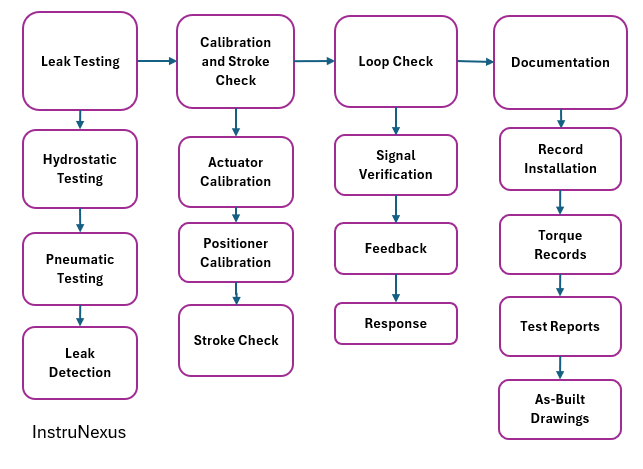
1. Leak Testing:
- Hydrostatic Testing: Perform hydrostatic testing of the installed valve and piping system according to relevant standards and procedures. Gradually increase the pressure to the specified test pressure and check for any leaks at the flanges, body connections, and packing.
- Pneumatic Testing: If hydrostatic testing is not feasible or required, perform pneumatic testing at a lower pressure. Exercise extreme caution during pneumatic testing due to the compressibility of gases.
- Leak Detection: Use appropriate leak detection methods (e.g., soap solution, electronic leak detectors) to identify any leaks. Rectify any leaks before proceeding further.
2. Calibration and Stroke Check:
- Actuator Calibration: Calibrate the actuator according to the manufacturer’s instructions to ensure that it responds correctly to the input signal.
- Positioner Calibration: If a positioner is used, calibrate it to ensure accurate positioning of the valve stem in response to the control signal.
- Stroke Check: Verify the full travel of the valve stem from fully closed to fully open position. Ensure that there are no obstructions and that the valve moves smoothly throughout its stroke.
3. Loop Check:
- Signal Verification: Verify the integrity of the control signal from the control system to the valve actuator.
- Feedback Verification: Check the feedback signal from the positioner (if used) back to the control system.
- Response Testing: Conduct basic response tests to ensure that the valve responds correctly and predictably to changes in the control signal.
4. Documentation:
- Record Installation Details: Document the date of installation, valve tag number, installer’s name, and any relevant observations or issues encountered during installation.
- Torque Records: Record the torque values applied to the flange bolts.
- Test Reports: Maintain records of all pre-installation checks, leak tests, calibration reports, and loop check results.
- As-Built Drawings: Update the P&IDs and other relevant drawings to reflect the actual installation.
Table 1: Control Valve Installation Checklist
Common Pitfalls to Avoid
Several common mistakes can occur during control valve installation. Being aware of these pitfalls can help engineers avoid costly errors and ensure a successful installation:
- Ignoring Pre-Installation Checks: Failing to thoroughly inspect the valve and pipeline before installation can lead to the installation of damaged or unsuitable components.
- Incorrect Valve Selection: Using a valve that is not properly sized or specified for the application will result in poor control performance and potential failures.
- Improper Handling: Rough handling of the valve during transportation and installation can cause damage to internal components.
- Misalignment: Forcing misaligned flanges together can damage the valve body and lead to leaks.
- Over- or Under-Tightening Bolts: Incorrect bolt torque can result in leaks or damage to the flange and gasket.
- Using Incorrect Gaskets: Selecting a gasket material that is not compatible with the process fluid or temperature can lead to premature failure and leaks.
- Neglecting Pipeline Cleanliness: Debris in the pipeline can damage the valve trim and impede its operation.
- Incorrect Wiring and Pneumatic Connections: Improper connections can lead to malfunction of the actuator and accessories.
- Insufficient Support: Lack of proper pipeline support can put undue stress on the valve.
- Inadequate Accessibility: Failing to provide sufficient space around the valve can hinder maintenance and troubleshooting efforts.
- Lack of Documentation: Poor documentation can make it difficult to track installation details, identify problems, and perform future maintenance.
Conclusion
Proper control valve installation is a critical aspect of ensuring the reliable and efficient operation of process plants. By adhering to the best practices outlined in this guide, instrumentation engineers in India can significantly improve the performance, longevity, and safety of their control valve installations. Meticulous pre-installation checks, careful execution of installation procedures, thorough post-installation testing, and comprehensive documentation are all essential steps in achieving this goal. Remember that investing time and effort in proper installation practices will pay off in the long run through reduced maintenance costs, minimized downtime, and a safer, more productive plant environment. By focusing on these key areas, instrumentation professionals can continue to contribute to the growth and success of the process industries in India.
SEO Keywords: Control Valve Installation, Best Practices, Instrumentation Engineers, India, Process Control, Valve Alignment, Bolt Tightening, Leak Testing, Calibration, Pre-Installation Checks, Maintenance, Safety, Block Diagrams, Tables.